1
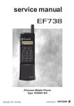
Chapter 2
APPLICATION PACKAGE MOTION
Control connections for
point-to-point positioning
X5
1
+ 10 V
2
- 10 V
Supply voltage analog output
max. 20 m
3
ISA0-
4
ISA0+
Neg. HW limit switch
5
ISA1
6
GND_ISA1
7
+ 24 V
8
+ 24 V
9
IS00
10
IS01
11
ENPO
Release power stage
12
OS00
Ready
13
OS01
Standstill
14
DGND
Digital ground
15
24V_EXT
16
GND_EXT
17
GND_EXT
Feed release
3
NC
Manual/automatic
Pos. HW limit switch
1
1
2
1
2
,
18
OS03
19
OS02/3
20
OS02/4
24 V
10 %, 35 AA
24
V ±+10%,
GND
,
,
Relay output of holding brake
+24V
1
M
3~
X13
13
25
4
22
9
4
+24V
21
8
20
7
GND
19
6
18
5
17
4
16
3
15
2
14
1
À
Á
Â
OE03
OE02
OE01
OE00
24V-OUT
GND-OUT
+24V
3
DGND
n.c.
GND-IN
IE07
IE06
IE05
IE04
IE03
IE02
IE01
IE00
Output: No tracking error
Output: reference point defined
Output: axis in position
Output: axis in position 0 (reference point)
24 V supply for outputs OE00 ... 03
Ground for outputs OE00 ... 03
Ground for inputs IE00 ... 07
Input p3
Input p2
Input p1
Input p0
Input: jogInput: jog+
Input: start release
Input: reference cam
Earth all screens at both ends to the casing over a large surface area using cable clamps!
Only use the control voltage connection for version SN2 (external supply of the control unit)!
The internal 24 V of the servocontroller is used to supply inputs and outputs at X5
(max. loading capacity: 200 mA in total).
Issue: January 1999
2-17