1
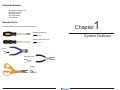
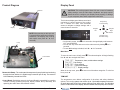
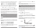
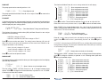
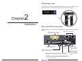
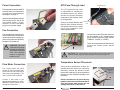
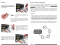
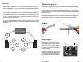
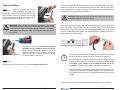
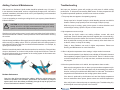
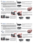
®
Superior Liquid Cooling Systems
www.koolance.com
RP-1250
User’s Manual
English v1.01
ISO
9001
Printed in Korea
This User Manual is updated regularly. Please be sure to check our support page for a newer
version of this guide: www.koolance.com/support
GENERAL PRECAUTION
Please read this manual carefully before beginning the installation of your Koolance system.
This manual assumes the user has basic experience in building and configuring computer
systems. Information referring to traditional hardware assembly is intentionally brief.
ABOUT SIGNS
Throughout this document, critical information is highlighted in gray-colored boxes. The
following symbols are intended to help prevent any situation which may cause personal
injury and/or damage to equipment:
!
!
WARNING: Indicates a potentially hazardous situation which, if not avoided,
could result in personal injury or be life-threatening.
CAUTION: Indicates a potentially hazardous situation which, if not avoided,
may result in damage to equipment or property.
PROHIBITED: Indicates a prohibited action.
PROHIBITED USE
This product is designed, developed and manufactured as contemplated for general use,
including without limitation: general office use, personal use and household use, but is not
designed, developed and manufactured as contemplated for use accompanying fatal risks or
dangers that, unless extremely high safety is secured, could lead directly to death, personal
injury, severe physical damage or other loss, including without limitation: nuclear power core
control, airplane control, air traffic control, mass transport operation control, life support,
or weapon launching control. If these products are used in such hazardous environments,
Koolance Incorporated does not warrant them.
TRADEMARKS
The Koolance name and logo are trademarks or registered trademarks of Koolance, Inc.
Other company and product names used in this publication are for identification purposes
only and may be trademarks or registered trademarks of their respective companies.
COPYRIGHT
All rights reserved. Copyright (C) Koolance Incorporated.
User Manual
i
!
WARNING: The Koolance liquid & coolant pack contain chemicals
which may be harmful or fatal if swallowed. KEEP THIS AND ALL
DANGEROUS CHEMICALS OUT OF THE REACH OF CHILDREN. If
ingestion has occurred, seek medical attention immediately. Give two
glasses of water. Do not induce vomiting. In the case of eye contact,
flush eyes immediately with water for 15 minutes. Remove contact
lenses. Call a physician if irritation persists. Some individuals may
have an allergic skin reaction with the solution, although generally mild.
Avoid contact as much as possible, and wash exposed area with soap
and water for at least 15 minutes. If irritation persists, or if contact has
been prolonged, get medical help. For further information, please visit
our website at: www.koolance.com
Table of Contents
System Features
1
Product Diagram ............................................................................................. 2
Display Panel .................................................................................................. 3
Installation
10
Positioning the Unit ....................................................................................... 11
Reservoir & Pump Connections .................................................................... 11
Power Connection ......................................................................................... 12
Fan Connection ............................................................................................. 12
!
CAUTION: Installation of third-party cooling products is done at the
user’s own risk. Koolance Inc. assumes no responsibility for damage
or loss due to the installation or use of this product. Additionally, adding
liquid coolers and other components to computer hardware may void
the hardware manufacturer’s original warranty. If you have any specific
questions on warranty coverage, please contact your component or
computer manufacturer. If there is any point of installation that you do
not understand, please contact our Technical Support Staff at: tech@
koolance.com, or visit our website at: www.koolance.com/support
Flow Meter Connection ................................................................................. 12
ATX Pass-Through Lead ............................................................................... 13
Temperature Sensor Placement ................................................................... 13
Fittings .......................................................................................................... 14
Cooler & Tubing Configuration ...................................................................... 15
Disconnecting Hoses .................................................................................... 17
Hose Lengths ................................................................................................ 17
KOOLANCE CONTACT INFORMATION
Koolance Incorporated (USA)
Filling & Maintenance
19
Testing & Filling ............................................................................................. 20
Adding Coolers & Maintenance .................................................................... 22
Address:
Telephone:
Fax:
Sales Email:
Tech Email:
ii
2840 W. Valley Hwy. N., Auburn, WA, USA 98001
+01-253-893-7551
+01-253-893-7573
[email protected]
[email protected]
Troubleshooting ............................................................................................ 23
Limited Warranty ........................................................................................... 26
User Manual
iii
Included Hardware
- Temperature Sensors (x3)
- ATX Pass-Thru Wire
- Mounting screws
- ATX Jumper Wire
- User Manual
Required Tools
During installation, you may need the following tools:
Chapter
flat-head screw driver
1
System Features
phillips-head screw driver
pliers
long-nose pliers
scissors
iv
User Manual
1
Product Diagram
Display Panel
Reservoir
!
CAUTION: This cooling system allows full user control of hardware
safety settings, such as audio alarm, shutdown, and pump speed.
Please be sure to configure your Display Panel properly, or damage
to your computer, data, and/or equipment could result.
The Koolance display panel allows control and
monitoring of various aspects of the cooling
unit. 4 buttons are used, with directional
arrows to navigate or change settings, and a
center button to enter/exit.
Display
Control Buttons
NOTE: After powering on this unit, wait
5 seconds before powering it off again.
Otherwise, the display may lock-up
and require reset (hold ▼ + ▲ for 5
seconds.)
Pump
Navigate Up,
Increase Setting
Navigate
Left
◙
Navigate
Right
Enter/Exit
Navigate Down,
Decrease Setting
◙
• On the main screen, hold
for 3 seconds to change display units between
ºC/ºF and LPM/GPM.
• You can exit any menu and return to the main screen by holding
for 2
seconds.
• To reset ALL settings to default, hold ▼ + ▲ for 5 seconds.
◙
Main Menu
Control Board
To enter the main menu, briefly press
Use ▼ and ▲ to navigate this menu.
◙. The selected option will begin flashing.
▲ TEMP SET: Temperature, alarm, and shutdown settings
FAN SET: Fan settings
PUMP SET: Pump settings
FLOW SET: Flow meter settings
▼ DISPLAY SET: Display settings
Reservoir & Pump - The coolant tank is transparent for easy liquid-level monitoring
through the front window. It is filled through a metal fill port on top. The reservoir
is illuminated by internal blue LEDs.
Control Board - Behind the reservoir, the Control Board is responsible for a number
of tasks, including: powering the pump, display, radiator fans (if attached), and
operating the audio alarm and shutdown modes.
2
System Features
When in the top menu, press
here, press ◄.
◙ to enter one of the above categories. To exit from
TEMP SET
The temperature menu allows configuration of the alarm and safety shutdown
options. This cooling system can monitor up to 3 (included) temperature sensors.
An audio alarm will sound if any sensor reaches its set alarm point. The offending
sensor will also flash in the display, and the radiator fans and pump will increase
User Manual
3
to 100% power. If any sensor reaches its set shutdown point, the system will
shutdown power to the computer via relay using the “ATX pass-through” wire.
▲ TEMP1
TEMP2
▼ TEMP3
55C
51C
60C
56C : Sensor #1, Alarm Point, Shutdown Point
54C : Sensor #2, Alarm Point, Shutdown Point
70C : Sensor #3, Alarm Point, Shutdown Point
When in the “Temperature Settings” menu, the selected temperature sensor will
to select a sensor to configure:
flash. Press ▼ and ▲ to navigate, or press
◙
TEMP1
AL: 55C
SET
PW: 56C : AL = Alarm, PW = Power (Shutdown)
◙
The alarm value will flash. Press ▼ or ▲ to adjust a value. Press
to change
to the shutdown temperature. Press
again to exit configuration of this sensor.
Press ◄ to return to the previous menu.
◙
NOTE: The shutdown temperature must be at least 1ºC (1-2ºF) higher than the
alarm temperature. If an alarm temperature can not be increased, increase the
shutdown temperature first. The minimum and maximum temperature range
allowable is 0-99ºC (32-210ºF).
CAUTION: Generally, sensors report liquid temperature at the water
block, which is typically 5-10°C (9-18°F) lower than the actual heat
source. This difference must be considered if adjusting alarm/shutdown
temperatures. Setting alarm/shutdown modes at too high of temperature can eliminate this feature’s effectiveness. The default Koolance
settings are designed to help compensate for differences in temp.
!
FAN SET
This unit has three fan channels which can be independently adjusted.
Alternatively, use the master fan channel (“ALL FANS”) to adjust all fan channels
simultaneously.
▲ ALL FANS
FAN1 SET
FAN2 SET
▼ FAN3 SET
50% :
84% :
47% :
30% :
All Fans (Master), Speed Setting %
Fan Channel #1, Speed Setting %
Fan Channel #2, Speed Setting %
Fan Channel #3, Speed Setting %
The selected fan channel will flash. Press ▼ and ▲ to navigate, press ◄ to return
to the previous menu, or press
to configure this fan channel:
◙
ALL FANS
4
50%
System Features
The speed value will flash. Press ▼ or ▲ to adjust this value. Press
the setting.
◙ to confirm
Higher fan speeds can improve performance, but will produce more noise. Fan
speeds can be adjusted manually from 0-100%.
!
CAUTION: Fan percentages are based on PWM duty. Fans will not
operate if set too low. Some types of fans may also not be compatible
with the PWM program and will only operate reliably at 100%.
Instead of manual speeds, fans can also be set to automatic. This is highly
recommended, since speeds will change based on temperature sensor feedback.
This is a good way to keep noise levels to a minimum while allowing the cooling
system to respond to temperature. To set a fan channel to automatic, press ▲ past
100% until “AUTO” is shown:
ALL FANS
From here, press
AUTO
◙ to configure the automatic mode:
ALL FANS
T1
L45C
AUTO
H80C : Temp Sensor, Low Point, High Point
The number following “T” designates the temperature sensor this fan channel will
follow. When flashing, press ▼ or ▲ to change sensors (1-3). Press
to move
to the next option.
◙
The number following “L” is the temperature low point. The number following “H”
is the temperature high point. Automatic fan control will adjust fans on a dynamic
ramp between these two points:
100%
Automatic
Fan Power
20%
42ºC
(Low Point)
60ºC
(High Point)
◙
When the temperature low point is flashing, press ▼ or ▲ to adjust it. Press
to
move to the temperature high point, and press ▼ or ▲ to adjust it. Press
again
to return to the previous menu.
◙
User Manual
5
The first line will flash. Press ▼ or ▲ to change what this line will display:
PUMP SET
▲
The pump speed can be manually set from 1-10:
PUMP(1-10)
7LV : Pump Speed Level
The pump speed level will flash. Press ▼ or ▲ to adjust. Press
previous menu.
◙ to return to the
FLOW SET
▼
If a Koolance flow meter (sold separately) has been connected to the slot interface
adapter, configuration is needed to properly display its values. Only one flow meter
can be displayed by the cooling system.
FLOW METER SET
FM-17
ID: 10mm : Flow Meter Model, Tubing Internal Diameter
◙
Press
to move to the next option. The tubing internal diameter (ID) size will
flash. This refers to the hose size attached to the flow meter itself. Press ▼ or ▲
to adjust this based on the following:
• 6mm (1/4 inch): change to “ID: 6mm”
• 10mm (3/8 inch): change to “ID: 10mm”
• 13mm (1/2 inch): change to “ID: 13mm”
Press
◙
When “FIXED” is the chosen display option, line 1 and 2 can be changed quickly
without reentering the DISPLAY SET menu. To do this, briefly press ▲ from the
main screen. The first line will flash:
Press ▼ or ▲ to change what this line will display among the options described
earlier. Press
to move to line 2, and similarly use ▼ or ▲. Press
again to
exit.
◙
▲
CYCLIC : Show 2 values or cycle multiple values
The first option, “FIXED”, will flash. Press ◄ or ► to change between these
options. Press
to configure one of the selections, or press ▲ to exit. If “FIXED”
is selected, two lines will be shown:
◙
TEMP1
TEMP1
◙
If “CYCLIC” is chosen from the DISPLAY SET menu, multiple values will be rotated
through the front display. The first option is whether these values will cycle vertically
or horizontally through the display:
◙
The display settings configure which values you wish to appear on the front display
and how they are shown:
6
TEMP1
21.7C : First line display option
PUMP
5400RPM : Second line display option
HORI: Rotate values vertically or horizontally
The first option, “VERT”, will flash. Press ◄ or ► to change between these options,
press
to configure a selection, or press ▲ to exit. Choosing either option with
will list all available values:
DISPLAY SET
DISPLAY
FIXED
◙
CYCLIC
VERT
◙ to return to the previous menu.
21.7C : Show temperature sensor #1
21.2C : Show temperature sensor #2
20.8C : Show temperature sensor #3
1770RPM : Show fan channel #1
1640RPM : Show fan channel #2
1820RPM : Show fan channel #3
5730RPM : Show pump speed
4.1LPM: Show flow rate
to confirm. The second line will flash. Press ▼ or ▲ to adjust this line.
Press
Press ◄ to return to the previous menu, or press
to return to the main screen.
The Koolance flow meter model number (SKU) will flash. Press ▼ or ▲ to adjust
this based on the following:
• INS-FM16: change to “FM-16”
• INS-FM17, INS-FM17N, INS-FM18: change to “FM-17”
TEMP1
TEMP2
TEMP3
FAN1
FAN2
FAN3
PUMP
FLOW
▼
◙
*TEMP1
*TEMP2
*TEMP3
*FAN1
*FAN2
*FAN3
*PUMP
*FLOW
21.7C : Show temperature sensor #1
21.2C : Show temperature sensor #2
20.8C : Show temperature sensor #3
1770RPM : Show fan channel #1
1640RPM : Show fan channel #2
1820RPM : Show fan channel #3
5730RPM : Show pump speed
4.1LPM: Show flow rate
21.7C : First line display option
21.7C : Second line display option
System Features
User Manual
7
◙
to
The selected line will flash. Use ▼ and ▲ to navigate to other lines. Press
enable or disable each value. This will remove the asterisk, thereby hiding that line
from being shown on the main screen:
▲ *TEMP1
*TEMP2
*TEMP3
*FAN1
*FAN2
*FAN3
*PUMP
▼ *FLOW
21.7C : (shown)
21.2C : (shown)
20.8C : (not shown)
1770RPM : (shown)
1640RPM : (not shown)
1820RPM : (not shown)
5730RPM : (shown)
4.1LPM: (shown)
Press ◄ to return to the previous menu, or press ► to exit DISPLAY SET.
This page is intentionally left blank.
8
System Features
User Manual
9
Positioning the Unit
The cooling unit is designed to operate in one orientation. In other directions, the
pump and reservoir may not bleed properly and could lead to cavitation.
Chapter
2
YES
NO
Installation
Reservoir & Pump Connections
The rear of the unit accepts various connections to integrate with your cooling
system.
FAN: Radiator fan connections
(2.0A max per plug, 4.5A total)
POWER: Connection from
power supply, 12VDC
IN/OUT: Liquid fitting sockets
PUMP:
Internal
pump
TEMP: Temperature sensors
shown on the front display
ATX: Wire lead for safety shutdown relay. For computer use,
leave the 2-pin wire connected to “NO” (Normally Open) pins.
ON/SYNC/OFF:
Adjusts LED lighting
of INS-FM16 flow
meter
INS-FM17/INS-FM16:
Connect an optional
flow meter to display
flow rate
If this unit’s relay feature (see: “Alarm and Shutdown Settings”,
pg.4) will be used for an application requiring a Normally Closed
circuit, move wire lead to “NC”.
10
Installation
User Manual
11
Power Connection
ATX Pass-Through Lead
The temperature sensors and ATX
lead may come pre-connected to
your unit. If not, connect them per
the diagram on page 11.
The ATX pass-through lead
is responsible for sending the
shut-down signal if any sensor
reaches the preset shutdown
temperature (See Display Panel
for configuration).
Attach the included power harness
to the location on the rear of the
unit marked “Power”. To this,
connect a 12 Volt 4-pin Molex
plug from your power supply.
There is no polarity direction with
the ATX lead. Connect the male
ATX power lead from the cooling
unit to your computer’s main
chassis power button.
Fan Connection
This unit has three connections to
power radiator fans. Multiple fans
can be combined into a single plug.
(A fan wiring harness is optionally
available from Koolance).
!
To Motherboard
From Cooling
Unit
Connect the female ATX power lead from
the Slot Adapter to the motherboard’s
power switch connection (often marked
“PWRSW”, “PWSW”, or “PWBT”).
This is the connection that would normally
receive the chassis power button
directly.
CAUTION : The total
combined amperage
of all fans connected to
the unit can not exceed
4.5A. The maximum
load on a single fan
header is 2.0A.
!
CAUTION: The auto shutdown safety feature of this product will not
function without properly connecting the ATX pass-through lead.
Temperature Sensor Placement
Flow Meter Connection
The cooling system can show
values for one Koolance INSFM16, INS-FM17/N, or INS-FM18
flow meter (sold separately). The
use of a flow meter is optional.
Three surface temperature sensors are
included with this product for monitoring.
Generally, sensors are affixed to water
blocks with metal tape. (Liquid temperature
sensors are also available optionally from
Koolance.)
Connect a flow meter to the
appropriately labeled plug. (Note:
INS-FM18 should connect to the
plug labeled “INS-FM17”.)
Sensors should never be placed directly
between a heat source and its water block.
This will interfere with contact and can
damage the sensor or heat source.
12
Chassis Power
Button
Installation
User Manual
Chip contact
area
(keep out)
13
Fittings
Cooler & Tubing Configuration
There are a vast number of methods for configuring a liquid cooling system
(serial, parallel, combinations, alternating components, etc.). There is no single
“correct” way! As long as coolant is flowing and you are satisfied with your device
temperatures, it’s an acceptable configuration.
Install the G 1/4 BSP threaded fittings you
purchased for your unit. It’s recommended
to hand-tighten all fittings to avoid
damaging the unit.
Similarly, the maximum number of water blocks allowed in a system will depend
upon your own configuration and thermal requirements. It’s common to see five or
more coolers in a Koolance system, but the limit is at what temperature you are
comfortable with.
Serial Loops
Cut tubing into two segments. You
will need to connect each to the rear
fittings.
Each hose connection will use a threaded compression
ring or hose clamp to keep it secure. Be sure to thread
the compression ring or hose clamp onto the hose
before attaching it.
A basic serial loop is recommended for *almost* every situation. Provided your
cooling system has a radiator of sufficient size for your total heat load, expect only
a minor difference between outlet and inlet temperatures. In computer cooling,
a delta of less than 1 to 3ºC (1.8 to 5.4ºF) is typical for the heat exchanger. This
means for most loops, you don’t need to worry about “hot water” moving from
one block to the next. It gets only a little warmer throughout the entire loop.
Generally, series is the simplest and most effective configuration. Each device is
daisy-chained to the next, usually starting with the most temperature-critical:
Squeeze the tube while pushing it
firmly over the fitting. Tubing should
completely cover the fitting.
Wetting the end of the hose with warm
water can make installation much
easier.
Chipset
Block
Video
Block
Cooling System
(Radiator, Pump, Reservoir)
Tighten the connection by sliding the
compression fitting down over the fitting
and screwing securely. For hose barbs,
use pliers to move it into the proper
position.
14
CPU
Block
Installation
User Manual
Video
Block
15
Parallel Loops
Disconnecting Hoses
Parallel loops are normally used to help accommodate water blocks with
significantly disproportionate flow restriction. They can become quite complicated
and if not well-planned, may lower performance through added bottlenecks and
pressure drop.
One suggestion for parallel loops is to reduce tubing size when splitting. Ideally,
the hose area going into the splitter will be roughly equal to (or slightly lower than)
the combined hose area coming out. For example, 3/8” (10mm) tubing split into
two 3/8” (10mm) paths would lose more pressure than splitting from 3/8” (10mm)
into two or three 1/4” (6mm) paths.
Nozzles are designed to attach tightly. If you need to remove a hose for any reason,
it may not pull off easily, even after unscrewing the compression fitting.
Usually, a connection will come free by squeezing the hose on top of the fitting and
twisting/pulling away. If this fails, cutting a small incision lengthwise (parallel) along
the fitting will free it.
When a hose has been removed, it may be distorted. This last portion (about 1cm,
7/16”) should be trimmed to ensure a perfect fit with the next connection. The tip
should always be re-cut if you needed to remove the tubing with an incision.
If you are considering a parallel flow path, we would encourage you to experiment
with different setups. There may be more optimal configurations than the example
shown below.
Cooling System
mm
10
10
mm
(Radiator, Pump, Reservoir)
mm
HD
Block
Chipset
Block
Splitter
6
6mm
Chipset
Block
RAM
Block
6mm
RAM
Block
Hose Lengths
6mm
6mm
Splitter
10m
m
CPU
Block
6mm
HD
Block
Before installing your liquid coolers,
appropriate lengths of tubing must be cut
to connect each device. For computer
cooling, it’s generally easier to estimate
the required amounts with hardware
already mounted.
Coolant
Inlet
Coolant
Outlet
On the rear of the unit, the inlet and outlet
locations will be labeled. Generally, the
outlet will connect first with your CPU
Cooler or the most temperature-sensitive
device.
16
Installation
User Manual
17
Liquid Coolers
You should now install the liquid coolers (CPU, GPU, Hard
Drive, etc.) to your hardware before continuing this User Manual.
Please refer to your cooler kit’s individual installation instructions,
then continue on to the next section.
With the connected outlet
hose, roughly estimate the
length you will need to your
first cooler, and cut it.
Cut the second hose with
enough length to reach the
last water block that will be in
your system.
Chapter
Using the leftover tubing, cut
shorter pieces to link between
each individual cooler.
3
Filling & Maintenance
NOTE: When filling the reservoir later, it will need to be pulled out from the front
chassis drive bay by about 2.75” (7cm). Be sure to leave enough tubing between
the reservoir unit and connected components to do this.
!
WARNING: The cooling system’s pump can not be run dry for any
period of time. Never power-on the computer or cooling system without
sufficient liquid in the reservoir. Dry-running (and thereby damaging
the pump) is not covered under the Koolance product warranty.
Continue connecting all of
your coolers in the system
until there are no longer
any open tube ends.
18
Installation
User Manual
19
The cooling system should be powered on to assist in the filling process. This also
allows you to check hose connections and make sure there are no tubing folds,
leaks, or blockages. If cooling a computer, this can be done without powering on
other hardware for extra safety (see below).
Testing & Filling
Once all the water blocks have
been connected, the system can
be filled with coolant. The fill port is located on top
of the reservoir. Free this component by removing
its side drive screws. Slowly pull it out just enough
to expose the refill plug (about 2.75”, 7cm).
!
!
WARNING: Most coolants are electrically conductive. Use caution
when filling the system, and keep all liquids away from electronics and
power cables. In case of emergency during installation, immediately
unplug the primary AC power cable. Dry the system thoroughly before
proceeding.
Slowly fill the system. To maintain the product
warranty, use only Koolance approved coolant.
Many alternative liquids and additives can cause
permanent damage to the cooling unit (through
chemical reaction, corrosion, biological growth,
thermal expansion, viscosity, etc.).
Replace the fill port on the reservoir. Do not overtighten the fill port.
CAUTION: Jumping the incorrect ATX power supply pins can cause
permanent damage to the power supply.
Make sure the AC power cord is attached to the power supply. If the power supply
has a rear switch, it must be set to the ON (-) position. Using the included green
Jumper Wire, insert the metal prongs into the fourth and sixth holes on the 20-24
pin ATX motherboard power supply plug as labeled below (usually green and a
black ground wire; See diagram).
If your pump has a speed control option, set it to the lowest level during
this time. Allow the pump to run until the liquid noise subsides.
During this process, cooling systems often need to be tilted gently
to allow air to escape from the pump and radiator. Until the pump
is “burped” in this manner, it can cavitate and there will be no
circulation. (This does NOT indicate a problem with the pump.)
The reservoir level will decrease during this procedure. Remove the
fill port cap and add more liquid when needed. If you frequently hear
this rushing noise in the future, it usually indicates the need for more
coolant.
That’s it! Replace the ATX motherboard connection and boot-up the computer.
20
Filling & Maintenance
User Manual
21
Adding Coolers & Maintenance
Troubleshooting
With normal use, Koolance’s liquid coolant should be replaced every 2-3 years. If
it ever becomes contaminated, unclear, or significantly changes color, it should be
replaced immediately. A Koolance “drain valve” (sold separately) is recommended
to make that process easier.
We hope your Koolance system will provide you with years of reliable cooling
performance. To help avoid unnecessary RMA issues, we have prepared this list
of possible operational problems, and their most common solutions.
If you are upgrading or removing a cooling block in your system, please follow the
instructions below.
!
CAUTION: Any time a hose is disconnected with coolant still inside,
leaking will occur. It is highly recommended to empty your cooling
system of coolant before disconnecting any hoses.
1. The pump does not appear to be operating properly...
Pumps need to be “burped” during the initial bleeding process to avoid this
situation. Reduce pump speed (but not low enough to stop the pump).
While the pump is running, gently tilt the system in various directions until
coolant begins moving. Open the fill port to relieve excess air.
2. My temperatures seem too high...
Working on a liquid cooling system is much easier and safer when liquid coolant is
removed beforehand. However, certain procedures can be done without removing
the coolant.
A binder clamp (available at office supply stores) is helpful for keeping a hose folded
while removing or adding coolers. Even so, pressure within the cooling system is
such that liquid will not easily flow out unless relieved elsewhere-- for example, by
opening the reservoir fill port.
Bend the hose directly before and after the section to be worked on. Place a binder
clamp on both bends, or tie them in this position to help avoid fluid loss. There will
be some liquid exposed; do not operate on the cooling system in this manner near
or above electronic hardware.
Verify that the liquid coolers are making sufficient contact with each
component. Ensure thermal paste has been applied (but not excessively),
that the block’s protective bottom film has been removed, and that the water
block is positioned correctly (see the cooler’s manual). Also check there are
no blocks, twists, or crimps in the tubing.
Finally, a dusty Radiator can result in higher temperatures. Please see
Draining and Maintenance for more information.
3. When I adjust the temperature alarm settings, it skips number increments...
This is normal operation if your display is set to display in Fahrenheit, because
the temperature program is based on units Celsius. Some ºC values convert
to decimal temperatures in ºF, or skip over them, and these can not be set by
the program.
4. After the system has been on for awhile, the temperature alarm sounds...
Make sure the temperature is at or above your preset alarm temperature (default is 50ºC, 122ºF). If not, the audio alarm may be emanating from another
location, such as your motherboard’s BIOS alarm or video card. The Koolance
temperature will flash whenever the cooling system alarm sounds.
Radiator Performance
Over time, dust will accumulate on the radiator. While the cooling system may
continue to operate in this condition, performance can decrease. To keep the
system clean, check the radiator periodically (through the top fan grill) and use
a can of electronics air cleaner if necessary.
22
Filling & Maintenance
If the alarm is produced by the Koolance unit and the display temperature
has not reached the alarm preset, please contact our technical department.
Also verify that the fans and pump are operating (see Troubleshooting #1),
and that liquid movement is present in the reservoir.
User Manual
23
5. My system has boot-up problems, or does not turn on...
Make sure the ATX wire lead is connected to “NO” (Normally Open) on the rear
of the unit. (See: “Reservoir and Pump Connections” for details.)
If this does not solve the issue, it is unrelated to the Koolance unit. In a computer,
a problem with the RAM, motherboard, power supply, video card, processor,
or monitor can cause the system to appear not to boot-up properly.
10. The flow meter reads “0”.
Make sure the Koolance flow meter you have purchased is directly connected
to the back of the unit (See Connecting the Unit). Also be sure the correct flow
meter model and tubing ID are selected via the front display (See Display
Panel).
6. My system appears to be leaking fluid...
It is possible a connection was not properly sealed (however unlikely). If you
can see liquid somewhere on the tubing, or at the bottom of the chassis,
computer components may need to be removed for a system test (see Testing
& Filling).
If liquid should get onto another computer component, shut down the system,
and remove the component. In many cases, the hardware will be fine after
allowing it to dry. However, the system should not be operated until you have
discovered where the leak is coming from and can repair the problem. Should
the leak be situated somewhere where it can not be easily repaired, please
contact our Technical Department for further assistance.
7. My computer’s BIOS gives me errors that there is no cooling fan attached...
Some motherboards will not boot, or may generate an error or alarm if no
cooling fan is attached to the CPU or motherboard chipset power connectors.
There is typically an option to disable this warning in BIOS, but you may
need to boot with a fan attached initially to disable this setting. If the system
is not booting due to this problem, clear the CMOS and try configuring BIOS
again.
8. The Display Panel shows “OPEN” for a temperature sensor...
This indicates a temperature sensor was not found for the specified channel.
If there is no sensor connected to that channel, this is its normal status.
9. The front display is locked up or not responding.
This can happen if the unit is powered off within 5 seconds of being powered
on. Reset the display to manufacturer defaults by holding ▼ + ▲ for 5 seconds.
Three beeps will be heard to indicate the unit was reset. After a reset, all configuration settings (temperature, alarm, fans, etc.) must be updated again.
24
User Manual
25
Limited Warranty
Koolance Incorporated (“Koolance”) warrants each new Koolance liquid-cooled
system (“the system”), against defects in materials or workmanship for a period of
one year from the date of purchase, and agrees to repair or replace any defective
Koolance system without charge. Shipping costs are non-refundable.
This warranty is non-transferable. All warranty claims must be accompanied by the original
proof of purchase.
THIS WARRANTY DOES NOT COVER DAMAGE RESULTING FROM ACCIDENT,
MISUSE OR ABUSE, LACK OF REASONABLE CARE, SHIPPING DAMAGE,
MODIFICATIONS, THE AFFIXING OF ANY ATTACHMENT NOT PROVIDED WITH
THE PRODUCT, LOSS OF PARTS, OR OPERATING COMPONENTS AT SPEEDS OR
FUNCTIONS OTHER THAN THOSE SPECIFIED BY THEIR MANUFACTURERS.
Use of unauthorized replacement parts or liquids will void this warranty. Koolance
Incorporated will not pay for warranty service performed by a non-authorized repair
or diagnostic service and will not reimburse the consumer for damage resulting from
warranty service performed by a non-authorized repair service. No responsibility is
assumed for any special incidental or consequential damages due to a defective Koolance
product.
In order to obtain warranty service, contact our RMA department for information. The
product must be shipped postage prepaid to an authorized Koolance service location. It
is suggested that, for your protection, you return shipments of product by insured mail,
insurance prepaid. Damage occurring during shipment is not covered by this warranty.
Shipping costs are non-refundable. No other warranty, written or oral, is authorized by
Koolance Incorporated.
Disclaimer
IN NO EVENT SHALL KOOLANCE INCORPORATED OR ITS EMPLOYEES, AGENTS,
SUPPLIERS, MANUFACTURERS, OR CONTRACTORS BE LIABLE FOR ANY
DAMAGES OF ANY KIND OR CHARACTER, INCLUDING WITHOUT LIMITATION
ANY COMPENSATORY, INCIDENTAL, DIRECT, INDIRECT, SPECIAL, PUNITIVE, OR
CONSEQUENTIAL DAMAGES, LOSS OF USE, LOSS OF DATA, LOSS OF INCOME OR
PROFIT, LOSS OF OR DAMAGE TO PERSONS OR PROPERTY, CLAIMS OF THIRD
PARTIES, OR OTHER LOSSES OF ANY KIND OR CHARACTER, AND WHETHER
OR NOT THE POSSIBILITY OF SUCH LOSS OR DAMAGE HAS BEEN NOTIFIED TO
KOOLANCE INCORPORATED.
26