1
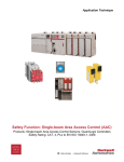
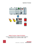
Application Technique
Safety Function: Single-beam Area Access Control (AAC)
Products: Guardmaster Dual-input Safety Relay, Single-beam Area Access
Control Sensors with E-stop
Safety Rating: CAT. 4, PLe to EN ISO 13849-1: 2008
2
Safety Function: Single-beam Area Access Control (AAC)
Important User Information
Read this document and the documents listed in the additional resources section about installation,
configuration, and operation of this equipment before you install, configure, operate, or maintain this
product. Users are required to familiarize themselves with installation and wiring instructions in addition
to requirements of all applicable codes, laws, and standards.
Activities including installation, adjustments, putting into service, use, assembly, disassembly, and
maintenance are required to be carried out by suitably trained personnel in accordance with applicable
code of practice.
If this equipment is used in a manner not specified by the manufacturer, the protection provided by the
equipment may be impaired.
In no event will Rockwell Automation, Inc. be responsible or liable for indirect or consequential
damages resulting from the use or application of this equipment.
The examples and diagrams in this manual are included solely for illustrative purposes. Because of the
many variables and requirements associated with any particular installation, Rockwell Automation, Inc.
cannot assume responsibility or liability for actual use based on the examples and diagrams.
No patent liability is assumed by Rockwell Automation, Inc. with respect to use of information, circuits,
equipment, or software described in this manual.
Reproduction of the contents of this manual, in whole or in part, without written permission of Rockwell
Automation, Inc., is prohibited.
Throughout this manual, when necessary, we use notes to make you aware of safety considerations.
WARNING: Identifies information about practices or circumstances that can
cause an explosion in a hazardous environment, which may lead to personal
injury or death, property damage, or economic loss.
ATTENTION: Identifies information about practices or circumstances that can
lead to personal injury or death, property damage, or economic loss. Attentions
help you identify a hazard, avoid a hazard, and recognize the consequence.
IMPORTANT
Identifies information that is critical for successful application and
understanding of the product.
Labels may also be on or inside the equipment to provide specific precautions.
SHOCK HAZARD: Labels may be on or inside the equipment, for example, a
drive or motor, to alert people that dangerous voltage may be present.
BURN HAZARD: Labels may be on or inside the equipment, for example, a
drive or motor, to alert people that surfaces may reach dangerous
temperatures.
ARC FLASH HAZARD: Labels may be on or inside the equipment, for
example, a motor control center, to alert people to potential Arc Flash. Arc
Flash will cause severe injury or death. Wear proper Personal Protective
Equipment (PPE). Follow ALL Regulatory requirements for safe work practices
and for Personal Protective Equipment (PPE).
Rockwell Automation Publication SAFETY-AT110A-EN-P – November 2013
Safety Function: Single-beam Area Access Control (AAC)
3
General Safety Information
Contact Rockwell Automation to find out more about our safety risk assessment
services.
IMPORTANT
This application example is for advanced users and
assumes that you are trained and experienced in safety
system requirements.
ATTENTION: Perform a risk assessment to make sure all
task and hazard combinations have been identified and
addressed. The risk assessment can require additional
circuitry to reduce the risk to a tolerable level. Safety circuits
must take into consideration safety distance calculations,
which are not part of the scope of this document.
Table of Contents
Important User Information ....................................................................................... 2
General Safety Information ....................................................................................... 3
Introduction ............................................................................................................... 3
Safety Function Realization: Risk Assessment ......................................................... 4
Single-beam Area Access Control Sensor Safety Function ....................................... 4
Safety Function Requirements .................................................................................. 4
Functional Safety Description ................................................................................... 5
Bill of Material ........................................................................................................... 5
Setup and Wiring ...................................................................................................... 5
Configuration ............................................................................................................ 8
Calculation of the Performance Level........................................................................ 9
Verification and Validation Plan............................................................................... 13
Additional Resources .............................................................................................. 18
Introduction
This safety application technique explains how to wire and configure a Guardmaster®
dual-input safety relay to monitor both an E-stop and single-beam area access
control sensor. When an object intrudes into the sensor’s field of view, the E-stop is
actuated, or a fault is detected in the monitoring circuit, the relay de-energizes the
final control devices, in this case, a pair of 100S safety contactors.
E-stops are required in most applications’ safety systems that require a sensing
device, like a single-beam area access control sensor, and an E-stop combination.
The relay, with its dual inputs, makes this easy to implement in a single safety relay.
4
Safety Function: Single-beam Area Access Control (AAC)
Safety Function Realization: Risk Assessment
The required performance level is the result of a risk assessment and refers to the
amount of the risk reduction to be carried out by the safety-related parts of the
control system. Part of the risk reduction process is to determine the safety functions
of the machine. In this application, the performance level required (PLr) by the risk
assessment is Category 3, Performance Level d (CAT. 3, PLd), for each safety
function. A safety system that achieves CAT. 3, PLd, or higher, can be considered
control reliable. Each safety product has its own rating and can be combined to
create a safety function that meets or exceeds the PLr.
From: Risk Assessment (ISO 12100)
1. Identification of safety functions
2. Specification of characteristics of each function
3. Determination of required PL (PLr) for each safety function
To: Realization and PL Evaluation
Single-beam Area Access Control Sensor Safety Function
The safety system described in this application has two safety functions:
•
Safety-related stop initiated by intrusion into the single-beam area access
control sensor field
•
Emergency stop initiated by actuation of an emergency button
This system executes a Stop Category 0 stop. Power is immediately removed and
motion coasts to a stop.
Safety Function Requirements
The single-beam area access control sensor must be installed at a distance from the
hazardous motion such that a user cannot reach the hazard before the motion has
stopped. This distance is called the Safety Distance and is addressed later in this
application technique. An object intruding into the sensor’s field of view stops the
hazardous motion by removing power to the motor. The system cannot be reset
while an object is in the field of view. Once the object has left the field of view, the
Reset button is pressed and released (a separate action), which resumes hazardous
motion.
Rockwell Automation Publication SAFETY-AT110A-EN-P – November 2013
Safety Function: Single-beam Area Access Control (AAC)
5
Pressing the E-stop button stops hazardous motion by removing power to the motor.
Releasing the E-stop button does not restart hazardous motion. Pressing and
releasing the Reset button after the E-stop has been reset and all faults are cleared,
results in the restoration of hazardous motion.
A fault at the sensor, wiring, or safety relay is not detected before the next safety
demand. The safety system described in this application technique is capable of
connecting and interrupting power to motors rated up to 9 A, 600V AC. The safety
functions in this application technique each meet or exceed the requirements for
Category 3, Performance Level d (CAT. 3, PLd), per EN ISO 13849-1 and control
reliable operation per ANSI B11.19.
Functional Safety Description
When an object interrupts the safety single-beam area access control sensor’s field
of view, hazardous motion is stopped and prevented from restarting until the field of
view is restored.
Likewise, when the E-stop button is pressed and released, hazardous motion is
stopped and prevented from restarting until the Reset button is pressed and
released.
Bill of Material
This application uses these products.
Cat. No.
Description
Quantity
440L-T4F2070-Q
Single-beam sensor, 0...70 m range, terminal chamber
with cable gland (PG 13.5 thread)
1
440L-R4F0020-Q
Single-beam sensor, 0.5...20 m range, 24V DC,
terminal chamber with cable gland (PG 13.5 thread)
1
800F-1YP8
800F 1-hole enclosure E-stop station, plastic, PG,
twist-to-release 60 mm, non-illuminated, 1 N.O. contact,
2 N.C. contacts
1
800FM-G611MX10
800F push button - metal, guarded, blue, R, metal latch
mount, 1 N.O. contact, 0 N.C. contact, standard pack
(quantity 1)
1
100S-C09ZJ23C
MCS 100S-C safety contactor, 9 A, 24V DC
2
440R-D22R2
Guardmaster dual-input safety relay, 2 dual-channel
universal inputs, 1 N.C. contact, solid-state auxiliary
outputs
1
Setup and Wiring
For detailed information on installing and wiring, refer to the product manuals listed in
the Additional Resources.
System Overview
When an object intrudes into the single-beam area access control sensor’s field of
view, the sensor opens its two N.C. contact outputs. The safety relay responds by
opening its two output relays, removing 24V DC from the coils of the two safety
contactors, whose contacts open, and thereby removing power to the motor. The
motor coasts to a stop (Stop Category 0).
6
Safety Function: Single-beam Area Access Control (AAC)
The sensor’s outputs turn back on once its field of view is no longer interrupted. The
Guardmaster dual-input safety relay’s pulse-test outputs (S11 and S21) are run
through the two N.C. contacts of the sensor to inputs S32 and S42, respectively.
The relay’s pulse-test outputs (S11 and S21) are run through the two N.C. contacts
of the E-stop to inputs S12 and S22, respectively. When the E-stop is pressed and
released, these circuits are interrupted. Interruption of the area access sensor beam
or actuation of the E-stop results in a change of status of the input signals to the
safety relay. The motor coasts to a stop (Stop Category 0).
The relay monitors the E-stop circuit and the sensor for faults. Open circuit fault,
shorts to 24V DC, shorts to GND, contact-weld fault, and channel-cross faults are
detected. When a fault is detected, the relay responds by opening its
mechanically-linked safety contacts, removing 24V DC power from the 100S
contactor coils and thereby removing power to the motor. The motor coasts to a stop
(Stop Category 0).
Two N.C. contacts, one from each of the safety contactors, are connected as part of
the reset circuit. The safety relay can be reset only if both safety contactors are in a
proper de-energized state.
The safety relay cannot be reset while the E-stop remains actuated or while the
sensor’s contact outputs are off. Once the E-stop has been released and/or the
sensor’s contact outputs turn on, and the Reset button is pressed and released (a
separate, deliberate action), hazardous motion resumes. The Reset button must be
pressed between 0.25…3 seconds. Both a shorter press and a longer press are
ignored.
The safety relay checks itself for internal faults, faults on its inputs and wiring, and
monitors the safety contactors, via the contactors N.C. contacts, in the reset circuit.
No single fault results in the safety system failing to perform its safety function. A
single fault is detected before the next demand on the safety system. The system
cannot be reset until the fault is corrected.
Installation
Refer to the installation instructions and user manuals for guidance on installing and
maintaining the different parts of this system.
A single-beam area access control sensor provides no physical barrier between
personnel and the hazardous motion. The sensor must be installed at a sufficient
distance from the hazardous motion to make sure that an operator putting a hand
through the sensor cannot reach the hazard before it has stopped. This distance is
referred to as the Safety Distance. Two mirrors are used with the sensor to create
two beam paths, at different heights, across the guarded area.
The Safety Distance (Ds) required varies from installation to installation, and
therefore must be calculated for each specific application. This application technique
uses EN ISO 13855 for calculations as shown on page 7.
Rockwell Automation Publication SAFETY-AT110A-EN-P – November 2013
Safety Function: Single-beam Area Access Control (AAC)
Formula: S = (K x T) + C
Symbol Definition
S
Minimum distance, in millimeters (mm)
K
Parameter, in millimeters per second (mm/s), derived from data on
approach speeds of the body or parts of the body
T
Overall stopping performance in seconds
C
Intrusion distance in millimeters (mm)
In this application technique example, the values are as follows.
K
1600 mm/s
T
972 ms (Machine Stopping Time + Reaction time of LC + Reaction
time of DI and contactors K1/K2)
C
850 mm
S
1600 x 972 + 850 = 2405.2
Conclusion: The single-beam area access control sensor must not
be mounted closer than 2405.2 mm (94.7 in.) from the
hazardous motion that is being guarded against.
The above calculation is based on the following mounting consideration, with two
separate beams, deduced from the risk assessment for reduction of the risk.
T = Transmitter
R = Receiver
M = Mirror
With reference to the EN ISO 13855: 2010, Appendix E standard, for two-beam
applications, the two mounting heights are 400 mm and 900 mm from the ground or
panel level that correspond to adequate risk reduction and application practice.
Therefore, in applying the multiple separated beam, the following formula is used:
S = 1600 * T + 850.
According to EN ISO 13855:2010, Appendix E, the two-beam application of the
lowest height of 400 mm can be used only when the risk assessment allows.
7
8
Safety Function: Single-beam Area Access Control (AAC)
Electrical Schematic
24V DC COM
24V DC SUPPLY
E-stop
LOGIC
440L-T4F2070Q
Transmitter
440L-F4F0020Q
Receiver
External Switched
Stop/Start Circuit
Status
To PLC
Status
To PLC
Status
To PLC
Reset
Status
To PLC
Status
To PLC
Reset
E-STOP = 800F-1YP8
DI = 440R-D22R2
Status
To PLC
Rockwell Automation Publication SAFETY-AT110A-EN-P – November 2013
Safety Function: Single-beam Area Access Control (AAC)
9
Configuration
The 440L single-beam area access control sensor needs no settings; only alignment
of the transmitter and receiver is necessary.
The 440R-D22R2 safety relay must be configured for LOGIC 2, (L12) or (IN 1 and IN
2), per the installation instructions, publication 10000175129 ver. 00.
LOGIC
Calculation of the Performance Level
The Performance Level required from the risk assessment is Category 3,
Performance Level d (CAT. 3, PLd). When properly implemented, the safety
functions described here can achieve a Category 4, Performance Level e
(CAT. 4, PLe), according to EN ISO 13849-1: 2008, as calculated by using the
SISTEMA tool. Calculations are based on each safety function being operated once
an hour, 24 hours a day, 365 days a year, for a total of 8760 operations a year. The
100S contactors are used in both safety functions, therefore, their calculations are
based on 17,520 operations per year.
10
Safety Function: Single-beam Area Access Control (AAC)
This safety system includes two safety functions: single-beam area access control
sensor safety function and an E-stop safety function.
AAC Sensor Safety Function Data
E-stop Safety Function Data
The single-beam area access control sensor safety function is represented below.
INPUT
LOGIC
OUTPUT
100S
K1
AAC Sensor
GSR DI
100S
K2
Subsystem 1
Subsystem 2
Subsystem 3
Rockwell Automation Publication SAFETY-AT110A-EN-P – November 2013
Safety Function: Single-beam Area Access Control (AAC)
Single-beam Area Access Control Sensor Safety Function Subsystem 1
Single-beam Area Access Control Sensor Safety Function Subsystem 2
Single-beam Area Access Control Sensor Safety Function Subsystem 3
The E-stop safety function is represented below.
INPUT
LOGIC
E-stop 1
B1/E1
OUTPUT
100S
K1
GSR DI
E-stop 1
B2/E2
Subsystem 1
100S
K2
Subsystem 2
Subsystem 3
11
12
Safety Function: Single-beam Area Access Control (AAC)
E-stop Safety Function Subsystem 1
E-stop Safety Function Subsystem 2
E-stop Safety Function Subsystem 3
Because these are electro-mechanical devices, the E-stop and safety contactors
data includes the following:
•
Mean Time to Failure, dangerous (MTTFd)
•
Diagnostic Coverage (DCavg)
•
Common Cause Failure (CCF)
Electro-mechanical devices’ functional safety evaluations include the following:
•
How frequently they are operated
•
Whether they are effectively monitored for faults
•
Whether they are properly specified and installed
SISTEMA software calculates the MTTFd by using B10d data provided for the
contactors along with the estimated frequency of use, which is entered during the
creation of the SISTEMA project.
The DCavg (99%) for the contactors is selected from the Output Device table of
EN ISO 13849-1 Annex E, Direct Monitoring.
The DCavg (99%) for the E-stop is selected from the Input Device table of
EN ISO 13849-1 Annex E, Cross Monitoring.
Rockwell Automation Publication SAFETY-AT110A-EN-P – November 2013
Safety Function: Single-beam Area Access Control (AAC)
13
The CCF value is generated by using the scoring process outlined in Annex F of
EN ISO 13849-1. The complete CCF scoring process must be performed when
actually implementing an application. A minimum score of 65 must be achieved.
Verification and Validation Plan
Verification and validation play important roles in the avoidance of faults throughout
the safety system design and development process. EN ISO 13849-2 sets the
requirements for verification and validation. The standard calls for a documented
plan to confirm all of the safety functional requirements have been met.
Verification is an analysis of the resulting safety control system. The Performance
Level (PL) of the safety control system is calculated to confirm that the system meets
the required Performance Level (PLr) specified. The SISTEMA software is typically
used to perform the calculations and assist with satisfying the requirements of
EN ISO 13849-1.
Validation is a functional test of the safety control system to demonstrate that the
system meets the specified requirements of the safety function. The safety control
system is tested to confirm that all of the safety-related outputs respond
appropriately to their corresponding safety-related inputs. The functional test
includes normal operating conditions in addition to potential fault inject of failure
modes. A checklist is typically used to document the validation of the safety control
system.
Prior to validating the Guardmaster Safety Relay (GSR) system, you must confirm
that the Guardmaster safety relay has been wired and configured in accordance with
the installation instructions.
14
Safety Function: Single-beam Area Access Control (AAC)
Guardmaster Dual-input Safety Relay (GSR DI) Single-beam Area Access Control Sensor Safety Function
Verification and Validation Checklist
General Machinery Information
Machine Name/Model Number
Customer Name
Test Date
Tester Name(s)
Schematic Drawing Number
Guardmaster Safety Relay Model
Safety Wiring and Relay Configuration Verification
Test Step
Verification
Pass/Fail
Visually inspect the safety relay circuit to verify that it is wired
as documented in the schematics.
Visually inspect the area access control safety switch to
verify that it is wired as documented.
Visually inspect the safety relay rotary switch settings to
verify that they are correct as documented.
Changes/Modifications
Normal Operation Verification
The safety relay system properly responds to all normal Start, Stop, AAC Sensor Input, and Reset
commands.
Test Step
Verification
Pass/Fail Changes/Modifications
Initiate a Start command. Both contactors energize for a
normal machine run condition. Verify proper machine-status
indication and safety-relay status indication.
Initiate a Stop command. Both contactors de-energize for a
normal machine Stop condition. Verify proper machine-status
indication and safety-relay status indication.
While the system is running, interrupt the single-beam area
access control sensor safety switch. Both contactors
de-energize and open for a normal safe condition. Verify
proper machine-status indication and safety-relay status
indication. Repeat for all sensors.
While the system is stopped, interrupt the single-beam area
access control sensor and initiate a Start command. Both
contactors remain de-energized and open for a normal safe
condition. Verify proper machine-status indication and
safety-relay status indication.
Initiate a Reset command. Both contactors remain
de-energized. Verify proper machine-status indication and
safety-relay status indication.
Rockwell Automation Publication SAFETY-AT110A-EN-P – November 2013
Safety Function: Single-beam Area Access Control (AAC)
15
GSR DI Single-beam Area Access Control Sensor Safety Function Verification and Validation Checklist
(continued)
Abnormal Operation Validation
The safety relay system properly responds to all foreseeable faults with corresponding diagnostics.
Single-beam Area Access Control Sensor Safety Switch Input Tests
Test Step
Validation
While the system is running, remove the channel 1 wire from
the safety relay. Both contactors de-energize. Verify proper
machine-status indication and safety-relay status indication.
Repeat for channel 2.
While the system is running, short channel 1 of the safety
relay to 24V DC. Both contactors de-energize. Verify proper
machine-status indication and safety-relay status indication.
Repeat for channel 2.
While the system is running, short channel 1 of the safety
relay to 0V DC. Both contactors de-energize. Verify proper
machine-status indication and safety-relay status indication.
Repeat for channel 2.
While the system is running, short channels 1 and 2 of the
safety relay. Both contactors de-energize. Verify proper
machine-status indication and safety-relay status indication.
GSR Logic Solver Tests
Pass/Fail
Changes/Modifications
Test Step
Verification and Validation
While the system is running, remove the single wire safety
connection between two adjoining safety relays in the
system. All contactors de-energize. Verify proper
machine-status indication and safety-relay status indication.
Repeat for all safety connections. This test is not applicable
for single relay circuits.
While the system is running, turn the logic rotary switch on
the safety relay. All contactors remain energized. Verify
proper machine-status indication and safety-relay status
indication. Repeat for all safety relays in the system.
Pass/Fail
Changes/Modifications
Safety Contactor Output Tests
Test Step
Validation
Pass/Fail
While the system is running, remove the contactor feedback
from the safety relay. All contactors remain energized. Initiate
a Stop command followed by a Reset command. The relay
does not restart or reset. Verify proper machine-status
indication and safety-relay status indication.
Changes/Modifications
16
Safety Function: Single-beam Area Access Control (AAC)
GSR DI Single-beam Area Access Control Sensor Safety Function Verification and Validation Checklist
(continued)
General Machinery Information
Machine Name/Model Number
Customer Name
Test Date
Tester Name(s)
Schematic Drawing Number
Guardmaster Safety Relay Model
Safety Wiring and Relay Configuration Verification
Test Step
Verification
Pass/Fail
Visually inspect the safety relay circuit to verify that it is wired
as documented in the schematics.
Visually inspect the single-beam area access control sensor
safety switch to verify that it is wired as documented.
Changes/Modifications
Normal Operation Verification
The safety relay system properly responds to all normal Start, Stop, E-stop, and Reset commands.
Test Step
Verification
Pass/Fail Changes/Modifications
Initiate a Start command. Both contactors energize for a
normal machine run condition. Verify proper machine-status
indication and safety-relay status indication.
Initiate a Stop command. Both contactors de-energize for a
normal machine Stop condition. Verify proper machine-status
indication and safety-relay status indication.
While the system is running, press the E-stop button. Both
contactors de-energize and open for a normal safe condition.
Verify proper machine-status indication and safety-relay
status indication. Repeat for all E-stop buttons.
While the system is stopped, press the E-stop button and
initiate a Start command. Both contactors remain
de-energized and open for a normal safe condition. Verify
proper machine-status indication and safety-relay status
indication. Repeat for all E-stop buttons.
Initiate a Reset command. Both contactors remain
de-energized. Verify proper machine-status indication and
safety-relay status indication.
Rockwell Automation Publication SAFETY-AT110A-EN-P – November 2013
Safety Function: Single-beam Area Access Control (AAC)
17
GSR DI Single-beam Area Access Control Sensor Safety Function Verification and Validation Checklist
(continued)
Abnormal Operation Validation
The safety relay system properly responds to all foreseeable faults with corresponding diagnostics.
E-stop Input Tests
Test Step
Validation
While the system is running, remove the channel 1 wire from
the safety relay. Both contactors de-energize. Verify proper
machine-status indication and safety-relay status indication.
Repeat for channel 2.
While the system is running, short channel 1 of the safety
relay to 24V DC. Both contactors de-energize. Verify proper
machine-status indication and safety-relay status indication.
Repeat for channel 2.
While the system is running, short channel 1 of the safety
relay to 0V DC. Both contactors de-energize. Verify proper
machine-status indication and safety-relay status indication.
Repeat for channel 2.
While the system is running, short channels 1 and 2 of the
safety relay. Both contactors de-energize. Verify proper
machine-status indication and safety-relay status indication.
GSR Logic Solver Tests
Pass/Fail
Changes/Modifications
Test Step
Verification and Validation
While the system is running, remove the single wire safety
connection between two adjoining safety relays in the
system. All contactors de-energize. Verify proper
machine-status indication and safety-relay status indication.
Repeat for all safety connections. This test is not applicable
for single relay circuits.
While the system is running, turn the logic rotary switch on
the safety relay. All contactors remain energized. Verify
proper machine-status indication and safety-relay status
indication. Repeat for all safety relays in the system.
Pass/Fail
Changes/Modifications
Safety Contactor Output Tests
Test Step
Validation
Pass/Fail
While the system is running, remove the contactor feedback
from the safety relay. All contactors remain energized. Initiate
a Stop command followed by a Reset command. The relay
does not restart or reset. Verify proper machine-status
indication and safety-relay status indication.
Changes/Modifications
18
Safety Function: Single-beam Area Access Control (AAC)
Additional Resources
Refer to these publications for more information about related products from
Rockwell Automation.
Resource
Description
GuardMaster Safety Relay DI
Installation Instruction, publication
10000175129 Ver. 00
Provides information on installing, operating, and
maintaining 440R-D22R2 safety relays.
Guardmaster Safety Relays
Application and Wiring Diagrams,
publication SAFETY-WD001
Provides functional descriptions, guidance, and
wiring for a typical safety relay.
Area Access Control Safety Single
Beam User Manual, publication
10000104186/00EN
Provides Information on installing, operating, and
maintaining of 440L-T4F2070Q/440L-R4F0020Q.
Safety Product Catalog, publication
S117-CA001A
Provides an overview of products, product
specifications, and application examples.
You can view or download publications at
http://www.rockwellautomation.com/literature. To order paper copies of technical
documentation, contact your local Allen-Bradley distributor or Rockwell Automation
sales representative.
For more information on
Safety Function Capabilities, visit:
discover.rockwellautomation.com/safety
Rockwell Automation, Allen-Bradley, Rockwell Software, Guardmaster, and LISTEN.THINK.SOLVE. are trademarks of Rockwell Automation, Inc. Trademarks not
belonging to Rockwell Automation are property of their respective companies.
Publication SAFETY-AT110A-EN-P – November 2013
Copyright © 2013 Rockwell Automation, Inc. All rights reserved. Printed in U.S.A.