1
USER MANUAL
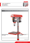
milling machine
Read and take care of the operation manual and the safety instructions!
Technical changes as well as literal and sentence mistakes reserved!
BF 50DIG
Ausgabe: 2011 – Revision
WARNING:FAILURE TO FOLLOW THESE RULES
MAY RESULT IN SERIOUS PERSONAL INJURY
As with all machinery there are certain hazards involved with operation and
use of the machine. Using the machine with respect and caution will
considerably lessen the possibility of personal injury. However, if normal
safety precautions are overlooked or ignored, personal injury to the operator
may result.
This machine was designed for certain applications only. We strongly
recommends that this machine. NOT be modified and/or used for any
application other than for which it was designed. If you have any questions
relative to its application DO NOT use the machine until you have had detail
instruction from your dealer.
SAFETY RULES FOR ALL TOOLS
1.FOR YOUR OWN SAFETY ,READ THIS INSTRUCTION MANUAL BEFORE
OPERATING THE TOOL. Learn the tool's application and limitations as well
as the specific hazards peculiar to it.
2.KEEP GUARDS IN PLACE and in working order .
3.GROUND ALL TOOLS .If tool is equipped with three-prong plug, it
should be plugged into a three-hole electrical receptacle. If an adapter is
used to accommodate a two-prong plug receptacle, the adapter lug must
be attached to a know ground. Never remove the third prong.
4.REMOVE ADJUSTING AND WRENCHES.
Form habit of checking to see that keys and adjusting wrenches are
removed from tool before turning it"on."
5.KEEP WORK AREA CLEAN.
Cluttered
areas and benches invite
accidents.
6.DON'T USE IN DANGEROUS ENVIRONMENT .Don't use power tools in
damp or wet locations, or expose them to rain. Keep work area well- lighted.
7.KEEP CHILDRE AND VISITORS AWAY. All children and visitors should be
keep a safe distance from work area.
8.MAKE WORKSHOP CHILDROOF -with padlocks, master switches, or
by removing starter keys.
9.Don't force tool. It will do the job better and be safer at the rate for which
it was designed.
10.USE RIGHT TOOL .Don't force tool or attachment to do a job for which
it was not designed.
11.WEAR PROPER APPAREL. No loose clothing,gloves,neckties,rings,
bracelets,or other jewelry to get caught in moving parts. Nonslip foot wear
is recommended. Wear protective hair covering to contain long hair.
12.ALWAYS WEAR EYE PROTECTION. Refer to ANSIZ87.1 Standard for
appropriate recommendations. Also use face or dust mask if cutting
operation is dusty.
13.SECURE WORK. Use clamps or a vise to hold work when practical.
It's safer than using your hand and frees both hands to operate tool.
14.DON'T OVERREACH. Keep proper footing and balance at all times.
15.MAINTAIN TOOLS IN TOP CONDITION.
Keep tools sharp and clean for best and safest performance. Follow
instructions for lubricating and changing accessories.
16.DISCONNECT TOOLS before servicing and when changing accessories
such as blades,bits,cutters,ect.
17.USE RECOMMENDED ACCESSORIES.
Consult the owner's manual for recommended accessories .The use of
improper accessories may cause hazards.
18.AVOID ACCIDENTAL STARTING. Make sure switch is in "OFF" position
before plugging in power cord.
19.NEVER STAND ON TOOL. Serious injury could occur if the tool is tipped
or if the cutting tool is accidentally contacted
20.CHECK DAMAGED PARTS. Before further use of the tool, a guard or
other part that is damaged should be carefully checked to ensure that it will
operate properly and perform its intended function check for alignment of
moving parts binding of moving parts, breakage of parts mounting, and any
other conditions that may affect its operation. A guard or other part that is
damaged should be properly repaired or replaced.
21.DIRECTION OF FEED. Feed work into a blade or cutter against the
direction of rotation of the blade or cutter only.
22.NEVER LEAVE TOOL RUNNING UNATTENDED.TURN POWER OFF.
Don't leave tool until it comes to a complete stop.
23.DRUGS,ALCOHOL ,MEDICATION. Do not operate tool while under the
influence of drug, alcohol or any medication.
24.MAKE SURE TOOL IS DISCONNECTED FROM POWER SUPPLY while
motor is being mounted, connected or reconnected.
ADDITIONAL SAFETY RULES FOR MILL DRILL
1.BE SURE drill bit or cutting tool is securely locked in the chuck.
2.BE SURE chuck key is removed from the chuck before turning on power.
3.Adjust the table or depth stop to avoid drilling into the table.
4.SHUT OFF the power ,remove the drill bit or cutting tool, and clean the
table before leaving the machine.
5.CAUTION. When practical , use clamps or a vise to secure workpiece to
keep the workpiece from rotating while the drill bit or cutting tool.
6.WARNING: FOR Your Own Safety Don't wear gloves when operating a
mill/drill.
SPECIFICATIONS:
Drilling capacity
cast iron
45mm
mild steel
32mm
Face mill capacity
80mm
End mill capacity
32mm
Working table size
800mm×240mm
Working table cross travel
230mm
Working table longitudinal travel
560mm
T-Slot size
14mm
Head tilt left right
90°
Spindle taper (option)
MT4
Max distance spindle to table
460mm
Spindle stroke
120mm
Spindle speed(rpm)
(option)
Motor
0.85KW/1.1KW
R8 or ISO30
440mm
Ⅰ
75 180 280 600 1000 1600
Ⅱ
150 360 560 1200 2000 3200
Overall dimension 1090mm×1120mmm×785mm
Packing dimension 850mm×760mm×1150mm
NW/GW Weight
640/700Kg
WARNING:CHANGE SPEED ONLY WHEN MACHINE IS STOPPED
CHANGING THE GEAR BOX OIL
Tilt the head stock over as shown in Fig 1.Open the drain plug to allow the oil
to drain from the opening completely. Then lock the oil drain plug and turn
the head to be upright position. Remove the oil filler plug fill the oil to the
gear box until the oil lever reach the middle of oil fluid lever indicator. Then
lock the plug.
CLEANING
(1) Your machine has been coated with a heavy grease to protect it in
shipping. This coating should be completely removed before operating
the machine. Commercial degreaser, kerosene or similar solvent may be
used to remove the grease from the machine, but avoid getting solvent
on belts or other rubber parts.
(2) After cleaning, coat all bright work with a light lubrication . Lubricate all
points with a medium consistency machine oil.
LUBRICATION:
All ball bearings in your mill/drill are sealed for life ,requiring no lubrication.
Points requiring lubrication are:
(1)Internal spline drive assembly. Keep this area well lubricated with a good
grade grease , insert grease in the hole at the top of spindle pulley spline
driver,lube twice yearly.
(2)A light film of oil applied to the quill and column will reduce wear, prevent
rust, and assure ease of operation.
(3) Quill return spring should receive oil(sae 20) once yearly. Remove cover
plate and apply oil with squirt can or small brush.
(4) IMPORTANT: The gear box should be oiled with a lubricant such as sae
68 oil in level.CHANGE OIL EVERY ONE YEAR.
(5) Apply lubriplate to quill pinion every 90 days.
NOTE: use extreme care when performing this operation and keep hands
clear of pinch points. When using paraffin bar, do this only by turning the
sheaves by hand. Do not apply with motor running.
USE OF MAIN MACHINE PARTS
(1) To raise and lower the head by head handle.
(2) Equipped with an electric switch for tapping operation clockwise or
counterclock wise.
(3) To adjust the quick or slow feeding by feed handle.
(4) To adjust the table left and right travel by table handle wheel.
(5) To adjust the table fore and after travel by table handle wheel.
(6) To operate the spindle handle wheel for micro feed.
(7) To adjust the scale size according to working need.
PRECAUTION FOR OPERATION
Check all parts for proper condition before operation; if normal safety
precautions are noticed carefully, this machine can provide you withstanding
of accurate service.
(1) Before Operation
(a) Fill the lubicant
(b) In order to keep the accurate precision,the table must be free from
dust and oil deposits.
(c) Check to see that the tools are correctly set and the workpiece is set
firmly.
(d) Be sure the speed is not set too fast.
(e) Be sure everything is ready before use
(2) After Operation
(a) Turn off the electric switch.
(b) Turn down the tools.
(c) Clean the machine and coat it with lubricant.
(d) Cover the machine with cloth to keep out the dust.
(3) Adjustment of head
(a) To raise and lower the head, loosen the leaf screw located on the
right side of the raise and lower base. When the desired height is
reached tighten leaf screw to avoid vibration.
(b) Unscrew 3 nuts while the workpiece needs to be bevel turn to the
degrees you wish on the scale ,then screw the 3.
QUILL RETURN SPRING ADJUSTMENT:
Spring tension for return of spindle, after hole drilling, has been pre-set at
the factory .No further adjustment should be attempted unless absolutely
necessary. Adjustment will probably be required if a multiple spindle drilling
or tapping head is used .If adjustment is necessary ,loosen lock screw while
holding quill spring housing .Do not allow the housing to turn in your hand,or
spring will unwind. Turn entire housing assembly clockwise the number of
turns necessary to cause the quill to return to its up position.(NOTE: The flat
of the spring housing pilot is lined up with the spring loading hole on the body
of the spring housing.)Reset lockscrew make sure point of screw mates the
flat on the housing journal.
(1)Preparing for Drilling(see fig.2)(Except addition power feed system).
Turn of the knob make loose the taper body of worm gear and spring
base. Then we decide spindle stroke setting the positive depth stop
gauge for drilling blind hole or free state for pass hole.
(2)Preparing for Milling (see fig.2)(Except addition power feed system).
(a)Adjust the positive depth stop gauge to highest point position.
(b)Turn tight of the knob be use to taper friction force coupling the worm
gear and spring base. Then turning the handle wheel by micro set the
spindle of work piece machining height.
(c)Lock the rack sleeve at the desired height with fixed bolt.
ADJUSTING TABLE SLACK AND COMPENSATE FOR WEAR(see fig.3)
(1) Your machine is equipped with jib strip adjustment to compensate for
wear and excess slack on cross and longitudinal travel.
(2) Clockwise rotation the job strip bolt with a big screw for excess slack
otherwise a little counter clockwise if too tight.
(3) Adjust the jib strip bolt until feel a slight drag when shifting the table.
CLAMPING TABLE BASE AND MACHINE BASE(See Fig.3)
(1) When milling longitudinal feed. It is advisable to lock the cross feed table
travel to insure the accuracy of your work. To do this, tighten the
Fig.3
small leaf screw located on the right side of the table base.
(2) To tighten the longitudinal feed travel of the table for cross feed milling,
tighten the two small leaf screw on the front of the table base.
(3) Adjustable travel stops are provided on the front of the table for control of
cross travel and the desired milling length.
TO CHANGE TOOLS
(1) Removing Face Mill or Drill Chuck Arbor
Loosen the arbor bolt at the top of the spindle shaft approximately 2 turns
with a wrench. Rpa the top of the arbor bolt with a mallet.
After taper has been broken loose, holding chuck arbor on hand and turn
detach the arbor bolt with the other hand.
(2)To install Face Mill or Cutter Arbor
Insert cutter and cutter arbor bolt detach securely, but do not
over-tighten.
(3)Removing Taper Drills
(a) Turn down the arbor bolt and insert the taper drill into the spindle
shaft.
(b) Turn the rapid down handle rod down until the oblong hole in the rack
sleeve appears. Line up this hole with the hole in the spindle. Insert
key punch key through holes and strike lightly lightly with a mallet.
This will force the taper drill out.
SPECIFICATION OF T-SLOT
The size of T-Solt on table as Fig.4.
Fig.4
Maintenance instructions
TROUBLE SHOOTING HINTS
TROUBLE
PROBABLE CAUSE
REMEDY
Excessive Vibration
1.Motor out of balance
2.Bad motor
1.Balance or replace problem motor.
2.Replace motor
Motor stalls
1.Over feeding.
1.Reduce feed rate.
2.Dull drill.
2.Sharpen drill and keep sharp.
3.Motor not building up to 3.Replace or repair motor. Check fuses in all
running speed
three legs on three phase motors and replace
if necessary.
4.Bad motor
4.Replace motor.
Noisy Operation
1.Excessive vibration.
2.Improper quill adjustment.
3.Nosiy spline
4.Noisy motor
1.Check remedy under excessive vibration.
2.Adjust quill.
3.Lubricate spline.
4.Check motor bearings or for loose motor fan.
Drill or Tool heats 1.Excessive speed.
up or burns work.
2.Chips not clearing.
3.Dull tool.
4.Feed reate too slow.
5.Rotation of drill incorrect.
6.Failure to use cutting oil or
coolant(on steel)
1.Reduce speed.
2.Use pecking operation to clear chips.
3.Sharpen tool or replace.
4.Incresase feed enough to clear chips.
5.Reverse motor rotation.
6.Use cutting oil or coolant on steel
Drill leads off
1.No drill spot.
2.Cutting lips on drill off center.
3.Quill loose in head.
4.Bearing play.
1.Center punch or center drill workpiece.
2.Regrind drill.
3.Tighten quill.
4.Check bearings and reseat or replace if
necessary.
Excessive drill
runout or wobble
1.Bent drill.
1.Replace drill. Do not attempt to straighten
2.Bearing play.
2.Replace or reseat bearings.
3.Drill not seated properly in 3.Loosen,reseat and tighten chuck.
chucks.
Work or fixture
comes loose or
spins
1.Failure to clamp workpiece or 1.Clamp workpiece or work holding device to
work holding device to table.
table surface.
Certificate of Inspection
for
Geared Head Milling and Drilling Machine
Model ZX45
Dispatch No.:
HEAD
HEAD PARTS
No.
1
2
3
4
5
6
7
8
9
10
11
12
13
14
15
16
17
18
19
20
21
22
23
24
25
26
27
28
29
30
31
32
33
34
35
36
Qty. Code
1
1
2
2
1
2
1
1
1
1
1
1
1
1
1
1
1
1
2
2
2
1
1
1
1
1
1
3
3
1
1
1
1
1
1
4
20010B
20011B
20018B
20201
20304-1B
20304-2B
20025B
20026B
20027B
20020B
20307B
20105B
20105-1-B
20106B
20108-B
20110-1-B
20111-B
20106-1-B
Name
head body
head body cover
retaining ring
retaining ring
airtight base
airtight ring
motor
screw
washer
plate
arbor bolt cover
arbor bolt cover base
screw
pin
joint
sleeve
nut
bolt
cap
speed lever
pin
oil plug
screw
screw
oil pointer
Ⅰshaft
gear
bearing
bearing
key
Ⅱshaft
gear
gear
gear
gear
bearing
No. Qty. Code
37
38
39
40
40/1
41
42
43
44
45
46
47
48
49
50
52
53
54
55
56
57
58
59
60
61
62
63
64
65
66
67
68
69
70
71
72
1
1
2
1
1
2
1
4
1
1
1
1
1
1
1
1
1
1
1
1
1
1
1
1
1
1
1
1
1
1
1
1
1
1
1
1
20107B
20109-B
20110-2-B
20112-B
20113-B
20019
20104B
20114-B
20116-B
20012
20128
20129
20130
20131
20021
20132
20308
Name
key
key
ball
spring
spring
retaining ring
key
screw
Ⅲ shaft
gear
gear
gear
gear
gear
key
key
spindle sleeve
spindle
bearing
bearing
splined sleeve
gear
retaining ring
feed base
support base
nut
knob
graduated rod
fixed bolt
scale board
lock washer
lock nut
rubber washer
screw
split pin
bolt
No.
73
74
75
76
77
78
79
80
81
82
83
84
85
86
87
88
90
91
92
93
94
95
96
97
98
99
100
101
102
104
105
106
107
108
109
110
Qty. Code
1
1
1
1
1
1
1
1
1
1
1
1
1
1
1
1
1
1
1
1
1
1
1
1
1
1
1
2
1
2
1
1
1
1
1
1
20024B
20133B
62*42*12
20015
20119
20302
20120
20016
20117
20013
20118
20123
20122
20303
20017
20121B
20301B
20306B
20305-1B
20305-2B
20102
20124B
20203B
20202B
20125B
20022-1B
Name
separating ring
oil tight cover
air tight
pin
worm wheel box
worm shaft
worm cover
retaining ring
separating ring
worm wheel
pinion shaft
handle body
spring base
spring cap
spring plate
big ripple handle
graduated plate
handle rod
handle ball
handle wheel
turn handle
screw
screw
washer
bolt
screw
screw
pin
key
screw
fixed bolt
fixed tight block
fixed tight block
adjust handle
lever shaft
lever
No. Qty. Code
111
112
113
114
115
116
117
118
1
2
2
2
2
1
1
1
20204-2B
20204-3B
20126B
20204-1B
20022-2B
Name
lever bracket
retaining ring
screw
lever rod
oil seal
long lever shaft
lever bracket
lever
BASE
BASE PARTS
No.
1
2
3
4
5
6
7
8
9
10
11
12
13
14
15
18
19
20
21
22
23
24
25
26
27
28
29
30
31
35
36
37
38
39
40
41
Qty.
Code
1
1
1
1
1
3
4
1
2
2
2
2
2
1
1
4
3
2
3
6
4
4
4
1
1
1
1
6
6
1
1
1
1
1
1
1
10010
10013
10021
10016
10025
10106
Name
base
column
square flange
raise and lower base
gib strip
screw
bearing
10104
table screw
10102
dial clutch
10111
graduated plate
10301
wheel
20305-1B turn handle
20305-2B screw
10024
nut
10117
nut bracket
screw
pin
10107
screw
8
oil cup
fixed handle
washer
washer
bolt
10120
washer
screw
10119
plate
10124
protecting cover
screw
pin
10011
center base
10012
table
10202
table nut
10203
table base nut
10020
right flange
10019
left flange
10103
table screw
No. Qty. Code
42
43
44
45
46
47
48
49
50
51
52
53
54
55
56
57
58
59
60
61
62
63
64
65
66
67
68
69
71
72
73
74
75
76
77
1
1
2
2
1
2
1
4
2
2
1
2
1
1
2
2
1
1
1
2
2
1
1
7
2
1
1
1
1
4
1
4
1
1
1
10105
Name
dial clutch
fixed block
washer
screw
screw
screw
10022 gib strip
screw
10108 movable fixed block
10109 fixed block support
10023 gib strip
screw M6X16
10017 raise and lower base
10113 shaft
20109 gear
bearing
retaining ring
10015 flange
10116 raise and lower screw
bearing
key6X20
lock washer
lock nut
screw M6X25
pin 6X30
10018 head handle
screw M10X20
turn handle
motor
screw
cover
screw
clutch
gear
power feed
KONFORMITÄTSERKLÄRUNG / CERTIFICATE OF CONFORMITY
EG - KONFORMITÄTSERKLÄRUNG
HOLZMANN MASCHINEN® AUSTRIA GmbH
A-4170 Haslach, Marktplatz 4
Tel.: +43/7289/71562-0; Fax.: +43/7289/71562-4
www.holzmann-maschinen.at
Bezeichnung / name
Fräsmaschine / milling machine
Type(n) / Model(s)
Holzmann BF 50DIG
EG-Richtlinie(n) / EC-Directive(s)
2006/42/EC
2006/95/EC
EN ISO 12100-1:2003
EN ISO 12100-2:2003
EN 12717:2001
EN 13128:2001
Zertifikatnummer(n) / Certificate Number(s)
826040210
Ausstellungsbehörde / issuing authority
Safenet Limited
Pywell Road, Corby, Northants, NN17 5XJ, England
Hiermit erklären wir, dass die oben genannte Maschine den grundlegenden Sicherheits- und
Gesundheitsanforderungen der EG-Richtlinie entspricht. Diese Erklärung verliert ihre Gültigkeit,
wenn Veränderungen an der Maschine vorgenommen werden, die nicht mit uns abgestimmt
wurden.
Hereby we declare that the mentioned machine fulfil the above stated EEC-Directives. Any
manipulation of the machines not authorized by HOLZMANN Maschinen renders this document
invalid.
Haslach, 01.02.2012
Klaus Schörgenhuber, CEO
Ort/place, Datum/date
Unterschrift / sign
GUARANTEE & SERVICE
GUARANTEE (applicable from 09.03.2011)
Please consult our troubleshooting section for initial problem solving. Feel free to contact
your HOLZMANN reseller or us for Customer Support!
Warranty claims based on your sales contract with your HOLZMANN retailer, including
your statutory rights, shall not be affected by this guarantee declaration.
HOLZMANN-MASCHINEN grants guarantee according to following conditions:
A)
The guarantee covers the correction of deficiencies to the tool/machine, at no
charge, if it can be verified adequately that the deficiencies were caused by a material or
manufacturing fault.
B)
The guarantee period lasts 12 months, and is reduced to 6 months for tools in commercial use. The guarantee period begins from the time the new tool is purchased from
the first end user. The starting date is the date on the original delivery receipt, or the
sales receipt in the case of pickup by the customer.
C)
Please lodge your guarantee claims to your HOLZMANN reseller you acquired the
claimed tool from with following information:
>> Original Sales receipt and/or delivery receipt
>> Service form (see next page) filed, with a sufficient deficiency report
>> for spare part claims: a copy of the respective exploded drawing with the required
spare parts being marked clear and unmistakable.
D)
The Guarantee handling procedure and place of fulfilment is determined according
to HOLZMANNs sole discretion in accordance with the HOLZMANN retail partner. If there
is no additional Service contract made including on-site service, the place of fulfilment is
principally the HOLZMANN Service Center in Haslach, Austria.
Transport charges for sendings to and from our Service Center are not covered in this
guarantee.
E)
The Guarantee does not cover:
- Wear and tear parts like belts, provided tools etc., except to intial damage which has to
be claimed immediately after receipt and inital check of the machine.
- Defects in the tool caused by non-compliance with the operating instructions, improper
assembly, insufficient power supply, improper use, abnormal environmental conditions,
inappropriate operating conditions, overload or insufficient servicing or maintenance.
- Damages being the causal effect of performed manipulations, changes, additions made
to the machine.
- Defects caused by using accessories, components or spare parts other than original
HOLZMANN spare parts.
-Slight deviations from the specified quality or slight appearance changes that do not affect functionality or value of the tool.
- Defects resulting from a commercial use of tools that - based on their construction and
power output - are not designed and built to be used within the frame of industrial/commercial continuous load.
F)
Claims other than the right to correction of faults in the tool named in these guarantee conditions are not covered by our guarantee.
G)
This guarantee is voluntary. Therefore Services provided under guarantee do not
lengthen or renew the guarantee period for the tool or the replaced part.
SERVICE
After Guarantee and warranty expiration specialist repair shops can perform maintenance
and repair jobs. But we are still at your service as well with spare parts and/or machine
service. Place your spare part / repair service cost inquiry by filing the SERVICE form on
the following page and send it:
via Mail to [email protected]
via Fax to +43 7248 61 116 6
www.holzmann-maschinen.at
SERVICE FORM / SERVICEFORMULAR
Please tick one box from below / Bitte kreuzen Sie eine der untenstehenden an:
service inquiry
spare part inquiry
guarantee claim
/
/
/
Serviceanfrage
Ersatzteilanfrage
Garantieantrag
1. Senders information (* required) / Daten Antragsteller (* sind Pflichtfelder)
*First name, Family name / Vorname, Nachname
____________________________
*Street, house number / Straße, Hausnummer
____________________________
*ZIP Code, place / PLZ, Ort
____________________________
*Country / Staat
____________________________
*(mobile)Phone / Telefon bzw. Mobiltel.
____________________________
International numbers with country code
* E-Mail
____________________________
Fax
____________________________
2.
Tool information / Geräteinformationen
serial number/Seriennummer:_________*Machine type/Maschinentype:____________
2.1
Required spare parts / benötigte Ersatzteile
Part No° / Ersatzteilnummer Description / Beschreibung
2.2
Problem description / Problembeschreibung
Please describe amongst others in the problem:
What has caused the problem/defect, what was the last activity before you noticed the problem/defect?
For electric problems: Have you had checked your electric supply and the machine already
by a certified electrician?
3.
Number/Anzahl
Additional information
Bitte führen Sie in der Fehlerbeschreibung unter anderem an:
Was hat den Defekt verursacht bzw. was war die letzte durchgeführte Tätigkeit, bevor Ihnen das Problem/der Defekt aufgefallen ist?
Bei Elektrodefekten: Wurde die Stromzuleitung sowie die Maschine bereits von einem
Elektrofachmann geprüft?
/
Bitte Beachten
INCOMPLETELY FILED SERVICE FORMS CANNOT BE PROCESSED!
FOR GUARANTEE CLAIMS PLEASE ADD A COPY OF YOUR ORIGINAL SALES /
DELIVERY RECEIPT OTHERWISE IT CANNOT BE ACCEPTED.
FOR SPARE PART ORDERS PLEASE ADD TO THIS SERVICE FORM A COPY OF
THE RESPECTIVE EXPLODED DRAWING WITH THE REQUIRED SPARE PARTS
BEING MARKED CLEARLY AND UNMISTAKABLE.
THIS HELPS US TO IDENTIFY THE REQUIRED SPARE PARTS FASTLY AND ACCELERATES THE HANDLING OF YOUR INQUIRY.
UNVOLLSTÄNDIG AUSGEFÜLLTE FORMULARE KÖNNEN NICHT BEARBEITET
WERDEN!
GARANTIEANTRÄGE KÖNNEN AUSSCHLIESSLICH UNTER BEILAGE DES
KAUFBELEGES/ABLIEFERBELEGES AKZEPTIERT WERDEN.
BEI ERSATZTEILBESTELLUNGEN LEGEN SIE DIESEM FORMULAR EINE KOPIE
DER BETREFFENDEN ERSATZTEILZEICHNUNG BEI! MARKIEREN SIE DARAUF
DIE BENÖTIGTEN ERSATZTEILE. DIES ERLEICHTERT UNS DIE IDENTIFIZIERUNG UND ERMÖGLICHT SO EINE RASCHERE BEARBEITUNG.
THANK YOU FOR YOUR COOPERATION!
VIELEN DANK!
www.holzmann-maschinen.at