Download PCOUMI2000 Scheda per gestione umidificatore OEM per pCO
Transcript
cod. +050003210 rel. 1.2 - 13.01.2004
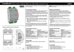
PCOUMI2000 Scheda per gestione umidificatore OEM per pCO / OEM humidifier control board for pCO
Thank you for your choice. We trust you will be satisfied with your
purchase.
Vi ringraziamo per la scelta fatta, sicuri che sarete soddisfatti del
vostro acquisto.
LEGGI E CONSERVA
QUESTE ISTRUZIONI
READ AND SAVE
THESE INSTRUCTIONS
CARATTERISTICHE GENERALI
GENERAL CHARACTERISTICS
Il modulo PCOUMI2000 è un'interfaccia dei controllori elettronici pCO. Permette
di controllare i parametri fondamentali degli umidificatori OEM prodotti da
CAREL (alto livello e conducibilità acqua di alimento nel cilindro, sensore TAM di
assorbimento corrente) direttamente dal regolatore elettronico a microprocessore
pCOB/pCO2/pCO1/pCOC.
I valori raccolti dagli appositi sensori vengono convertiti in segnali compatibili
dagli ingressi presenti nel pCO (per maggiori informazioni si rimanda al relativo
manuale utente del programma applicativo).
The PCOUMI2000 module is an interface for the pCO series electronic
controllers. It is used to control the fundamental operating parameters of the
OEM humidifiers manufactured by CAREL (high water level, water conductivity in
the cylinder, and TAM current sensor) directly from the pCOB/pCO2/pCO1/pCOC
electronic microprocessor controller.
The values read by the special sensors are converted into signals that are
compatible with the inputs on the pCO (for further information, refer to the
corresponding application software user manual).
L’interfaccia PCOUMI2000 rispetto all’interfaccia PCOUMID000 si differenzia per:
- maggior precisione e immunità ai disturbi sia per la misura di conducibilità
che per la misura del sensore di livello;
- il segnale di “alto livello acqua” può essere gestito sia con uscita digitale
che analogica.
The PCOUMI2000 interface differs from the PCOUMID000 interface in the
following ways:
- greater precision and immunity to disturbances for both the conductivity and
the level sensor;
- the “high water level” signal can be managed either by a digital or analogue
output.
Risulterà dunque possibile collegare al controllore sia la scheda PCOUMID000
che la scheda PCOUMI2000, con l’unica accortezza di dover configurare un
opportuno parametro, in modo da permettere al software di utilizzare la corretta
curva di conducibilità.
Consequently, both the PCOUMID000 and the PCOUMI2000 boards can be
connected to the pCO, with the only requirement being that a special parameter
has to be set to allow the software to use the correct conductivity curve.
Dimensioni 4 moduli DIN / Dimensions: 4 DIN modules
TECHNICAL SPECIFICATIONS
CARATTERISTICHE TECNICHE
111
tensione d’ingresso:
potenza assorbita:
morsettiere - sez. conduttori:
condizioni di funzionamento:
condizioni di immagazzinamento:
grado di inquinamento:
dimensioni (mm):
grado di protez. fornito dall’involucro:
classificazione secondo la protezione
contro le scosse elettriche:
24 Vac ± 15%
3 W (5 VA)
min. 0,5 mm2, max. 2,5 mm2
-10T60 °C; 90 % U.R. non condensante
-20T70 °C; 90% U.R. non condensante
normale
110,8 x 70,4 x 60
IP20
Classe II
Tutte le uscite sono protette da cortocircuito.
INSTALLAZIONE
Il montaggio previsto è mediante fissaggio su guida omega (guida DIN
standard).
70
60
Fig. 1
power supply:
power consumption:
terminal blocks - wire cross-section:
operating conditions:
storage conditions:
pollution:
dimensions (mm):
case index of protection:
classification according to protection
against electric shock:
Class II
All outputs are protected against short-circuits.
INSTALLATION
The device is installed by mounting on a standard DIN rail.
DICHIARAZIONI
DECLARATIONS
•
•
•
•
•
•
•
•
PTI dei materiali usati per l’isolamento: >250 V
Periodo di sollecitazioni elettriche delle parti isolanti: Lungo
Categoria di resistenza al calore e al fuoco: D
Categoria (immunità contro le sovratensioni): 2
24 Vac ± 15%
3 W (5 VA)
min. 0.5 mm2, max. 2.5 mm2
-10T60°C; 90 % rH non-condensing
-20T70°C; 90% rH non-condensing
normal
110.8 x 70.4 x 60
IP20
PTI of the insulation materials: >250 V
Period of electric stress across the insulating parts: Long
Category of resistance to heat and fire: D
Category (immunity against voltage surges): 2
Collegamenti / Connections
sonde umidità
humidity probes
dist. max. vedi caratteristiche sonde
for max. distance refer to probe specifications
max. 10 m
controllore
controller
pCO1/pCO2/
pCOC
max. 20 m
interfaccia / interface
pCOUMI2000
cilindro
cylinder
humidifier
input TAM input Cond
input Level
T2 T1 C2 C1
L2
-
G G0 GND TAM Cond Level
L1
O2
dip switch
-
Dig. output Level
analog output
Fig. 3
pCO
Esempio di schema elettrico / Example wiring diagram
G
24 Vac
L1
O2
n.c.
(conduc input) (*)
ID IDC1
(Level input) (*)
B GND
G G0 GND TAM Cond Level
(humidity input) (*)
B +Vdc GND
T2 T1 C2 C1
B
L2
-
sonda umidità
humidity probe
G G0
-
O1
G0
TAM
The connection diagram between the humidifier and the pCO is shown in Fig. 2.
Make the connection respecting the maximum distances recommended and
positioning the cables on dedicated channels, separately from the power cables
and disturbance sources.
ALIMENTAZIONE
POWER SUPPLY
Rispettare le polarità G e G0 del PCOUMI2000 e del controllo pCO quando
l’alimentazione è fornita da uno stesso trasformatore.
The polarity of G and G0 on the PCOUMI2000 and on the pCO controller must
be observed when the power is supplied by the same transformer.
I sensori di rilevamento “livello acqua” o “conducibilità ” dell’umidificatore non
hanno polarità, quindi non necessitano di particolari attenzioni durante il
collegamento alla scheda.
The sensors measuring “water level” or “conductivity ” in the humidifier have no
polarity, and therefore no special attention is required when connecting these to
the board.
Schema di collegamento
Connection diagram
O1
24 Vac
Cond
CONNECTIONS
In generale, il collegamento tra un umidificatore e un pCO può essere
schematizzato come in Fig. 2.
Effettuare il collegamento rispettando le distanze massime riportate e
posizionando i cavi su canaline dedicate, separati dai cavi di potenza e fonti di
disturbo.
Fig. 2
Schema di collegamento / Connection diagram
Level
COLLEGAMENTI
(TAM input) (*)
Morsetti
G
G0
T1
T2
GND
C1
C2
L1
L2
01
02
Level
Cond
TAM
-
Tipo
G
G0
input TAM
Natura
24 Vac
riferimento alimentazione
TAM induttivo 0...2 Vac
GND
input “conducibilità acqua”
riferimento segnali
misura resistiva eseguita
con 0...7 Vac, 5 kHz
misura resistiva eseguita con
0...7 Vac, 5 kHz
switch ON/OFF optoisolato
digitale
input “alto livello acqua”
output “alto livello acqua”
digitale
output “alto livello acqua”
analogico
output “conducibilità acqua”
output TAM
non usato (n.c.)
0...1 Vdc 0-2000 µS/cm
0...1 Vdc 0-2000 µS/cm
0...1 Vdc 0-400% corrente nominale
Cond
TAM
-
Type
G
G0
TAM input
Description
24 Vac
power supply ground
0 to 2 Vac inductive
GND
“water conductivity” input
ground
resistive measurement made
at 0 to 7 Vac, 5 kHz
resistive measurement made
at 0 to 7 Vac, 5 kHz
digital ON/OFF switch,
optically isolated
“high water level” input
“high water level”
digital output
analogue “high water level”
output
“water conductivity” output
TAM output
not used (n.c.)
0 to 1 Vdc 0-2000 µS/cm
0 to 1 Vdc 0-2000 µS/cm
0 to 1 Vdc 0-400% rated current
Dipswitch
Dipswitch
Di default il PCOUMI2000 è settato per lavorare con i pCO , pCO e pCO e i
quattro dip-switch sono posizionati verso l’esterno.
Per il funzionamento con il pCOB i dipswitch vanno spostati tutti quattro verso l’interno.
I dipswitch si trovano sotto lo sportellino inferiore; rimuoverlo con l’utilizzo di un
cacciavite.
2
(*)= gli ingressi e le uscite utilizzati dipendono dal software applicativo
the inputs and outputs used depend on the application software
Terminals
G
G0
T1
T2
GND
C1
C2
L1
L2
01
02
Level
1
C
As default the PCOUMI2000 is set to work with the pCO2, pCO1 and pCOC, and
the four dipswitches are positioned towards the outside.
For operation with the pCOB, all four dipswitches should be moved inwards.
The dipswitches are placed under the lower door; to open it put a screwdriver
under the edge and pry it open.
Fig. 4
CAREL S.p.A.
Via dell’Industria, 11 - 35020 Brugine - Padova (Italy)
Tel. (+39) 0499716611 – Fax (+39) 0499716600
http://www.carel.com – e-mail: [email protected]
CAREL si riserva la possibilità di apportare modifiche o cambiamenti ai propri prodotti senza alcun preavviso.
CAREL reserves the right to modify the features of its products without prior notice.
cod. +050003210 rel. 1.2 - 13.01.2004


