1
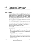
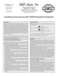
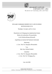
230
Cool On-Column Inlet
Programmable Cool On-Column (PCOC) inlets are designed to allow the
injection syringe to deposit the liquid sample directly into the capillary
column. This is accomplished by the use of an insert which serves to align the
syringe with the capillary column and the syringe needle.
Theory of operation
At injection, liquid sample is introduced directly into the column.
•
•
For manual injections, a duckbill valve (isolation valve) uses inlet
pressure to create a pneumatic seal around the needle.
For automatic injections, the duckbill valve is replaced with a septum
and nut and the septum maintains the pressure seal.
For both manual and EPC inlets, the flow paths are the same; the flow is
divided into two streams. The carrier gas enters the inlet and flows into the
column and additionally provides for a constant septum purge flow regardless
of the column flow rate you use.
Jun 2001
Inlets
Agilent 6890 Gas Chromatograph Service Manual
1 of 20
230
Cool On-Column Inlet
Theory of operation
EPC inlet
An EPC controlled PCOC inlet is a forward pressure regulated system that
provides flow to the column. A pressure sensor is located just ahead of the
inlet and with the proportional valve forms a closed loop electronically
controlled system. In addition, a flow limiting frit (750 mL/min at 50 psi) is
located at the pneumatics entrance. A septum purge regulator (SPR)
maintains septum purge flow between 7 and 15 mL/min.
Flow
limiting Proportional
valve
frit
Pressure
sensor
Septum holder
PS
Septum purge
regulator (not
adjustable)
SPR
Spring and
alignment insert
Purge Vent Flow
15 mL/min
Inlet pressure
control loop
To Detector
Figure 230-1
2 of 20
EPC control
Inlets
Agilent 6890 Gas Chromatograph Service Manual
Jun 2001
Cool On-Column Inlet
Theory of operation
230
Manually controlled inlet
The manually controlled PCOC inlet has a forward pressure regulator (FPR)
that controls the column flow rate. In addition, a forward pressure regulator
with a fixed restrictor (SPR) is used to provide a nominal septum purge flow
rate of 15.0 mL/min. The sample is deposited directly into a capillary column
for analysis.
Forward
pressure
regulator
Septum holder
Septum purge
regulator
SPR
Purge Vent Flow
Spring and
alignment insert
To Detector
Figure 230-2
Jun 2001
Manual control
Inlets
Agilent 6890 Gas Chromatograph Service Manual
3 of 20
230
Cool On-Column Inlet
Replacement procedures
Replacement procedures
Replacing the inlet
WARNING
Turn off the oven and turn off the inlet you are replacing and let them cool
down. Turn off the carrier gas supply pressure, then turn off the main power
switch and unplug the power cord.
1.
From inside the oven, remove the column from the inlet fitting.
2.
From the top of the 6890 GC, remove the blue inlet carrier cover (or the
tray bracket, if installed) and the left side cover.
3.
Unclip the heater/sensor leads from the connector to the left of the inlet
carrier.
4.
Disconnect the inlet plumbing and reroute the plumbing from
underneath the tabs on the left side of the instrument.
EPC inlets: The inlet plumbing terminates in a pneumatics block
connected to the EPC flow manifold with one Torx T-10 screw.
Non-EPC inlets: The inlet plumbing is located in the manual inlet side
carrier. The tubing labelled “C” is connected to the Forward Pressure
Regulator. The line labelled “P” is connected to the septum purge
regulator.
4 of 20
Inlets
Agilent 6890 Gas Chromatograph Service Manual
Jun 2001
Cool On-Column Inlet
Replacement procedures
Figure 230-3
5.
Jun 2001
230
Disconnecting the inlet plumbing block (EPC inlets)
Use a Torx T-20 screwdriver to loosen the three captive screws that attach
the inlet weldment to the top of the inlet carrier.
Inlets
Agilent 6890 Gas Chromatograph Service Manual
5 of 20
230
Cool On-Column Inlet
Replacement procedures
Heater/sensor assembly
Captive screw
Insulation
Figure 230-4
6 of 20
Removing the inlet from the top of the GC
6.
Slide the inlet up out of the inlet carrier. If necessary, you can also slide
the insulation sleeve off of the bottom of the inlet.
7.
Reinstallation is the reverse of removal.
Inlets
Agilent 6890 Gas Chromatograph Service Manual
Jun 2001
Cool On-Column Inlet
Replacement procedures
230
Replacing the heater/sensor assembly
WARNING
Turn off the oven and turn off the inlet you are working on and let them cool
down. Turn off the carrier gas supply pressure, then turn off the main power
switch and unplug the power cord.
1.
Note
If necessary, remove the septum nut, cooling tower and/or needle guide
to provide access to the two screws in the top of the cooling fin.
If desired, you can remove the entire inlet for better access.
Cooling fin
Heater/sensor
assembly
Figure 230-5
2.
Jun 2001
Removing the heater/sensor assembly from the top of the GC
Remove the two Torx T-20 screws securing the cooling fin to the inlet
weldment and remove the fin.
Inlets
Agilent 6890 Gas Chromatograph Service Manual
7 of 20
230
Cool On-Column Inlet
Replacement procedures
3.
Lift the heater/sensor leads out of the weldment channel and lift the
assembly out of the inlet.
4.
Install the new heater/sensor assembly and reassemble the inlet. You may
need to use tweezers to seat the cable back in the channel and fully seat
the heater/sensor in the weldment.
Replacing the inlet EPC flow manifold
WARNING
Turn off the oven and turn off the inlet you are replacing and let them cool
down. Turn off the carrier gas supply pressure, then turn off the main power
switch and unplug the power cord.
All EPC inlets and the ECD detector in the 6890 GC use Type 1 flow manifolds.
8 of 20
1.
Remove the plastic detector cover and the plastic pneumatics cover.
2.
Remove the metal RFI shield and the rear top cover on the back of the GC.
3.
Disconnect the ribbon cable for the manifold from the EPC board. You
may have to remove the adjacent ribbon cable also.
Inlets
Agilent 6890 Gas Chromatograph Service Manual
Jun 2001
Cool On-Column Inlet
Replacement procedures
Figure 230-6
230
Removing the EPC flow manifold
4.
Remove the 1/8-inch Swagelok fitting for the gas supply.
5.
Remove the plumbing block from the front of the manifold (one Torx T-10
screw).
6.
Remove the long screw (Torx T-20) from the top of the manifold and slide
the manifold out of the back of the GC.
7.
Reinstallation is the reverse of removal.
Replacing the supply fitting on a Type 1 EPC flow manifold
See Split/Splitless Inlet for the detailed procedure.
Jun 2001
Inlets
Agilent 6890 Gas Chromatograph Service Manual
9 of 20
230
Cool On-Column Inlet
Leak testing EPC and manual inlets
Leak testing EPC and manual inlets
Preparation
1.
Cool the column to ambient.
2.
Remove the column from the inlet fitting on the inside of the oven.
3.
If the quality of the septum is unknown, replace it now.
Septum retainer
Septum
Spring
Insert
Figure 230-7
4.
Note
10 of 20
Location of septum
Cap the septum purge vent and the inlet’s column fitting. Use solid
(no-hole) Vespel type ferrules 1/8-inch (part no. 0100-1372) and 1/16inch (part no. 5181-7458) with a 1/8-inch Swagelok nut (part no.
5180-4103) and a capillary column nut.
As alternate capping devices, a 1/8-inch Swagelok cap can be used for the
septum purge vent and a capillary column nut with a solid piece of wire the
size of a paper clip and a 0.5 mm ID graphite ferrule may be used for the inlet
column fitting.
Inlets
Agilent 6890 Gas Chromatograph Service Manual
Jun 2001
Cool On-Column Inlet
Leak testing EPC and manual inlets
230
Manual
Septum purge vent
EPC
Figure 230-8
Note
Jun 2001
Septum purge
Capping the bottom of the inlet and septum purge vent
Make sure that the carrier gas source pressure is at least 35 psi. Carrier source
pressure should always be at least 10 psi greater than the desired inlet
pressure.
Inlets
Agilent 6890 Gas Chromatograph Service Manual
11 of 20
230
Cool On-Column Inlet
Leak testing EPC and manual inlets
Performing the leak test—EPC inlets
Note
Be sure that the preparation steps on pages 10 and 11 are complete before
proceeding with this test.
1.
Set the inlet pressure to 25 psi on the keypad.
Press [Front Inlet] or [Back Inlet]. Move to the “Pressure” field and enter “25”.
2.
Wait approximately 15 seconds for equilibration.
If pressure cannot be achieved, either a very large leak is present in
the system, or the supply pressure is not high enough.
3.
Turn the inlet pressure “Off.”
Press [Front Inlet] or [Back Inlet], scroll to the "Pressure"
field, and press [OFF]
4.
12 of 20
Note the “Actual” reading on the display and monitor the pressure for
10 minutes.
Inlets
Agilent 6890 Gas Chromatograph Service Manual
Jun 2001
Cool On-Column Inlet
Leak testing EPC and manual inlets
230
You can use the stopwatch feature of the 6890 GC to monitor the time.
Press [Time] and then [Enter] to start timing, then toggle between
the time and the pressure reading with the [Time] and the [Front
Inlet]/[Back Inlet] keys.
5.
Jun 2001
•
If there is less than 1.0 psi pressure loss (approximately 0.1 psi/
min.), consider the system leak tight.
•
If pressure loss is much greater than1.0 psi, there is a leak that must
be found and corrected. See Correcting leaks later in this section.
When the system is considered leak tight, the caps may be removed, the
column reinstalled, its dimensions configured at keyboard, and the
desired pressure set.
Inlets
Agilent 6890 Gas Chromatograph Service Manual
13 of 20
230
Cool On-Column Inlet
Leak testing EPC and manual inlets
Performing the leak test—manual inlets
Note
Be sure that the preparation steps on pages 10 and 11 are complete before
proceeding with this test.
1.
Turn the pressure controller clockwise until the column head pressure
reaches 25 psi.
2.
Wait 10 minutes for pressure equilibration. The gauge on the front panel
should be stable.
3.
After 10 minutes, shut off the column head pressure by turning the
pressure controller full counter-clockwise.
ON-COL
Pressure gauge
Pressure regulator
Figure 230-9
4.
5.
14 of 20
Inlet manifold
Monitor the pressure gauge for 5 minutes.
•
If there is less than 0.5 psi pressure loss (approximately 0.1 psi/
min.), consider the system leak tight.
•
If pressure loss is much greater than 0.5 psi, there is a leak that must
be found and corrected. See Correcting leaks later in this section.
When the system is considered leak tight, the caps may be removed, the
column reinstalled, and the desired pressure set.
Inlets
Agilent 6890 Gas Chromatograph Service Manual
Jun 2001
Cool On-Column Inlet
Leak testing EPC and manual inlets
230
Leak testing the EPC module only
Occasionally, to track down small leaks, you will need to isolate the EPC
module from the inlet weldment and leak test the EPC module separately.
1.
On the keyboard, turn off pressure to the inlet being tested.
Press [Front Inlet] or [Back Inlet], scroll to the Pressure field
and press [Off].
2.
Use a Torx T-10 screwdriver to remove the screw in the plumbing block
on the front of the module. Remove the plumbing block from the EPC
module, being careful not to lose the O-rings between the block and the
module.
3.
Replace the inlet’s plumbing block with the leak test block (part no.
G1530-20660) from the leak test kit (part no. G1530-60960). Make sure
you install O-rings between the block and the EPC module to create a seal.
The leak test block is a special fitting that plumbs the carrier gas
coming out of the module directly back into the septum purge flow
path on the module. It allows the carrier gas and septum purge to
function normally as if an inlet were present.
4.
Perform the normal leak test for the EPC inlet as described previously in
this section. With the inlet removed, the internal volume is smaller and
a pressure loss of 1.0 psi in 10 minutes is considered leak-free.
Forward pressure valve leaks
Occasionally an increase in pressure, rather than a decrease may be observed.
This is usually due to slight leakage into the module across the forward
pressure control proportional valve. Although slight leaks of this nature do
not create chromatographic problems, they may obscure other small leaks
that do cause problems by allowing air into the system.
To check for internal valve leakage:
1.
Jun 2001
Remove the supply pressure at the carrier inlet fitting, and quickly cap
the fitting with a Solid 1/8-inch Vespel plug and a Swagelok nut.
Inlets
Agilent 6890 Gas Chromatograph Service Manual
15 of 20
230
Cool On-Column Inlet
Leak testing EPC and manual inlets
2.
Check the actual pressure on the display and monitor it for 10 minutes.
Pressure loss should not be greater than 0.5 psi.
Locating leaks
If the EPC module appears to have a leak, you can remove it to locate the
leaky component. The leak test kit (part no. G1530-60960) contains a longer
ribbon cable to allow you to lay the EPC module on the benchtop for testing.
Caution
16 of 20
Be sure to wear an ESD strap grounded to the 6890 GC chassis while
performing this procedure.
1.
Turn off the main power switch.
2.
Disconnect the carrier supply tubing on the inlet fitting.
3.
Remove the top plastic pneumatics cover and the detector cover.
4.
Remove the RFI shield and the top rear cover on the GC.
5.
Disconnect the ribbon cable for the module from the main EPC board.
You may have to remove the adjacent ribbon cable also.
6.
Use a Torx T-20 screwdriver to remove the screw from the top of the
module and slide the module out of the back of the GC.
7.
Connect one end of the leak test ribbon cable (G1530-61370) to the ribbon
cable connector on the EPC module and connect the other end to the
appropriate connector on the EPC board.
8.
Reconnect the carrier supply fitting and set pressures as used in the leak
test.
9.
Lay the EPC module on the lab bench and use an electronic leak detector
to locate the leaky component on the module.
Inlets
Agilent 6890 Gas Chromatograph Service Manual
Jun 2001
Cool On-Column Inlet
Leak testing EPC and manual inlets
230
Ribbon cable from
leak test kit
To gas supply
Figure 230-10
Leak testing the EPC module on the lab bench
10. If the leaky component is serviceable, such as vent/inlet fittings (see the
following diagram of serviceable parts, Figure 230-11), replace them.
Otherwise, replace the EPC module.
Jun 2001
Inlets
Agilent 6890 Gas Chromatograph Service Manual
17 of 20
230
Cool On-Column Inlet
Leak testing EPC and manual inlets
Caution
Aluminum bracket removed
for clarity, DO NOT completely
remove the bracket during
valve replacement.
Aluminum bracket
0-rings
Supply fitting
O-ring
Septum purge fitting
Figure 230-11
EPC module serviceable parts
Correcting leaks
18 of 20
1.
Use an electronic leak detector to check all areas of the inlet that are
potential sources of a leak.
2.
Tighten loose connections to correct leaks, if necessary. You may need
to repeat the leak test.
3.
If the pressure drop is now 0.5 psi or less, you can consider the inlet
system leak-free. If the pressure drops faster than the acceptable rate,
continue to search for leaks and repeat the pressure test.
Inlets
Agilent 6890 Gas Chromatograph Service Manual
Jun 2001
Cool On-Column Inlet
Leak testing EPC and manual inlets
230
Potential leak points
Check the following areas when checking an inlet system for leaks.
In the oven
Make sure the bottom of the inlet is correctly capped.
On the inlet
•
Septum
At EPC module
Jun 2001
•
Three O-rings behind block where pneumatic lines enter module
•
Two O-rings for each valve
•
Septum purge cap
•
Inlet fitting
Inlets
Agilent 6890 Gas Chromatograph Service Manual
19 of 20
230
20 of 20
Cool On-Column Inlet
Leak testing EPC and manual inlets
Inlets
Agilent 6890 Gas Chromatograph Service Manual
Jun 2001