1
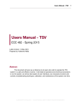
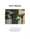
LPRDS-BMS-2010
Lafayette Photovoltaic Research and Development System
Battery Management System
ECE492 – Spring 2010
Lafayette College
Electrical and Computer Engineering Department
User Manual
Preliminary Draft
Contents
1
System Overview .................................................................................................................................. 3
2
System Components.............................................................................................................................. 4
2.1
DC Transfer Switch ...................................................................................................................... 4
2.2
Raw Power Interface (RPI) ........................................................................................................... 4
2.2.1
Indicator LEDs ...................................................................................................................... 4
2.2.2
Isolation Contactor/Ground Fault Detector........................................................................... 4
2.3
Switch Controller (SC).................................................................................................................. 4
2.4
Filter & Inverter Box (FIB) ........................................................................................................... 5
2.5
Energy Storage System (ESS)....................................................................................................... 5
2.5.1
3
2.6
SCADA Interface Box (SIB) ........................................................................................................ 5
2.7
Transformer................................................................................................................................... 5
Getting Started ...................................................................................................................................... 6
3.1
4
Starting Up ............................................................................................................................ 6
3.1.2
Powering a Load ................................................................................................................... 6
3.1.3
Shutting Down ...................................................................................................................... 6
3.2
Emergency Shutdown ................................................................................................................... 6
3.3
Clearing Faults .............................................................................................................................. 6
FAQ....................................................................................................................................................... 7
Calibration..................................................................................................................................... 8
Maintenance .......................................................................................................................................... 9
5.1
6
Normal Operation ......................................................................................................................... 6
3.1.1
4.1
5
Batteries ................................................................................................................................ 5
Battery Maintenance ..................................................................................................................... 9
Schematics/Drawings .......................................................................................................................... 10
1 System Overview
The Lafayette Photovoltaic Research and Development System - Battery Management System (LPRDSBMS) is an experimental system that builds off of the work completed in 2009. It uses a photovoltaic
array mounted on the roof of the Acopian Engineering Center to provide DC power for storage in a
battery array and conversion to AC power by an inverter, all housed in AEC 410. A row of outlets in
room AEC 400 provides power from the inverter using battery storage or a combination of PV power and
batteries depending on the amount of energy required by the load. The system is monitored and controlled
by the SCADA Interface Box (SIB). A safety system opens relays in the Raw Power Interface (RPI) and
Switch Controller (SC) in the event of a system fault. A system shutdown can be scheduled through the
SCADA system. DC power is converted into 120V 60Hz AC power through the Filter & Inverter Box
(FIB).
2 System Components
This section describes all of the main components of the LPRDS-BMS.
2.1 DC Transfer Switch
The DC Transfer Switch can supply power from the PV array to the Sunny Boy inverter, the LPRDS-ETS
system, or disconnect it completely. When the switch is all the way up, it provides power to the Sunny
Boy, when it is all the way down it provides power to the LPRDS-ETS, and when it is in the middle both
are disconnected. The switch should remain locked in position at all times, and should follow standard
Lock-Out Tag-Out (LOTO) procedures.
2.2 Raw Power Interface (RPI)
The RPI provides power from the PV array to Switch Controller. It provides an isolation relay to
disconnect the system from the array in the event of a fault or scheduled shutdown. LEDs on the box
inform the user of the power and fault status of the RPI.
2.2.1 Indicator LEDs
The RPI system has five LEDs visible from the outside. A yellow high voltage indicator light (RPI11)
signifies that there are 30V or more present within the RPI. The green system voltage indicator (RPI10) is
lit whenever the RPI is providing power to the rest of the system. The red light (RPI12) is a fault indicator
and is lit whenever a fault has occurred and the system is in a fault state. The small yellow light (L1) is lit
when 5V power is supplied to the PCB and the small blinking yellow light (L2) blinks when the PIC is
programmed and running.
2.2.2 Isolation Contactor/Ground Fault Detector
The ground fault detector (RPI04) monitors the system for the presence of a fault. It has two alarms.
Alarm 2 opens the isolation contactor (RPI02) and trips the safety circuit whenever a ground fault occurs.
Alarm 1 is a warning that comes on whenever the fault current reaches a percentage of the fault current
level (default 50%).
2.3 Switch Controller (SC)
The SC controls the flow of power to or from the RPI, the ESS, and the FIB. A basic block diagram of
the SC is shown in Figure 1:
Figure 1: SC Block Diagram
2.4 Filter & Inverter Box (FIB)
The FIB converts DC power from the SC into 60Hz 120VAC using an H-Bridge and a filter.
2.5 Energy Storage System (ESS)
The ESS stores power in batteries to use in powering the system and/or the load. It can supply a total of
2KW of power to the system and load, with a maximum of 75W available for system power.
2.5.1 Batteries
The ESS uses 64 lithium iron phosphate (LiFePO4) battery cells to store power. The batteries have a
nominal voltage of 205V. They are 235V when fully charged and can be safely discharged as low as
160V.
2.6 SCADA Interface Box (SIB)
The SIB system monitors voltages, currents, and temperatures at various locations in the system. This
information is monitored for any potential faults and shuts the system down if necessary. Information is
stored for later viewing to monitor the performance of the system.
2.7 Transformer
The one-to-one transformer (T1) provides 120VAC to the load and isolates it from the rest of the system.
It is connected to the outlet strip on the HV cabinet.
3 Getting Started
3.1 Normal Operation
3.1.1 Starting Up
Before powering the LPRDS-BMS, the system must be cleared of all faults and inspected. As stated in the
safety manual (sections 2.7.4 and 3.1), if any high voltage seals are broken, the ground fault system in the
RPI must be retested before resuming operation. If any seals are broken, have a qualified person retest the
ground fault monitor as outlined in the maintenance manual.
The DC transfer switch should be open or providing power to the Sunny Boy and no power should be
provided to the system. Make sure the emergency stop button is pulled into the out position and press the
reset (R) button on the ground fault monitor to ensure it is reset.
Close the DC transfer switch by moving the switch to the lowest position to connect power to the RPI.
Only the person who has locked/tagged out the system may power the system. The 30V indicator (RPI11)
will light if there is 30V or more provided by the PV array, no other LEDs will change. With no load
attached, there may be enough residual voltage across the relay to turn on RPI10.
-Starting up SIB/SCADA
3.1.2 Powering a Load
Designated outlets in AEC400 and the outlet in the atrium of AEC attached to a steel I beam are powered
by the LPRDS-BMS. If there is not enough energy in the system to power a load, the system will
disconnect itself from the load in order to recharge the batteries to a higher level. The system will
automatically reconnect to power a load when there is enough power in the batteries.
3.1.3 Shutting Down
-Service shutdown
-Extended shutdown
3.2 Emergency Shutdown
The emergency shutdown button, located on the side of the high voltage cabinet, immediately trips the
safety circuit and shuts down the system into a safe state when pressed.
-Resetting after an emergency shutdown
3.3 Clearing Faults
-Safety loop
-SCADA
4 FAQ
What solar panels are used and how are they installed?
The PV Array consists of 10 GEPVp-200-MS modules installed on the roof of Acopian
Engineering Center. These modules are connected in a series configuration and placed at a 5 degree angle
facing south. The IV curve for these panels is provided in Figure 1:
Figure 1: IV Curves for GEPVp-200-MS Solar Panels
What are the voltages of the various components of the system, such as the PV Array and the
batteries?
Each PV module is capable of providing over 30V in optimal conditions; however, in nominal
conditions, each panel will provide approximately 25V for a total series voltage of 250V.
64 LiFePO4 are connected in series, each having a charged voltage of 3.2V. The batteries are
connected in series in the ESS rack such that when maintenance is performed on them, only four are
connected for a maximum voltage of 12.8V per cell. When operational and fully charged, the entire ESS
rack provides about 205V @ 10Ah, or 2kW of power.
What is the power budget available to both the system and the load?
The LPRDS-BMS provides approximately 75W for system power (SC, SIB, etc.), and about 2kW
for a load.
4.1 Calibration
The various voltage and current sensors used in the LPRDS-BMS have been characterized and
compensated for offsets and non-linearities. No additional calibration is required for the system.
5 Maintenance
Refer to the Maintenance Manual for proper maintenance procedures not discussed in the User Manual.
5.1 Battery Maintenance
The batteries used in the LPRDS-BMS are Lithium Iron Phosphate Batteries (LiFePO4). These batteries
do not need periodic maintenance like Nickel Metal Hydride or Lead acid. Their chemistry is not
explosive and stable even under under/over charge situations. A typical service time for LiFePO4 is about
6-7 years or 3000 cycles, depending which comes first. If a battery is cycled once per day, it would last
for over 8 years not accounting for capacity loss due to just aging (>3000 cycles).
Even if there are no specific maintenance instructions for LiFePO4 batteries, there are a few good rules of
thumb when it comes to battery conditioning and maintenance:
•
•
•
•
Cycle the battery a few times before using for the first time
Store in a cool dry place
If the memory effect is a problem, cycle the battery a few times every few weeks to undo the
effect
If the batteries need to be stored for a long time unused, then store them in a cool dry place
and charge the batteries before their next use to account for their self discharge.
6 Schematics/Drawings
Figure 1: RPI Module
Key to designators in Figure 1:
A1
Enclosure
A1A
Thumb turn handle with key lock
RPI04
Ground fault monitor - Trips the safety relay in the event of a ground fault. Alarm 2 (Al2)
goes off when the ground current exceeds the tripping point, Alarm 1 (Al1) goes off at half
this level.
RPI04A
Mounting frame for the ground fault monitor.
RPI06A
Safety circuit trip button - Trips the safety circuit.
RPI06B
Safety circuit reset button - Resets the safety circuit.
RPI10
System power indicator - Lights when the RPI relay is closed and power is being provided to
the system.
RPI11
30V indicator - Lights when 30V or more is being supplied by the PV array.
RPI12
Fault indicator light - Lights when there is a fault and the safety relay is tripped.
L1
PCB Power light - Lit when the PCB has 5V power supplied.
L2
PIC light - Blinks to show PIC is programmed and running.
J1
High voltage output receptacle
J2
Supply voltage receptacle
J3
Safety receptacle
J4
RJ45 receptacle
HV
High voltage input