1
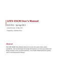
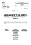
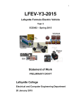
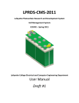
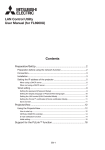
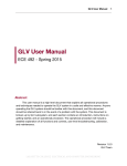
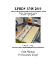
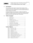
Users Manual - TSV 1 Latest revision: 14 May 2015 Prepared by: Katherine Nellis Abstract This document will serve as a reference to all users who wish to operate the TSV system in a safe and effective manner. It will detail all operational and technical procedures to run the system, as well as fully explain all user interfaces, any necessary functions and controls, troubleshooting techniques, calibration, and maintenance of the system over time. LAFAYETTE COLLEGE │ ELECTRICAL AND COMPUTER ENGINEERING Users Manual - TSV 2 Table of Contents Introduction Reference Materials 3 General Safety Safety Plan 4 System Components Pack Interfaces Charger Cables & Interconnects System Operation 4 5 5 Charge State Troubleshooting 4 Configuration & Set Up Discharge State 8 8 10 Errors Maintenance 11 11 LAFAYETTE COLLEGE │ ELECTRICAL AND COMPUTER ENGINEERING Users Manual - TSV 3 13 Glossary 13 FAQs Introduction The LFEV 2015 team has been tasked with delivering a TSV system consisting of 4 fully functioning battery packs. These four packs are designed to act as the main energy source to a Formula SAE electric vehicle. This document will detail the normal operation of the system involving one fully functioning pack, and any necessary safety precautions or troubleshooting procedures, acting as a continuation of LFEV 2014’s suggestions, along with any new functionality our team has implemented. Reference Materials Charger Technical Manual http://www.us.tdklambda.com/hp/pdfs/Product_manuals/835075002.pdf VSCADA Users Manual http://sites.lafayette.edu/ece492sp15/files/2015/02/UserManual.pdf Safety Plan http://sites.lafayette.edu/ece492sp15/files/2015/02/SafetyPlan.pdf AT90CAN32 Datasheet http://www.atmel.com/images/doc7679.pdf Dynamometer Users Manual http://sites.lafayette.edu/ece492sp15/files/2015/02/DynoUserManual.pdf General Safety Since LFEV 2014’s final design and deliverable was a single complete pack, they provided detailed safety instructions for basic operation of the system, which we as a team chose to extend into this year’s safety considerations. First suggestion is for any user to wear safety glasses during any operation or maintenance on the packs. Each of the 4 system packs contains 7 accumulator cells, each of which stores an incredible amount of energy and, when not properly handled, can produce an electric blast, shock, arc, or other potentially dangerous environment. While safety glasses alone will not prevent these sudden dissipations of energy, they can aid in lessening the damage done should something occur. LAFAYETTE COLLEGE │ ELECTRICAL AND COMPUTER ENGINEERING Users Manual - TSV 4 Another consideration is the size of each accumulator pack within the TSV system. LFEV 2014 documented their pack to weigh in around 50 lbs, and that is not including the other retaining mechanisms we have implemented to hold down the AMS boards and cells. As a results, it is a requirement that each pack be moved by at least two capable individuals at any time. In extension to this, any handling of the pack, whether it be physical movement or inner tinkering, should be a process for two people at a minimum, for safety reasons. The careless mistake of one individual can and may be better prevented by their working partner at the time. Another general thing to take notice on is the fact that certain inner parts of the pack are bound to become heated during operation of the system. Some of these parts will be indicated as such with attentiongrabbing stickers. Safety Plan A final consideration is to follow all steps and guidelines as detailed in the Safety Plan developed by LFEV 2015, which can be accessed through the link provided in the References section of this manual. System Components Accumulator Pack The integral portion of the TSV system is the accumulator pack. This pack models one of the four proposed packs, each of which contains seven lithium iron phosphate (LiFePo ) battery 4 cells, two accumulator isolation relays (AIRs) to prevent any accidental discharging of the pack, and multiple fuses for charging and discharging of the pack, which is controlled by the PacMan, a microcontroller (AT90CAN32), and other circuitry found on the Breakout Board (BoB) within each pack. On top of each cell is a corresponding Accumulator Management System board (AMS), which monitors voltage, current, charge and temperature levels of each cell. The general set up of the pack is a direct result of LFEV 2014’s design, with some mechanical and software modifications included by this year’s team. Two specific additions are the cell retainer casing holding the cells in place within the pack, and the fiberglass barrier which secures the AMS boards to the tops of the cells, to ensure they are not jostled during the expected movement in competition. LAFAYETTE COLLEGE │ ELECTRICAL AND COMPUTER ENGINEERING Users Manual - TSV 5 Figure 1. Accumulator Management System board Figure 2. Breakout Board Interfaces VSCADA While TSV is its own system, it does gather voltage, current, and temperature readings of the packs, and relays all requested data to the central computer system of the LFEV, VSCADA. This communication is achieved through a CAN bus connection. This relationship can be found detailed in better form under VSCADA’s User Manual. Should the VSCADA system be not complete at the time of operation of the TSV system, all level readings can be manually accessed on each pack through its LCD display. Displayed on each pack’s small LCD screen is the following information: 1. Pack Number/ID 2. State of Pack (SOP) 3. State of Charge (SOC) 4. Current level of pack 5. Voltage level of pack 6. Ambient Temperature of pack 7. Occurrence of an error GLV - Tractive System Interface Due to the GLV team’s scoped design of the Tractive System Interface (TSI), the interface between TSV and GLV is simply interconnects that comply with all project and FEV rules and regulations. Assuming proper design and function of their interface, the power from our system will be fed into the TSI through highcurrent discharge connectors, the same parts as used in the previous year’s design. For proper operation, the high voltage and low voltage terminals must be connected to the proper drain (Newark, 44W4361) and source (Newark, 44W4365) ports. LCD Screen There will be a LCD screen on the top of the pack which will display various statuses of the pack. These will be the current pack voltage, the state of charge of each of the cells, the LAFAYETTE COLLEGE │ ELECTRICAL AND COMPUTER ENGINEERING Users Manual - TSV 6 current pack mode, as well as any errors that have been encountered. This LCD screen (DFRobot, DFR0154) will be a smaller screen as compared to the 2014 team’s LCD display. Charger The LFEV 2015 team has opted to save some space in our budget by utilizing the same charger as the LFEV 2014 team. Taken from their design, the charger we will be using is a UL commercial power supply, the specific model being TDKLambda GENH3025. This charger is specified to produce a maximum of 30 Volts DC under a maximum of 25 Amps. The LFEV 2014 team implemented a useful ‘pigtail’ connector to connect the charger and charger cable, which would in turn connect to the charging port of the pack. Necessary steps during the charging process of the packs will be explained further on in this document, however, a more detailed description of the actual operation of the charger can be found in the technical manual listed under the Reference Materials of this report. Figure 3. TDKLambda GENH3025 Charger. Cables & Interconnects Due to both system design and budgeting considerations, LFEV 2015 has opted to reuse many of the physical connections that were implemented by LFEV 2104. This will hopefully allow for ease of transition from one pack to four, as well as allowing us to perform certain viable testing on last year’s pack should restrictions deter us from completing our own new pack. Charging Cable Considering we are reusing the charger provided by LFEV 2014’s design, we are also utilizing the cable for which they connected the pack and charger together. This charging cable allows the current connection to charge the cells of the accumulator pack. Figure 4. Charging Cable. Charging Connector In order to connect the charger and charging cable to our system packs, there is a multicolored LAFAYETTE COLLEGE │ ELECTRICAL AND COMPUTER ENGINEERING Users Manual - TSV 7 (black, green & red) charger port located on the negative end of our pack, referred to as an Anderson PowerPole connector. This port is obviously utilized during the charging operation of this system, but acts as a part of the Safety Loop (SL) otherwise. Figure 5. Charge Port. Figure 6. Dummy Plug for Safety Loop. High-Current Discharge Connectors In terms of interconnect within our system, the pack will be connected with the high (TSV+) and low (TSV) voltage connectors that were previously detailed within the GLVTSI interface description. Each of these can act as a high voltage disconnect point, as they are removable within 10 seconds should something go wrong. There is simply a switch that can be pressed by hand so the plug can be turned and removed. This also complies with FEV rules which state that the plug cannot fall out accidentally. Safety Loop Connectors On each end of every pack, there are 4pin, white connectors that are used to include our system within the SL of the entire LFEV 2015 vehicle system design. Any reference to the SL operation in this manual will be assumed to refer to these connections. Figure 7. TSV+ connector & Safety Loop port. Figure 8. TSV connector. LAFAYETTE COLLEGE │ ELECTRICAL AND COMPUTER ENGINEERING Users Manual - TSV 8 Figure 9. Cables connecting TSV+/ to load. System Operation Configuration As of the most final design, the only implemented configuration of our system is in the addressing assignment of the AMS boards within the pack. Since the LFEV 2015 team chose to modify the PacMan system by replacing the TS81604200 computer with the AT90CAN32 microcontroller, any configuration of the pack can be done in the ‘config.h’ file found within our code repository. Some configurable values include frequencies and baud rates, addresses, and thresholds for voltage, temperature, and current. Since we were unable to fully implement and test the values, any use (or alteration) of the LFEV 2015 values should be widely researched, and approved by the current course instructors. Discharge State The pack is described to be in a state of discharge under any circumstances in which the AIRs are closed, and current is being drawn from the discharge interconnects. To ensure the safest conditions within this state, the following procedures should be practiced. Setup In order to safely discharge the pack within the TSV system, it is crucial that no errors are displayed on the LCD screen. Should there be any errors present, no operation of the pack should occur until the error is addressed. Please refer to the ‘Troubleshooting’ section of this manual in order to continue. 1. First connect the pack to the SL by pushing in the SL connector until it clicks. This loop must be closed in order for the pack to operate; an open SL infers that there is something wrong within the system and therefore no TSV power should be supplied to LAFAYETTE COLLEGE │ ELECTRICAL AND COMPUTER ENGINEERING Users Manual - TSV 9 the motor. If the pack is being used separate from the entire LFEV system, this connection may seem futile but is still necessary. 2. Next connect the communication link by attaching the CAN bus cable to the corresponding port by pushing it in until it clicks. Although not directly correlated to the discharge state of the pack, this connection is necessary for any data communication between the packs and VSCADA, and therefore is highly encouraged. 3. Next attach the safety plug to the port used for charging by pushing in the connector until it clicks. If the charging cable is still attached to the pack it must be removed and replaced with the safety plug before discharge can begin. 4. Connect the pack to the load using the high current discharge connectors. Push each plug on straight, then rotate the plug clockwise until it clicks. For further information, refer to LFEV 2015 Dynamometer (Dyno) team’s User Manual, which can be found listed under the Reference Materials of this document. Discharging In case of any emergency, terminate discharge by deactivating the SL to the system. 1. Activate the SL. The AIRs should close with an audible click. If not, this may indicate some error or damage to the system. 2. Activate the load in accordance with the Operational Procedures set by the Dyno’s User Manual. The current being drawn from the pack will be indicated on the corresponding LCD display. 3. The pack will continue to discharge until a threshold is detected by the PacMan system within the pack. This could be low cell voltage, or a high temperature. 4. If an error occurs during discharge, logic and circuitry within the BoB will open the SL and the discharge will cease. VSCADA’s monitoring capabilities should also perform this task. The SL cannot be reset until that error is resolved. Please refer to the ‘Troubleshooting’ section of this manual to fix said errors. End of Use When done using the packs within a discharging state, it is recommended to disassemble the system in the following manner to ensure safety. 1. Disconnect the pack from the load before continuing, refer to Dyno’s User Manual for specific instructions. The high current discharge connectors must not be removed while still connected to a load. 2. Deactivate the SL so as not to force the AIRs open. That functionality is reserved for emergency situations. 3. Disconnect the SL, CAN bus, and discharger connectors. 4. If applicable, store the singular pack in a dry and secure place. LAFAYETTE COLLEGE │ ELECTRICAL AND COMPUTER ENGINEERING Users Manual - TSV 10 Charge State Setup In order to properly charge the pack within our TSV system, it is necessary that the charger being used is the charger detailed within the document, or one of equal caliber and requirements. Again, it is crucial that no errors be displayed on the pack’s LCD screen before attempting charging. Should an error be present, please refer to the ‘Troubleshooting’ section of this manual before continuing. 1. Connect the AC mains cable to the charger and plug it into a grounded, 120VAC power source, such as a standard wall socket. 2. Turn on the charger using the AC mains power switch. 3. Next connect the communication link by attaching the CAN bus cable to the corresponding port by pushing it in until it clicks. Although not directly correlated to the charging state of the pack, this connection is necessary for any data communication between the packs and VSCADA, and therefore is highly encouraged. 4. Remove the safety plug from the charging port on the pack. Doing so opens the SL, and ensures that the pack will not be within the charging and discharging state simultaneously. 5. Next attach the charging cable to the charger by pushing one end into the pigtail connector until it clicks. 6. Next attach the other end of the charging cable to the pack by pushing the connector into the port until it clicks. Charging The pack being charged should automatically detect the presence of the charger at connection; as a result the relays associated with charging will close, and the pack will begin to charge. End of Use Charging of the pack can be terminated in multiple ways: 1. The PacMan system will detect that the pack is fully charged, the charging relays will open, and the flow of current to the cells will cease. 2. Should the charger be disconnected at any time, even before the microcontroller determines charge complete, charging will cease. 3. In the case of an error, charging will automatically terminate. After referencing the LCD display to determine and fix the error, it is required that the charger be disconnected, and then reconnected, in order to resume charging. LAFAYETTE COLLEGE │ ELECTRICAL AND COMPUTER ENGINEERING Users Manual - TSV 11 Troubleshooting Error Codes Should any error occur during any state of operation with the TSV system, the LCD displays on each pack will contain information about the state of the system. The following error codes detail the actual error associated with each shortcode. Any updated error functionality implemented by LFEV 2015 will be added to this manual in a timely fashion. VOLT_OVER_ERR: This error indicates that the PacMan system has checked the voltage threshold of the pack, and that the voltage detected is over the upper voltage threshold set during configuration. VOLT_UNDER_ERR: This error indicates that the PacMan system has checked the voltage threshold of the pack, and that the voltage detected is under the lower voltage threshold set during configuration. TEMP_ERR_FUSE: This error indicates that the PacMan system has checked the temperature of the sensor at the fuse in the pack, and that reading was above the temperature threshold set during configuration. TEMP_ERR_AMB: This error indicates that the PacMan system has checked the temperature of the ambient temperature sensor in the pack, and that reading was above the temperature threshold set during configuration. Maintenance Although the TSV system is intricate and contains a plethora of parts within each pack, there are multiple useraccessible parts that can be maintenanced or replaced without having to fully disassemble the packs, or can be done without full knowledge of the system design. Fuses Charging Fuse Many things can occur during the charging state of the system that could result in an unsafe operating environment. As a result, these fuses protect the charging circuit and can often be blown or damaged. Should this happen, the following procedure is recommended for their repair: 1. Disconnect all connectors from the pack: a. Safety Loop b. CAN Bus c. Discharge connectors d. Charge connector 2. Remove the end cap from the fuse holder by rotating counterclockwise, then pulling straight out. The fuse will come out with the cap. LAFAYETTE COLLEGE │ ELECTRICAL AND COMPUTER ENGINEERING Users Manual - TSV 12 3. If the fuse cartridge is broken or damaged, it is possible that small shards of material are lodged in the holder. In this case, the entire fuse holder should be replaced. 4. The fuse is a 15amp, 3AB ceramictube type cartridge fuse. Because the fuse element cannot be visually inspected, the fuse must be continuitytested with a multimeter. 5. If the fuse reads <1 ohm, it is still good. 6. If the fuse reads >1 ohm, it is blown and must be replaced. 7. If the fuse is blown, it must be replaced only by Littelfuse part number 0505030.MXP or an equivalent that is approved. This fuse has a 250V AC, 60V DC interrupt rating which is necessary to ensure full protection of the system and operator. IMPORTANT: Although physically interchangeable, standard 3AG glasstube fuses available at hardware stores are NOT acceptable substitutes in this system. 8. If the fuse is good, reinstall it by placing it in the end cap and replacing the end cap in the holder. The fuse can be inserted either direction. The other fuse should be inspected in the same fashion. Discharging Fuse With all four packs fully interconnected and charged, the TSV system can supply up to around 100 Volts of power, and as a result can blow the fuse in its primary current path. Should this occur, the following procedure is recommended for repair: 1. Disconnect all connectors from the pack: a. Safety Loop b. CAN Bus c. Discharge connectors d. Charge connector 2. Face the pack so the negative terminal is on your right. Remove the side enclosure panel. The fuse holder is accessible only from this side. 3. Remove the bolts holding the fuse to the holder using an insulated wrench. Take care to keep track of the bolts and washers. 4. The fuse is a 200amp Class T fuse. Because the fuse element cannot be visually inspected, the fuse must be continuitytested with a multimeter. 5. If the fuse reads <1 ohm, it is still good. 6. If the fuse reads >1 ohm, it is blown and must be replaced. 7. If the fuse is blown, it must be replaced only by Mersen part number A3T200. This fuse has a 160V, 50kA DC interrupt rating which is necessary to ensure full protection of the system and the operator. 8. If the fuse is good, reinstall it by attaching it to the fuse holder using the bolts and washers removed in Step 2. LAFAYETTE COLLEGE │ ELECTRICAL AND COMPUTER ENGINEERING Users Manual - TSV 13 Glossary AIR → Accumulator Isolation Relay AMS → Accumulator Management System BoB → Breakout Board CAN → Controller Area Network Dyno → Dynamometer GLV → Grounded Low Voltage LCD → Liquid Crystal Display LFEV → Lafayette Formula Electrical Vehicle PacMan → Pack Manager SAE → Society of Automotive Engineers SL → Safety Loop SOC → State of Charge SOP → State of Pack TSI → Tractive System Interface TSV → Tractive System Voltage VSCADA → Vehicle Supervisory Control and Data Acquisition FAQs How many volts does the TSV system supply? One accumulator pack supplies around 24 V. In a system with four packs connected in series, there can be around 100 V supplied. How many amps are drawn from the TSV system? The amount of current drawn from the accumulator packs is dependent on the load to which it is connected. What type of battery cells does TSV use? The type of cell utilized in our design are lithium iron phosphate (LiFePO ) prismatic 4 cells. The datasheet for this product can be accessed here: http://www.batteryspace.com/prodspecs/6334.pdf How much does each pack weigh? The accumulator pack weighs around 50 lb (~22.7 kg). As such it should only be moved by at least two authorized persons. LAFAYETTE COLLEGE │ ELECTRICAL AND COMPUTER ENGINEERING