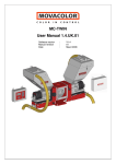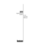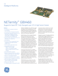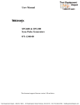
1
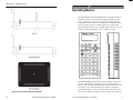
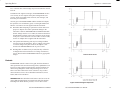
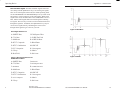
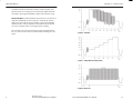
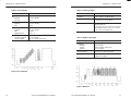
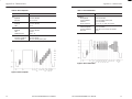
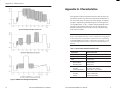
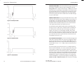
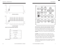
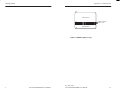
User Manual
TSG 90 PATHFINDER
NTSC Signal Generator
070-8964-00
Please check for change information at the rear
of this manual.
30
TSG 90 PATHFINDER User Manual
First Printing November 1993
Revised March 1994
Copyright E Tektronix, Inc., 1992, 1993. All rights reserved.
Printed in U.S.A. Tektronix products are covered by U.S. and foreign patents, issued and pending.
Information in this publication supersedes that in all previously
published material. Specifications and price change privileges reserved. The following are registered trademarks: TEKTRONIX and
TEK.
For further information, contact: Tektronix, Inc., Corporate Offices,
P.O. 500, Beaverton, Oregon, 97077
TSG 90 PATHFINDER User Manual
29
Appendix C: User Service
1.
Auto power-down; use the left (A ) or right ( ") arrow key to
toggle between enabled and disabled.
2.
Battery type; use the left (A ) or right ( ") arrow key to toggle
between disposable or rechargeable.
3.
Factory Reset; press the Enter button to reset the instrument to
the factory defaults. WARNING: All user selections will be lost.
4.
LCD Diagnostic; press the A key to turn all segments on, and
press the " key to turn all segments off.
5.
Tone LVL0; used in setting the 0 dBu tone level. See the
Service manual (Tektronix p/n 070-8706-00) for the audio
amplitude adjustment procedure.
6.
Tone LVL4; used in setting the 4 dBu tone level. See the
Service manual for the audio amplitude adjustment procedure.
7.
Tone LVL8; used in setting the 8 dBu tone level. See the
Service manual for the audio amplitude adjustment procedure.
Preventive Maintenance
Under average conditions, the PATHFINDER should receive preventive maintenance every 2000 hours. This is approximately one
year of operation. Preventive maintenance includes cleaning, visual
inspection, a performance check and, if necessary, calibration. See
the Service manual for performance verification and adjustment
procedures.
CAUTION. The PATHFINDER case is made of molded plastic. Do
not allow water to get inside of any enclosed assembly or component. Do not clean any plastic materials with organic cleaning solvents—benzene, toluene, xylene, acetone, or similar compounds—
because they may damage the plastic.
28
TSG 90 PATHFINDER User Manual
Warranty
Tektronix warrants that the TSG 90 PATHFINDER NTSC Signal Generator will be free from defects in materials and workmanship for a period of
one (1) year from the date of shipment. If this product proves defective
during the warranty period, Tektronix, at its option either will repair the
defective product without charge for parts and labor, or will provide a
replacement in exchange for the defective product.
In order to obtain service under this warranty, Customer must notify Tektronix of the defect before expiration of the warranty period and make
suitable arrangements for the performance of service. Customer shall be
responsible for packaging and shipping the defective product to the service center designated by Tektronix, with shipping charges prepaid. Tektronix shall pay for the return of the product to Customer if the shipment
is to a location within the country in which the Tektronix service center is
located. Customer shall be responsible for paying all shipping charges,
duties, taxes, and any other charges for products returned to any other
locations.
This warranty shall not apply to any defect, failure or damage caused by
improper use or improper or inadequate maintenance and care. Tektronix
shall not be obligated to furnish service under this warranty a) to repair
damage resulting from attempts by personnel other than Tektronix representatives to install, repair or service the product; b) to repair damage
resulting from improper use or connection to incompatible equipment; c)
to repair any damage or malfunction caused by the use of non-Tektronix
supplies; or d) to service a product that has been modified or integrated
with other products when the effect of such modification or integration
increases the time or difficulty of servicing the product.
This warranty is given by Tektronix with respect to this product in
lieu of any other warranties, express or implied. Tektronix and its
vendors disclaim any implied warranties of merchantability or fitness for a particular purpose. Tektronix’ responsibility to repair or
replace defective products is the sole and exclusive remedy provided
to the customer for breach of this warranty. Tektronix and its vendors will not be liable for any indirect, special, incidental, or consequential damages irrespective of whether Tektronix or the vendor
has advance notice of the possibility of such damages.
TSG 90 PATHFINDER User Manual
i
Appendix C: User Service
Battery Hints
For optimal battery life and capacity, use the rechargeable NiCad
battery pack (Tektronix p/n 119-4488-00) in full charge/discharge
cycles. In other words, fully discharge the battery pack before recharging, and then charge the battery pack until fully charged,
approximately 16 hours. A new battery pack will take a few charge/
discharge cycles to reach full capacity.
WARNING. Install or replace batteries only with the instrument
switched OFF, and the AC adapter disconnected.
Replace the batteries only with standard AA batteries (1.2–1.5 V,
nominal), or with a Tektronix rechargeable battery pack (p/n
119-4488-00).
Setting the Battery Type and the Auto Power Down functions in the
diagnostic menu also has an impact on battery life. The battery
types are disposable (Alkaline) or rechargeable (NiCad). Setting the
battery type changes the voltage level that causes the battery low
message to be displayed, and also changes the cut-off voltage for
instrument operation.
The Auto Power Down function, when enabled, shuts the PATHFINDER off when there is no keypress for approximately 10 minutes, to conserve battery life. Auto Power Down is indicated, when
enabled, by a rotating line in the upper right corner of the display.
The Diagnostic Menu
To enter the diagnostic menu, hold the Lock Out button down while
turning the instrument on. To exit the diagnostic menu and resume
normal instrument operation, press any of the rectangular buttons at
the top of the keypad.
The diagnostic menu items are listed below. Use the up (Y) and
down (B) arrow keys to move up and down the list.
ii
TSG 90 PATHFINDER User Manual
TSG 90 PATHFINDER User Manual
27
Appendix B: Replaceable Parts
Contents
Warranty . . . . . . . . . . . . . . . . . . . . . . . . . . . . . . . . . . . . . .
List of Figures . . . . . . . . . . . . . . . . . . . . . . . . . . . . . . . . .
List of Tables . . . . . . . . . . . . . . . . . . . . . . . . . . . . . . . . . .
i
iii
iv
Getting Started . . . . . . . . . . . . . . . . . . . . . . . . . . . . . . . . . . .
1
Operating Basics . . . . . . . . . . . . . . . . . . . . . . . . . . . . . . . . . .
Controls . . . . . . . . . . . . . . . . . . . . . . . . . . . . . . . . . . . . . .
Shift/Shift Lock. . . . . . . . . . . . . . . . . . . . . . . . .
Lock Out. . . . . . . . . . . . . . . . . . . . . . . . . . . . . . .
Bars and Other Signals. . . . . . . . . . . . . . . . . . . .
ID On/Off and ID Menu. . . . . . . . . . . . . . . . . . .
ID Edit and ID Position. . . . . . . . . . . . . . . . . . .
Tone On/Off and Tone Menu. . . . . . . . . . . . . . .
Recall and Store. . . . . . . . . . . . . . . . . . . . . . . . .
3
4
4
5
6
7
7
7
8
Appendix A: Characteristics . . . . . . . . . . . . . . . . . . . . . . . .
9
Appendix B: Replaceable Parts . . . . . . . . . . . . . . . . . . . . . .
25
Appendix C: User Service . . . . . . . . . . . . . . . . . . . . . . . . . . .
Battery Hints . . . . . . . . . . . . . . . . . . . . . . . . . . . . . . . . . .
The Diagnostic Menu . . . . . . . . . . . . . . . . . . . . . . . . . . . .
Preventive Maintenance . . . . . . . . . . . . . . . . . . . . . . . . . .
27
27
27
28
List of Figures
Figure 1: Multiburst . . . . . . . . . . . . . . . . . . . . . . . . . . . . .
Figure 2: NTC7 Composite . . . . . . . . . . . . . . . . . . . . . . .
Figure 3: NTC7 Combination . . . . . . . . . . . . . . . . . . . . .
Figure 4: FCC Composite . . . . . . . . . . . . . . . . . . . . . . . .
Figure 5: SMPTE Color Bar Signal Components . . . . . .
Figure 6: 75% Bars . . . . . . . . . . . . . . . . . . . . . . . . . . . . . .
Figure 7: 5-Step Staircase (Gray Scale) . . . . . . . . . . . . . .
26
TSG 90 PATHFINDER User Manual
Rev Mar 1994
TSG 90 PATHFINDER User Manual
11
12
13
14
16
17
17
iii
head a
Figure 8: Red Field . . . . . . . . . . . . . . . . . . . . . . . . . . . . . .
Figure 9: Field Square Wave . . . . . . . . . . . . . . . . . . . . . .
Figure 10: 50 IRE Flat Field . . . . . . . . . . . . . . . . . . . . . .
Figure 11: 0 IRE, No Burst . . . . . . . . . . . . . . . . . . . . . . .
Figure 12: Black Burst . . . . . . . . . . . . . . . . . . . . . . . . . . .
Figure 13: SINX/X . . . . . . . . . . . . . . . . . . . . . . . . . . . . . .
Figure 14: Convergence Signal Components . . . . . . . . . .
Figure 15: Matrix . . . . . . . . . . . . . . . . . . . . . . . . . . . . . . .
Figure 16: Safe Area Signal Components . . . . . . . . . . . .
Figure 17: SNG Bars (Option 1J only) . . . . . . . . . . . . . .
17
18
18
18
19
19
20
20
22
23
Appendix B: Replaceable Parts
The following Replaceable parts for the TSG 90 PATHFINDER are
available through your local Tektronix, Inc. field office or representative.
It is important when ordering parts to include the following information in your order: Part number; instrument type and number;
instrument serial number; and modification number, if applicable.
Description
List of Tables
Table 1:
Table 2:
Table 3:
Table 4:
Table 5:
Table 6:
Table 7:
Table 8:
Table 9:
iv
Physical Data and Environmental Limits . . . . .
Power Requirements/Battery Life . . . . . . . . . . .
Test Signal Generator—General Characteristics
Audio Tone Output . . . . . . . . . . . . . . . . . . . . . .
Multiburst Test Signal . . . . . . . . . . . . . . . . . . . .
NTC7 Composite . . . . . . . . . . . . . . . . . . . . . . . .
NTC7 Combination . . . . . . . . . . . . . . . . . . . . . .
FCC Composite . . . . . . . . . . . . . . . . . . . . . . . . .
Remaining Test Signals . . . . . . . . . . . . . . . . . . .
9
10
10
11
11
12
13
14
15
Rev Mar 1994
TSG 90 PATHFINDER User Manual
Tektronix Part No.
Reference Card
063-1449-00
Service Manual (Optional accessory)
070-8706-00
Rechargeable Battery Pack (Optional accessory)
119-4488-00
Carrying Pouch
016-1229-00
AC Adapter
119-4538-00
Case Assembly, Top
614-0915-00
Case Assembly, Bottom
614-0913-00
Battery Door
200-4075-00
LCD Display
119-4506-00
Rear Panel Assembly
333-4065-00
Fuse 1.5A, 125V
159-0153-00
TSG 90 PATHFINDER User Manual
25
Appendix A: Characteristics
Getting Started
Please note the following statements before using your new TSG 90
PATHFINDER.
CAUTION. Attempting to operate the TSG 90 with an improper AC
adapter can result in permanent damage to the instrument. To avoid
damage, USE ONLY AN APPROPRIATE DC POWER SOURCE:
Voltage must be 9 to 15 VDC; the connector must have the NEGATIVE contact in the center; and open-circuit voltage of the power
source must not exceed 18 VDC.
For best results, use the AC adapter that is supplied with the instrument. If the supplied adapter is incorrect for the local AC power
supply, please contact your nearest Tektronix representative.
WARNING. Install or replace batteries only with the instrument
switched OFF and the AC adapter disconnected.
Replace the batteries only with standard AA batteries (1.2–1.5 V,
nominal), or with a Tektronix rechargeable battery pack (p/n
119-4488-00).
If you have any questions regarding the operation of this instrument, please contact your nearest Tektronix representative or field
office. In the United States and Canada, you may also call the Tektronix information number, 1-800-TEK-WIDE (1-800-835-9433),
between 8:00 am and 5:00 pm Pacific time.
24
TSG 90 PATHFINDER User Manual
TSG 90 PATHFINDER User Manual
1
Getting Started
Appendix A: Characteristics
LINES
21
30 IRE Flat Field
163
164 – 198
199 – 209
210
SMPTE Color Bars
SMPTE IYQB
30 IRE Flat Field
262
Figure 17: SNG Bars (Option 1J only)
2
TSG 90 PATHFINDER User Manual
Rev Mar 1994
TSG 90 PATHFINDER User Manual
23
Appendix A: Characteristics
Operating Basics
The TEKTRONIX TSG 90 PATHFINDER TV Signal Generator is
designed for ease of operation and outstanding portability. It provides a complement of 16 NTSC test signals, including the Safe
Area signal. It also provides 13 selectable audio frequencies from
50 Hz to 20 kHz, a 50 Hz to 20 kHz audio sweep, and an audio
click channel ID. The two stereo AUDIO outputs may be set to one
of three selectable amplitudes: 0 dBu, +4 dBu, or +8 dBu.
Figure 16 (cont.): Safe Area Signal Components
22
TSG 90 PATHFINDER User Manual
The PATHFINDER provides character ID capability, as well, storing up to eight messages consisting of two 16 character lines of
text. Any one of these text messages may be inserted into the video
test signal, or up to four of them may be cycled in a continuous
loop (displaying for 1 to 9 seconds each) in any order. These messages may be displayed anywhere in the safe action area of the pic-
TSG 90 PATHFINDER User Manual
3
Operating Basics
Appendix A: Characteristics
ture, or the first line of the message may be moved into the vertical
interval.
In addition to the eight text messages, the PATHFINDER can also
store as many as four complete front-panel configurations (user
presets), which can include menu selections, text messages, and
tone and cycle information.
You may power the PATHFINDER with the standard AC adapter,
the optional 9.6 V NiCad battery pack, or with eight standard AA
batteries. AA batteries are not supplied with the instrument.
H
Remember that attempting to operate the TSG 90 with an improper AC adapter can result in permanent damage to the
instrument. USE AN APPROPRIATE DC POWER SOURCE
ONLY: Voltage must be 9 to 15 VDC; the connector must have
the NEGATIVE contact in the center; and open circuit voltage
of the power source must not exceed 18 VDC. For best results,
use the AC adapter that is supplied with the instrument.
H
The optional NiCad battery pack may be recharged without
removing it from the instrument. The AC adaptor will provide
a “trickle” charge to the pack whenever the adaptor is connected to the PATHFINDER and an AC power source.
H
Rechargeable AA batteries may be used, but they will not be
recharged when in the instrument. To recharge AA batteries,
remove them from the PATHFINDER and use any appropriate
charger.
Controls
PATHFINDER controls consist of a keypad, which has buttons to
make operational selections and entering menus; alphanumeric buttons for text entry and test signal selection; and arrow buttons for
maneuvering through the menus and positioning text on screen.
There is an enter button in the center of the arrow keys, used in
menu selections. There is also a Shift/Shift Lock button, an ON
button, and a Lock Out button.
Shift/Shift Lock. The Shift/Shift Lock button is used to access the
upper (shifted) nomenclature associated with each of the buttons,
including itself. When Shift is pressed, a reverse video S is dis-
4
TSG 90 PATHFINDER User Manual
Figure 16: Safe Area Signal Components
TSG 90 PATHFINDER User Manual
21
Appendix A: Characteristics
Operating Basics
Figure 14: Convergence Signal Components
played in the lower right corner of the LCD display, indicating that
the next keystroke will use the shifted nomenclature. If the next
keystroke is the Shift button again, then the keypad is locked into
the shift mode and all keystrokes will use the shifted nomenclature.
The LCD display shows a reverse video SL, indicating that shift
lock is active. Shift Lock is cancelled by pressing the Shift button a
third time.
Lock Out. The Lock Out button is used to disable the keypad.
While locked out, pressing any key (except Lock Out or ON) produces the message “press Lock Out” on the LCD display and has
no other effect. While in Lock Out mode, a lock symbol (padlock
icon) appears in the lower right corner of the LCD display.
Holding the Lock Out button down while switching the instrument
on will invoke the diagnostic menu. See Appendix C (page 27) for
more information.
Figure 15: Matrix
20
TSG 90 PATHFINDER User Manual
TSG 90 PATHFINDER User Manual
5
Operating Basics
Appendix A: Characteristics
Bars and Other Signals. The Bars and Other Signals buttons are
used, along with the alphanumeric keys, for selecting test signals.
This occurs in the Signal Select mode; the default operating mode
for the PATHFINDER. The PATHFINDER powers up in this mode,
and returns to it after exiting any of the other modes. While in the
Signal Select mode, the Bars button selects SMPTE Bars and 75%
Bars, and the Other Signals button scrolls through the remaining
test signals. The arrow keys will also scroll forward and backward
through the signal list. In addition, the alphanumeric keys may be
used to select signals directly, eliminating the need to scroll
through all the signals to get to the one you want:
Figure 12: Black Burst
Direct Signal Selection List
A=SMPTE Bars
I=Field Square Wave
B=75% Bars
J=50 IRE Flat Field
C=Multiburst
K=0 IRE No Burst
D=NTC7 Composite
L=Black Burst
E=NTC7 Combination
M=SIN X/X
F=FCC Composite
N=Convergence
G=5 Step
O=Matrix
H=Red Field
P=Safe Area
Option 1J Direct Signal Selection List
SN B021565 and Above
6
A=SMPTE Bars
I=Red Field
B=75% Bars
J=Field Square Wave
C=SNG Bars
K=50 IRE Flat Field
D=Multiburst
L=Black Burst
E=NTC7 Composite
M=SIN X/X
F=NTC7 Combination
N=Convergence
G=FCC Composite
O=Matrix
H=5 Step
P=Safe Area
Rev Mar 1994
TSG 90 PATHFINDER User Manual
Figure 13: SINX/X
TSG 90 PATHFINDER User Manual
19
Appendix A: Characteristics
Operating Basics
ID On/Off and ID Menu. The ID On/Off button toggles the character
ID messages (captions) on and off. The LCD display will read
ID=off, ID=on for a single text ID message, or ID=cyc if cycle has
been turned on in the ID Menu. The ID Menu is accessed by pressing the Shift button before pressing the ID On/Off button. The ID
Menu allows the ID cycle to be turned on or off, sets the display
time for the captions, and selects which of the stored ID messages
to cycle in what order.
ID Edit and ID Position. Pressing the ID Edit button enters a mode
where the current ID text can be edited. Editing occurs off-line, in
an edit buffer, so any displayed messages are not affected. When
finished editing, pressing the Enter button saves the ID from the
edit buffer as the current ID, and the new text is inserted into the
video signal, unless the ID cycle function is in use.
Figure 9: Field Square Wave
The ID Position mode (Shift–ID Edit) allows positioning of the
message on screen. The H and V readouts on the LCD display allow the operator to determine where the message is being positioned, even if there is no video display available. The H value
shows how many letter spaces from the left edge the message starts.
The V value shows the character line that the first line of text occupies. If the first line of text is placed into the vertical interval, the
LCD display will read V=vert.
Figure 10: 50 IRE Flat Field
Tone On/Off and Tone Menu. The Tone On/Off button toggles the
audio tone on and off. When Tone is On, the LCD display will display the selected audio level (for example, Tone=4dB). The Tone
Menu (Shift–Tone On/Off) is used to select the tone frequency, select the audio level (0, +4, or +8 dBu), and to turn the audio click
on and off.
The tone frequency menu will select one of 13 fixed frequencies
between 50 Hz and 20 kHz, or a 50 Hz–20 kHz audio sweep. This
sweep signal is composed of 27 separate frequencies, more than
double the number of specified fixed frequencies. While in the tone
frequency menu, with sweep selected (displayed on the LCD readout), pressing the ENTER key will stop the sweep and the PATHFINDER will continue to output the frequency it was producing
when the ENTER key was pressed. The display will change from
SWEEP 50–20K to SWEEP PAUSED. This is useful for checking
Figure 11: 0 IRE, No Burst
18
TSG 90 PATHFINDER User Manual
Rev Mar 1994
TSG 90 PATHFINDER User Manual
7
Operating Basics
Appendix A: Characteristics
a problem noticed at a particular frequency while sweeping, and
also allows the use of frequencies not specifically addressed in the
Tone Menu. Pressing the ENTER key again will restart the sweep.
Recall and Store. The Recall button allows the user to recall one of
eight user-defined IDs or four user presets. In this mode, the left/
right arrows select the ID or preset number, and pressing ENTER
will then recall it. The up and down arrow buttons may be used to
view the second line of the text message before recalling.
Store is used to store the current ID text with an assigned ID number, or it will store the current text and instrument settings as a user
preset.
Figure 6: 75% Bars
Figure 7: 5-Step Staircase (Gray Scale)
Figure 8: Red Field
8
Rev Mar 1994
TSG 90 PATHFINDER User Manual
TSG 90 PATHFINDER User Manual
17
Appendix A: Characteristics
Appendix A: Characteristics
This appendix contains information about the TSG 90 and its output that the operator may find useful. Included are illustrations of
the various test signal waveforms and, where helpful, accompanying tables. Signal timing information appears on each figure; the
corresponding table—if any—contains nominal amplitude values
that may not be apparent in the figure. See the TSG 90 Service
Manual, Tektronix p/n 070-8706-00, for more complete descriptions of the test signals.
NOTE. The information in this section is included for the convenience of the TSG 90 operator. It is not intended as a list of guaranteed specifications or performance requirements. For a full listing
of PATHFINDER specifications, and complete performance verification and adjustment procedures, please see the TSG 90 Service
Manual.
Table 1: Physical Data and Environmental Limits
Characteristic
Nominal Value/Limits
Height
5.6 cm (2.2 in)
Width
9.1 cm (3.6 in)
Depth
19.1 cm (7.5 in)
Weight
without batteries
with battery pack
0.48 kg (1.06 lb)
0.68 kg (1.5 lb)
Temperature Limits
Operating
Storage (w/o batteries)
0° to +50° C (32 to +122° F)
–30° to +65° C (–22 to +149° F)
Altitude Limits
Operating
Storage
to 4267 m (14,000 feet)
to 15420 m (50,000 feet)
Figure 5: SMPTE Color Bar Signal Components
16
TSG 90 PATHFINDER User Manual
TSG 90 PATHFINDER User Manual
9
Appendix A: Characteristics
Appendix A: Characteristics
Table 2: Power Requirements/Battery Life
Characteristic
Information
DC Input
Voltage Range
Polarity
9 to 15 V
NEGATIVE CENTER
Typical Battery Life
Alkaline Cells
Rechargeable Pack
10 to 16 hours
4 to 6 hours
Approximately 16 hours
(completely discharged to fully charged)
Recharging Time
Table 3: Test Signal Generator—General Characteristics
10
Characteristic
Specification
Luminance Accuracy
"1% of 714.3 mV (100 IRE)
Rise Time Accuracy
"10% (unless specified)
Subcarrier Stability
3.579545 MHz " 10 Hz (0° to 45° C)
Y/C Gain
" 2% of 714.3 mV (100 IRE)
Y/C Delay
v 15 ns
Frequency Response
Flat within " 2% to 4.2 MHz
SCH Phase Accuracy
0 " 5°
Differential Phase
v 1°
Differential Gain
v 1%
Line and Field Tilt
v 0.5%
2T Pulse K Factor
v 0.5%
Blanking Level
0 mV " 50 mV
Burst Amplitude
285.7 mV (40 IRE) " 2%
Sync Amplitude
285.7 mV (40 IRE) " 2%
TSG 90 PATHFINDER User Manual
Table 9: Remaining Test Signals
Signal
Comments
SMPTE Bars
Figure 5, page 16
75% Color Bars
Figure 6, page 17
5-Step Staircase
Figure 7, page 17
Linearity error 1%
Red Field
Figure 8, page 17
Chroma Amplitude, 626.7 mV (87.7 IRE) p-p
Field Square Wave
Figure 9, page 18Highlight the page num
White on lines 70 through 213
50 IRE Flat Field
Figure 10, page 18
0 IRE, No Burst (STD only)
Figure 11, page 18
Black Burst
Figure 12, page 19
7.5 IRE active video
SIN(X)/X
Figure 13, page 19
Spectrum, –3 dB at 4.75 MHz
Convergence
Figure 14, page 20
14 Horizontal lines, 17 Vertical lines
Matrix
Figure 15, page 20
Line numbers in the figure are inclusive
Safe Area
Figure 16, page 21
Safe action area indicated by lines 33 and 250;
Safe title area indicated by lines 45 and 238
SNG Bars*
(Opt 1J only)
Lines 21 – 163
Lines 164 – 198
Lines 199 – 209
Lines 210 – 262
Figure 17, page 23
30 IRE Flat Field
Color Bars of 0 Setup SMPTE Color Bars
IYQB of 0 Setup SMPTE Color Bars
30 IRE Flat Field
*SN B021565 and above
Rev Mar 1994
TSG 90 PATHFINDER User Manual
15
Appendix A: Characteristics
Appendix A: Characteristics
Table 8: FCC Composite
Characteristic
Table 4: Audio Tone Output
Nominal Value
Bar
Amplitude
Rise Time
714.3 mV (100 IRE)
250 ns
2T Pulse
Amplitude
HAD
714.3 mV (100 IRE)
250 ns
Modulated Sin2 Pulse
Amplitude
HAD
Modulated Phase
714.3 mV (100 IRE)
1.563 ms
60.8° 1°
Modulated 5-Step
Luminance Amplitude
Chroma Amplitude
571.4 mV (80 IRE)
285.7 mV (40 IRE) peak-to-peak
Characteristic
Information
Amplitude
0, +4, or +8 dBu .25 dBu into 600 Ω
Frequencies
50, 63, 125, 250, and 400 Hz; 1, 2, 4, 8, 10, 12.5,
16, and 20 kHz 0.5 Hz; Sweep
Sweep
1 kHz for 5 s followed by 0.5 s at each of the
following frequencies:
50, 63, 80, 100, 125, 160, 200, 250, 315, 400, 500,
630, and 800 Hz; then 1, 1.25, 1.6, 2, 2.5, 3.15, 4,
5, 6.3, 8, 10, 12.4, 16, and 20 kHz.
Table 5: Multiburst Test Signal
Characteristic
Nominal Value
Amplitudes
White Bar
Packets
Pedestal
500 mV (70 IRE)
428.6 mV (60 IRE), peak-to-peak
285.7 mV (40 IRE)
Burst Frequencies
0.5, 1.0, 2.0, 3.0, 3.58, and 4.2 MHz
Packet Rise Times
0.5 MHz, 140 ns typical;
All others; 400 ns typical
Figure 4: FCC Composite
Figure 1: Multiburst
14
TSG 90 PATHFINDER User Manual
TSG 90 PATHFINDER User Manual
11
Appendix A: Characteristics
Appendix A: Characteristics
Table 6: NTC7 Composite
Characteristic
Table 7: NTC7 Combination
Nominal Value
Characteristic
Nominal Value
Amplitude
Rise time
714.3 mV (100 IRE)
125 ns 25 ns
2T Pulse
Amplitude
HAD
714.3 mV (100 IRE)
250 ns
Multiburst
Bar Amplitude
Packet Amplitude
Pedestal
Burst Frequencies
714.3 mV (100 IRE)
357.2 mV (50 IRE) peak-to-peak
357.2 mV (50 IRE)
0.5, 1.0, 2.0, 3.0, 3.58, and 4.2 MHz
Modulated Pedestal
Pedestal Amplitude
Chroma Amplitudes
Rise Time
357.2 mV (50 IRE)
142.8, 285.7, 571.4 mV (20, 40, 80 IRE)
400 ns
Bar
Modulated 12.5T Pulse
Amplitude
HAD
Modulated Phase
714.3 mV (100 IRE)
1.563 ms
60.8° 1°
Modulated 5-Step
Luminance Amplitude
Chroma Amplitude
642.9 mV (90 IRE)
285.7 mV (40 IRE) peak-to-peak
Figure 3: NTC7 Combination
Figure 2: NTC7 Composite
12
TSG 90 PATHFINDER User Manual
TSG 90 PATHFINDER User Manual
13
Appendix A: Characteristics
Appendix A: Characteristics
Table 8: FCC Composite
Characteristic
Table 4: Audio Tone Output
Nominal Value
Bar
Amplitude
Rise Time
714.3 mV (100 IRE)
250 ns
2T Pulse
Amplitude
HAD
714.3 mV (100 IRE)
250 ns
Modulated Sin2 Pulse
Amplitude
HAD
Modulated Phase
714.3 mV (100 IRE)
1.563 ms
60.8° 1°
Modulated 5-Step
Luminance Amplitude
Chroma Amplitude
571.4 mV (80 IRE)
285.7 mV (40 IRE) peak-to-peak
Characteristic
Information
Amplitude
0, +4, or +8 dBu .25 dBu into 600 Ω
Frequencies
50, 63, 125, 250, and 400 Hz; 1, 2, 4, 8, 10, 12.5,
16, and 20 kHz 0.5 Hz; Sweep
Sweep
1 kHz for 5 s followed by 0.5 s at each of the
following frequencies:
50, 63, 80, 100, 125, 160, 200, 250, 315, 400, 500,
630, and 800 Hz; then 1, 1.25, 1.6, 2, 2.5, 3.15, 4,
5, 6.3, 8, 10, 12.4, 16, and 20 kHz.
Table 5: Multiburst Test Signal
Characteristic
Nominal Value
Amplitudes
White Bar
Packets
Pedestal
500 mV (70 IRE)
428.6 mV (60 IRE), peak-to-peak
285.7 mV (40 IRE)
Burst Frequencies
0.5, 1.0, 2.0, 3.0, 3.58, and 4.2 MHz
Packet Rise Times
0.5 MHz, 140 ns typical;
All others; 400 ns typical
Figure 4: FCC Composite
Figure 1: Multiburst
14
TSG 90 PATHFINDER User Manual
TSG 90 PATHFINDER User Manual
11
Appendix A: Characteristics
Appendix A: Characteristics
Table 2: Power Requirements/Battery Life
Characteristic
Information
DC Input
Voltage Range
Polarity
9 to 15 V
NEGATIVE CENTER
Typical Battery Life
Alkaline Cells
Rechargeable Pack
10 to 16 hours
4 to 6 hours
Approximately 16 hours
(completely discharged to fully charged)
Recharging Time
Table 3: Test Signal Generator—General Characteristics
10
Characteristic
Specification
Luminance Accuracy
"1% of 714.3 mV (100 IRE)
Rise Time Accuracy
"10% (unless specified)
Subcarrier Stability
3.579545 MHz " 10 Hz (0° to 45° C)
Y/C Gain
" 2% of 714.3 mV (100 IRE)
Y/C Delay
v 15 ns
Frequency Response
Flat within " 2% to 4.2 MHz
SCH Phase Accuracy
0 " 5°
Differential Phase
v 1°
Differential Gain
v 1%
Line and Field Tilt
v 0.5%
2T Pulse K Factor
v 0.5%
Blanking Level
0 mV " 50 mV
Burst Amplitude
285.7 mV (40 IRE) " 2%
Sync Amplitude
285.7 mV (40 IRE) " 2%
TSG 90 PATHFINDER User Manual
Table 9: Remaining Test Signals
Signal
Comments
SMPTE Bars
Figure 5, page 16
75% Color Bars
Figure 6, page 17
5-Step Staircase
Figure 7, page 17
Linearity error 1%
Red Field
Figure 8, page 17
Chroma Amplitude, 626.7 mV (87.7 IRE) p-p
Field Square Wave
Figure 9, page 18Highlight the page num
White on lines 70 through 213
50 IRE Flat Field
Figure 10, page 18
0 IRE, No Burst (STD only)
Figure 11, page 18
Black Burst
Figure 12, page 19
7.5 IRE active video
SIN(X)/X
Figure 13, page 19
Spectrum, –3 dB at 4.75 MHz
Convergence
Figure 14, page 20
14 Horizontal lines, 17 Vertical lines
Matrix
Figure 15, page 20
Line numbers in the figure are inclusive
Safe Area
Figure 16, page 21
Safe action area indicated by lines 33 and 250;
Safe title area indicated by lines 45 and 238
SNG Bars*
(Opt 1J only)
Lines 21 – 163
Lines 164 – 198
Lines 199 – 209
Lines 210 – 262
Figure 17, page 23
30 IRE Flat Field
Color Bars of 0 Setup SMPTE Color Bars
IYQB of 0 Setup SMPTE Color Bars
30 IRE Flat Field
*SN B021565 and above
Rev Mar 1994
TSG 90 PATHFINDER User Manual
15
Appendix A: Characteristics
Appendix A: Characteristics
This appendix contains information about the TSG 90 and its output that the operator may find useful. Included are illustrations of
the various test signal waveforms and, where helpful, accompanying tables. Signal timing information appears on each figure; the
corresponding table—if any—contains nominal amplitude values
that may not be apparent in the figure. See the TSG 90 Service
Manual, Tektronix p/n 070-8706-00, for more complete descriptions of the test signals.
NOTE. The information in this section is included for the convenience of the TSG 90 operator. It is not intended as a list of guaranteed specifications or performance requirements. For a full listing
of PATHFINDER specifications, and complete performance verification and adjustment procedures, please see the TSG 90 Service
Manual.
Table 1: Physical Data and Environmental Limits
Characteristic
Nominal Value/Limits
Height
5.6 cm (2.2 in)
Width
9.1 cm (3.6 in)
Depth
19.1 cm (7.5 in)
Weight
without batteries
with battery pack
0.48 kg (1.06 lb)
0.68 kg (1.5 lb)
Temperature Limits
Operating
Storage (w/o batteries)
0° to +50° C (32 to +122° F)
–30° to +65° C (–22 to +149° F)
Altitude Limits
Operating
Storage
to 4267 m (14,000 feet)
to 15420 m (50,000 feet)
Figure 5: SMPTE Color Bar Signal Components
16
TSG 90 PATHFINDER User Manual
TSG 90 PATHFINDER User Manual
9
Operating Basics
Appendix A: Characteristics
a problem noticed at a particular frequency while sweeping, and
also allows the use of frequencies not specifically addressed in the
Tone Menu. Pressing the ENTER key again will restart the sweep.
Recall and Store. The Recall button allows the user to recall one of
eight user-defined IDs or four user presets. In this mode, the left/
right arrows select the ID or preset number, and pressing ENTER
will then recall it. The up and down arrow buttons may be used to
view the second line of the text message before recalling.
Store is used to store the current ID text with an assigned ID number, or it will store the current text and instrument settings as a user
preset.
Figure 6: 75% Bars
Figure 7: 5-Step Staircase (Gray Scale)
Figure 8: Red Field
8
Rev Mar 1994
TSG 90 PATHFINDER User Manual
TSG 90 PATHFINDER User Manual
17
Appendix A: Characteristics
Operating Basics
ID On/Off and ID Menu. The ID On/Off button toggles the character
ID messages (captions) on and off. The LCD display will read
ID=off, ID=on for a single text ID message, or ID=cyc if cycle has
been turned on in the ID Menu. The ID Menu is accessed by pressing the Shift button before pressing the ID On/Off button. The ID
Menu allows the ID cycle to be turned on or off, sets the display
time for the captions, and selects which of the stored ID messages
to cycle in what order.
ID Edit and ID Position. Pressing the ID Edit button enters a mode
where the current ID text can be edited. Editing occurs off-line, in
an edit buffer, so any displayed messages are not affected. When
finished editing, pressing the Enter button saves the ID from the
edit buffer as the current ID, and the new text is inserted into the
video signal, unless the ID cycle function is in use.
Figure 9: Field Square Wave
The ID Position mode (Shift–ID Edit) allows positioning of the
message on screen. The H and V readouts on the LCD display allow the operator to determine where the message is being positioned, even if there is no video display available. The H value
shows how many letter spaces from the left edge the message starts.
The V value shows the character line that the first line of text occupies. If the first line of text is placed into the vertical interval, the
LCD display will read V=vert.
Figure 10: 50 IRE Flat Field
Tone On/Off and Tone Menu. The Tone On/Off button toggles the
audio tone on and off. When Tone is On, the LCD display will display the selected audio level (for example, Tone=4dB). The Tone
Menu (Shift–Tone On/Off) is used to select the tone frequency, select the audio level (0, +4, or +8 dBu), and to turn the audio click
on and off.
The tone frequency menu will select one of 13 fixed frequencies
between 50 Hz and 20 kHz, or a 50 Hz–20 kHz audio sweep. This
sweep signal is composed of 27 separate frequencies, more than
double the number of specified fixed frequencies. While in the tone
frequency menu, with sweep selected (displayed on the LCD readout), pressing the ENTER key will stop the sweep and the PATHFINDER will continue to output the frequency it was producing
when the ENTER key was pressed. The display will change from
SWEEP 50–20K to SWEEP PAUSED. This is useful for checking
Figure 11: 0 IRE, No Burst
18
TSG 90 PATHFINDER User Manual
Rev Mar 1994
TSG 90 PATHFINDER User Manual
7
Operating Basics
Appendix A: Characteristics
Bars and Other Signals. The Bars and Other Signals buttons are
used, along with the alphanumeric keys, for selecting test signals.
This occurs in the Signal Select mode; the default operating mode
for the PATHFINDER. The PATHFINDER powers up in this mode,
and returns to it after exiting any of the other modes. While in the
Signal Select mode, the Bars button selects SMPTE Bars and 75%
Bars, and the Other Signals button scrolls through the remaining
test signals. The arrow keys will also scroll forward and backward
through the signal list. In addition, the alphanumeric keys may be
used to select signals directly, eliminating the need to scroll
through all the signals to get to the one you want:
Figure 12: Black Burst
Direct Signal Selection List
A=SMPTE Bars
I=Field Square Wave
B=75% Bars
J=50 IRE Flat Field
C=Multiburst
K=0 IRE No Burst
D=NTC7 Composite
L=Black Burst
E=NTC7 Combination
M=SIN X/X
F=FCC Composite
N=Convergence
G=5 Step
O=Matrix
H=Red Field
P=Safe Area
Option 1J Direct Signal Selection List
SN B021565 and Above
6
A=SMPTE Bars
I=Red Field
B=75% Bars
J=Field Square Wave
C=SNG Bars
K=50 IRE Flat Field
D=Multiburst
L=Black Burst
E=NTC7 Composite
M=SIN X/X
F=NTC7 Combination
N=Convergence
G=FCC Composite
O=Matrix
H=5 Step
P=Safe Area
Rev Mar 1994
TSG 90 PATHFINDER User Manual
Figure 13: SINX/X
TSG 90 PATHFINDER User Manual
19
Appendix A: Characteristics
Operating Basics
Figure 14: Convergence Signal Components
played in the lower right corner of the LCD display, indicating that
the next keystroke will use the shifted nomenclature. If the next
keystroke is the Shift button again, then the keypad is locked into
the shift mode and all keystrokes will use the shifted nomenclature.
The LCD display shows a reverse video SL, indicating that shift
lock is active. Shift Lock is cancelled by pressing the Shift button a
third time.
Lock Out. The Lock Out button is used to disable the keypad.
While locked out, pressing any key (except Lock Out or ON) produces the message “press Lock Out” on the LCD display and has
no other effect. While in Lock Out mode, a lock symbol (padlock
icon) appears in the lower right corner of the LCD display.
Holding the Lock Out button down while switching the instrument
on will invoke the diagnostic menu. See Appendix C (page 27) for
more information.
Figure 15: Matrix
20
TSG 90 PATHFINDER User Manual
TSG 90 PATHFINDER User Manual
5
Operating Basics
Appendix A: Characteristics
ture, or the first line of the message may be moved into the vertical
interval.
In addition to the eight text messages, the PATHFINDER can also
store as many as four complete front-panel configurations (user
presets), which can include menu selections, text messages, and
tone and cycle information.
You may power the PATHFINDER with the standard AC adapter,
the optional 9.6 V NiCad battery pack, or with eight standard AA
batteries. AA batteries are not supplied with the instrument.
H
Remember that attempting to operate the TSG 90 with an improper AC adapter can result in permanent damage to the
instrument. USE AN APPROPRIATE DC POWER SOURCE
ONLY: Voltage must be 9 to 15 VDC; the connector must have
the NEGATIVE contact in the center; and open circuit voltage
of the power source must not exceed 18 VDC. For best results,
use the AC adapter that is supplied with the instrument.
H
The optional NiCad battery pack may be recharged without
removing it from the instrument. The AC adaptor will provide
a “trickle” charge to the pack whenever the adaptor is connected to the PATHFINDER and an AC power source.
H
Rechargeable AA batteries may be used, but they will not be
recharged when in the instrument. To recharge AA batteries,
remove them from the PATHFINDER and use any appropriate
charger.
Controls
PATHFINDER controls consist of a keypad, which has buttons to
make operational selections and entering menus; alphanumeric buttons for text entry and test signal selection; and arrow buttons for
maneuvering through the menus and positioning text on screen.
There is an enter button in the center of the arrow keys, used in
menu selections. There is also a Shift/Shift Lock button, an ON
button, and a Lock Out button.
Shift/Shift Lock. The Shift/Shift Lock button is used to access the
upper (shifted) nomenclature associated with each of the buttons,
including itself. When Shift is pressed, a reverse video S is dis-
4
TSG 90 PATHFINDER User Manual
Figure 16: Safe Area Signal Components
TSG 90 PATHFINDER User Manual
21
Appendix A: Characteristics
Operating Basics
The TEKTRONIX TSG 90 PATHFINDER TV Signal Generator is
designed for ease of operation and outstanding portability. It provides a complement of 16 NTSC test signals, including the Safe
Area signal. It also provides 13 selectable audio frequencies from
50 Hz to 20 kHz, a 50 Hz to 20 kHz audio sweep, and an audio
click channel ID. The two stereo AUDIO outputs may be set to one
of three selectable amplitudes: 0 dBu, +4 dBu, or +8 dBu.
Figure 16 (cont.): Safe Area Signal Components
22
TSG 90 PATHFINDER User Manual
The PATHFINDER provides character ID capability, as well, storing up to eight messages consisting of two 16 character lines of
text. Any one of these text messages may be inserted into the video
test signal, or up to four of them may be cycled in a continuous
loop (displaying for 1 to 9 seconds each) in any order. These messages may be displayed anywhere in the safe action area of the pic-
TSG 90 PATHFINDER User Manual
3
Getting Started
Appendix A: Characteristics
LINES
21
30 IRE Flat Field
163
164 – 198
199 – 209
210
SMPTE Color Bars
SMPTE IYQB
30 IRE Flat Field
262
Figure 17: SNG Bars (Option 1J only)
2
TSG 90 PATHFINDER User Manual
Rev Mar 1994
TSG 90 PATHFINDER User Manual
23
Appendix A: Characteristics
Getting Started
Please note the following statements before using your new TSG 90
PATHFINDER.
CAUTION. Attempting to operate the TSG 90 with an improper AC
adapter can result in permanent damage to the instrument. To avoid
damage, USE ONLY AN APPROPRIATE DC POWER SOURCE:
Voltage must be 9 to 15 VDC; the connector must have the NEGATIVE contact in the center; and open-circuit voltage of the power
source must not exceed 18 VDC.
For best results, use the AC adapter that is supplied with the instrument. If the supplied adapter is incorrect for the local AC power
supply, please contact your nearest Tektronix representative.
WARNING. Install or replace batteries only with the instrument
switched OFF and the AC adapter disconnected.
Replace the batteries only with standard AA batteries (1.2–1.5 V,
nominal), or with a Tektronix rechargeable battery pack (p/n
119-4488-00).
If you have any questions regarding the operation of this instrument, please contact your nearest Tektronix representative or field
office. In the United States and Canada, you may also call the Tektronix information number, 1-800-TEK-WIDE (1-800-835-9433),
between 8:00 am and 5:00 pm Pacific time.
24
TSG 90 PATHFINDER User Manual
TSG 90 PATHFINDER User Manual
1
head a
Figure 8: Red Field . . . . . . . . . . . . . . . . . . . . . . . . . . . . . .
Figure 9: Field Square Wave . . . . . . . . . . . . . . . . . . . . . .
Figure 10: 50 IRE Flat Field . . . . . . . . . . . . . . . . . . . . . .
Figure 11: 0 IRE, No Burst . . . . . . . . . . . . . . . . . . . . . . .
Figure 12: Black Burst . . . . . . . . . . . . . . . . . . . . . . . . . . .
Figure 13: SINX/X . . . . . . . . . . . . . . . . . . . . . . . . . . . . . .
Figure 14: Convergence Signal Components . . . . . . . . . .
Figure 15: Matrix . . . . . . . . . . . . . . . . . . . . . . . . . . . . . . .
Figure 16: Safe Area Signal Components . . . . . . . . . . . .
Figure 17: SNG Bars (Option 1J only) . . . . . . . . . . . . . .
17
18
18
18
19
19
20
20
22
23
Appendix B: Replaceable Parts
The following Replaceable parts for the TSG 90 PATHFINDER are
available through your local Tektronix, Inc. field office or representative.
It is important when ordering parts to include the following information in your order: Part number; instrument type and number;
instrument serial number; and modification number, if applicable.
Description
List of Tables
Table 1:
Table 2:
Table 3:
Table 4:
Table 5:
Table 6:
Table 7:
Table 8:
Table 9:
iv
Physical Data and Environmental Limits . . . . .
Power Requirements/Battery Life . . . . . . . . . . .
Test Signal Generator—General Characteristics
Audio Tone Output . . . . . . . . . . . . . . . . . . . . . .
Multiburst Test Signal . . . . . . . . . . . . . . . . . . . .
NTC7 Composite . . . . . . . . . . . . . . . . . . . . . . . .
NTC7 Combination . . . . . . . . . . . . . . . . . . . . . .
FCC Composite . . . . . . . . . . . . . . . . . . . . . . . . .
Remaining Test Signals . . . . . . . . . . . . . . . . . . .
9
10
10
11
11
12
13
14
15
Rev Mar 1994
TSG 90 PATHFINDER User Manual
Tektronix Part No.
Reference Card
063-1449-00
Service Manual (Optional accessory)
070-8706-00
Rechargeable Battery Pack (Optional accessory)
119-4488-00
Carrying Pouch
016-1229-00
AC Adapter
119-4538-00
Case Assembly, Top
614-0915-00
Case Assembly, Bottom
614-0913-00
Battery Door
200-4075-00
LCD Display
119-4506-00
Rear Panel Assembly
333-4065-00
Fuse 1.5A, 125V
159-0153-00
TSG 90 PATHFINDER User Manual
25
Appendix B: Replaceable Parts
Contents
Warranty . . . . . . . . . . . . . . . . . . . . . . . . . . . . . . . . . . . . . .
List of Figures . . . . . . . . . . . . . . . . . . . . . . . . . . . . . . . . .
List of Tables . . . . . . . . . . . . . . . . . . . . . . . . . . . . . . . . . .
i
iii
iv
Getting Started . . . . . . . . . . . . . . . . . . . . . . . . . . . . . . . . . . .
1
Operating Basics . . . . . . . . . . . . . . . . . . . . . . . . . . . . . . . . . .
Controls . . . . . . . . . . . . . . . . . . . . . . . . . . . . . . . . . . . . . .
Shift/Shift Lock. . . . . . . . . . . . . . . . . . . . . . . . .
Lock Out. . . . . . . . . . . . . . . . . . . . . . . . . . . . . . .
Bars and Other Signals. . . . . . . . . . . . . . . . . . . .
ID On/Off and ID Menu. . . . . . . . . . . . . . . . . . .
ID Edit and ID Position. . . . . . . . . . . . . . . . . . .
Tone On/Off and Tone Menu. . . . . . . . . . . . . . .
Recall and Store. . . . . . . . . . . . . . . . . . . . . . . . .
3
4
4
5
6
7
7
7
8
Appendix A: Characteristics . . . . . . . . . . . . . . . . . . . . . . . .
9
Appendix B: Replaceable Parts . . . . . . . . . . . . . . . . . . . . . .
25
Appendix C: User Service . . . . . . . . . . . . . . . . . . . . . . . . . . .
Battery Hints . . . . . . . . . . . . . . . . . . . . . . . . . . . . . . . . . .
The Diagnostic Menu . . . . . . . . . . . . . . . . . . . . . . . . . . . .
Preventive Maintenance . . . . . . . . . . . . . . . . . . . . . . . . . .
27
27
27
28
List of Figures
Figure 1: Multiburst . . . . . . . . . . . . . . . . . . . . . . . . . . . . .
Figure 2: NTC7 Composite . . . . . . . . . . . . . . . . . . . . . . .
Figure 3: NTC7 Combination . . . . . . . . . . . . . . . . . . . . .
Figure 4: FCC Composite . . . . . . . . . . . . . . . . . . . . . . . .
Figure 5: SMPTE Color Bar Signal Components . . . . . .
Figure 6: 75% Bars . . . . . . . . . . . . . . . . . . . . . . . . . . . . . .
Figure 7: 5-Step Staircase (Gray Scale) . . . . . . . . . . . . . .
26
TSG 90 PATHFINDER User Manual
Rev Mar 1994
TSG 90 PATHFINDER User Manual
11
12
13
14
16
17
17
iii
Appendix C: User Service
Battery Hints
For optimal battery life and capacity, use the rechargeable NiCad
battery pack (Tektronix p/n 119-4488-00) in full charge/discharge
cycles. In other words, fully discharge the battery pack before recharging, and then charge the battery pack until fully charged,
approximately 16 hours. A new battery pack will take a few charge/
discharge cycles to reach full capacity.
WARNING. Install or replace batteries only with the instrument
switched OFF, and the AC adapter disconnected.
Replace the batteries only with standard AA batteries (1.2–1.5 V,
nominal), or with a Tektronix rechargeable battery pack (p/n
119-4488-00).
Setting the Battery Type and the Auto Power Down functions in the
diagnostic menu also has an impact on battery life. The battery
types are disposable (Alkaline) or rechargeable (NiCad). Setting the
battery type changes the voltage level that causes the battery low
message to be displayed, and also changes the cut-off voltage for
instrument operation.
The Auto Power Down function, when enabled, shuts the PATHFINDER off when there is no keypress for approximately 10 minutes, to conserve battery life. Auto Power Down is indicated, when
enabled, by a rotating line in the upper right corner of the display.
The Diagnostic Menu
To enter the diagnostic menu, hold the Lock Out button down while
turning the instrument on. To exit the diagnostic menu and resume
normal instrument operation, press any of the rectangular buttons at
the top of the keypad.
The diagnostic menu items are listed below. Use the up (Y) and
down (B) arrow keys to move up and down the list.
ii
TSG 90 PATHFINDER User Manual
TSG 90 PATHFINDER User Manual
27
Appendix C: User Service
1.
Auto power-down; use the left (A ) or right ( ") arrow key to
toggle between enabled and disabled.
2.
Battery type; use the left (A ) or right ( ") arrow key to toggle
between disposable or rechargeable.
3.
Factory Reset; press the Enter button to reset the instrument to
the factory defaults. WARNING: All user selections will be lost.
4.
LCD Diagnostic; press the A key to turn all segments on, and
press the " key to turn all segments off.
5.
Tone LVL0; used in setting the 0 dBu tone level. See the
Service manual (Tektronix p/n 070-8706-00) for the audio
amplitude adjustment procedure.
6.
Tone LVL4; used in setting the 4 dBu tone level. See the
Service manual for the audio amplitude adjustment procedure.
7.
Tone LVL8; used in setting the 8 dBu tone level. See the
Service manual for the audio amplitude adjustment procedure.
Preventive Maintenance
Under average conditions, the PATHFINDER should receive preventive maintenance every 2000 hours. This is approximately one
year of operation. Preventive maintenance includes cleaning, visual
inspection, a performance check and, if necessary, calibration. See
the Service manual for performance verification and adjustment
procedures.
CAUTION. The PATHFINDER case is made of molded plastic. Do
not allow water to get inside of any enclosed assembly or component. Do not clean any plastic materials with organic cleaning solvents—benzene, toluene, xylene, acetone, or similar compounds—
because they may damage the plastic.
28
TSG 90 PATHFINDER User Manual
Warranty
Tektronix warrants that the TSG 90 PATHFINDER NTSC Signal Generator will be free from defects in materials and workmanship for a period of
one (1) year from the date of shipment. If this product proves defective
during the warranty period, Tektronix, at its option either will repair the
defective product without charge for parts and labor, or will provide a
replacement in exchange for the defective product.
In order to obtain service under this warranty, Customer must notify Tektronix of the defect before expiration of the warranty period and make
suitable arrangements for the performance of service. Customer shall be
responsible for packaging and shipping the defective product to the service center designated by Tektronix, with shipping charges prepaid. Tektronix shall pay for the return of the product to Customer if the shipment
is to a location within the country in which the Tektronix service center is
located. Customer shall be responsible for paying all shipping charges,
duties, taxes, and any other charges for products returned to any other
locations.
This warranty shall not apply to any defect, failure or damage caused by
improper use or improper or inadequate maintenance and care. Tektronix
shall not be obligated to furnish service under this warranty a) to repair
damage resulting from attempts by personnel other than Tektronix representatives to install, repair or service the product; b) to repair damage
resulting from improper use or connection to incompatible equipment; c)
to repair any damage or malfunction caused by the use of non-Tektronix
supplies; or d) to service a product that has been modified or integrated
with other products when the effect of such modification or integration
increases the time or difficulty of servicing the product.
This warranty is given by Tektronix with respect to this product in
lieu of any other warranties, express or implied. Tektronix and its
vendors disclaim any implied warranties of merchantability or fitness for a particular purpose. Tektronix’ responsibility to repair or
replace defective products is the sole and exclusive remedy provided
to the customer for breach of this warranty. Tektronix and its vendors will not be liable for any indirect, special, incidental, or consequential damages irrespective of whether Tektronix or the vendor
has advance notice of the possibility of such damages.
TSG 90 PATHFINDER User Manual
i