1
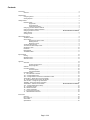
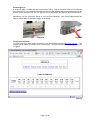
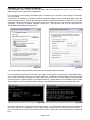
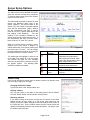
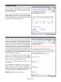
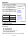
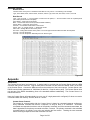
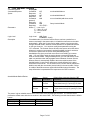
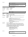
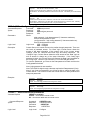
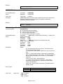
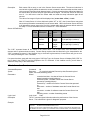
3890 Oakwood Ave.
Youngstown, OH 44515-3033
Phone: (800) 239-1226
Fax: (877) 517-2586
Commercial: www.SenSourceInc.com
Industrial: www.SenSource.biz
PCW-CSRX9 Counter Server Installation Guide & User’s Manual
Version 1.1
12/08/2005
Copyright © 2003, SenSource, Inc.
3890 Oakwood Ave.
Youngstown, OH 44515
PH: 800-239-1226
FX: 877-517-2586
Email: [email protected]
Contents
Introduction
2
Overview.........................................................................................................................................................2
Requirements
2
Configuring Server .........................................................................................................................................2
Viewing Reports .............................................................................................................................................2
Getting Started
2
Hardware Setup..............................................................................................................................................2
Apply Power ...................................................................................................................................2
Connecting to PC ...........................................................................................................................3
Testing the Connection ..................................................................................................................3
Changing your PC's default IP Address .........................................................................................................4
Change the Server's default IP Address ........................................................................................................5
Changing the Server's name ..........................................................................Error! Bookmark not defined.
Adding Sensors ..............................................................................................................................................6
Viewing Counts...............................................................................................................................................7
Server Setup Options
8
The Status Screen..........................................................................................................................................8
Sensor Setup..................................................................................................................................................8
Changing the sensor's name..........................................................................................................8
Deleting a sensor ...........................................................................................................................8
Replacing a sensor ........................................................................................................................8
The Server Setup Screen ...............................................................................................................................9
The Communications Setup Screen...............................................................................................................9
Set Server's Clock ........................................................................................................................................10
Passwords ....................................................................................................................................................10
Reset Options...............................................................................................................................................11
The Reset Enabler .......................................................................................................................................11
Export Options
12
Viewing .........................................................................................................................................................12
Standard Format...........................................................................................................................................12
Alternate Format...........................................................................................................................................14
Appendix
14
Serial Port.....................................................................................................................................................14
Counter Server Protocol...............................................................................................................14
CRC16 Algorithm .........................................................................................................................15
Software .......................................................................................................................................................15
Command Overview .....................................................................................................................................16
Command Syntax.........................................................................................................................16
Time representations ...................................................................................................................16
Command Outline.........................................................................................................................................16
‘A’ - Auto Add Mode command....................................................................................................................17
‘CC’ – Configure/Read Clock .......................................................................................................................18
‘CD’ – Configure/Read Counter Server Identification Label .........................................................................18
‘CFACTORY’ – Reset Server to factory defaults..........................................................................................19
‘CI’- Configure/Read Counter Server IP Address .........................................................................................19
‘CPD’ & ‘CPC’ – Configure Login Passwords...............................................................................................20
‘CRESET’ – Reset some server information ................................................................................................20
‘CRESTORE’ – Restore Server defaults ........................................................Error! Bookmark not defined.
‘CS’ - Configure/Read Sensor Setup...........................................................................................................21
‘IC’ – Information Counts ..............................................................................................................................22
‘IM’ – Media Information ...............................................................................................................................23
‘IV’ – Version Information .............................................................................................................................23
‘L’ – Login/Logout Commands......................................................................................................................23
‘S’ - Get Status Data Command ..................................................................................................................24
Error Codes
24
Overview.......................................................................................................................................................24
Error Code List .............................................................................................................................................24
Serial Cable ..................................................................................................................................................25
Specifications ...............................................................................................................................................25
Page i of 26
Introduction
Overview
The Counter Server is designed to collect data from wireless counter sensors and display that data through an
HTML page that can be viewed with an ordinary browser. The server consists of three parts, the server, a
receiver to receive the data from the sensors, and the user's computer, which configures the server and views the
data.
The Counter Server gives reports of counts by half hour, hour, day, week and month. The Counter Server also
makes this same data available as text files downloadable through the browser using FTP.
The Counter Server can manage up to 16 sensors. It can hold data for those 16 sensors for 3 months at 30 minute intervals,
and for 1.5 years at day intervals.
Requirements
Configuring Server
•
•
•
The Counter Server, both the receiver and the server itself plus at least one counter sensor.
A computer with an ethernet card for TCP/IP communications
Web browser, such as Internet Explorer
Viewing Reports
•
•
A web browser such as Internet Explorer
Access via network to the Counter Server
Getting Started
Hardware Setup
Antenna
Ethernet Port
Power Light
(RED)
Receiver Connector
Ethernet Activity
Light (GREEN)
Power Connection
Local Serial Port
Figure 1
Apply Power
Plug the power supply into the Counter Server and make sure it is connected to a working outlet. The red
power light will come on when the Server is plugged in.
The red light indicates that the Counter Server is functioning. The Counter Server also uses the red lights
to indicate reception of a packet from a transmitter. The Counter Server’s red light will blink momentarily
indicating a packet has been received and processed.
Page 2 of 26
Connecting to PC
A crossover cable is included with the Counter Server setup. Plug the crossover cable into the Ethernet
port on the back of your computer (see figure 2a) and plug the opposite end into the Ethernet port on the
Counter Server (see figure 2b). The ‘Lnk’ light will turn on indicating a valid Ethernet physical connection.
Alternatively you can connect the Server to your Local Area Network. Your network administrator can
help you decide which IP Address to assign to the server.
Figure 2a
Figure 2b
Testing the Connection
To check to see if you have made a connection, open your browser and type in http://192.168.1.55 . The
browser should display the Counter Server count screen. The screen will not show sensors until they are
configured.
Figure 3
Page 3 of 26
Changing your PC’s default IP Address
If you have been unable to see the Server's web page, when connecting directly to your PC, you may need to
make changes to your computer's IP configuration.
First, connect the Server directly to the Ethernet port on the back of your computer. Next, change the IP settings
on your computer.
To change the IP settings on a computer running the Windows operating system, follow these steps: select the
following ‘Control Panel Æ Network and Internet Connections Æ Network Connections’; right-click on your LAN
connection and select Properties (see figure 4a); select the TCP/IP service for your network card and choose
‘Properties’. Specify an IP Address’ (example: 192.168.1.40 255.255.255.0); and fill in the initial values for
Subnet Mask and IP Address (see figure 4b).
Figure 4b
Figure 4a
It is recommended to restart Windows at this time to ensure changes have been made.
From a command prompt found from the start menu, (Start Æ All Programs Æ Accessories Æ Command Prompt),
verify TCP/IP changes by running the command IPCONFIG. IP Address and Subnet Mask should match what
you’ve previously entered (see figure 5a). Next, check communication to the Counter Server by using the PING
command from the command prompt. Type PING followed by a space and then the IP Address of the Counter
Server (default: 192.168.1.55) then wait for a response. A successful PING will receive a reply (see figure 5b).
Figure 5a
Figure 5b
At this time refer back to ‘Testing the Communication’ section. You should now be able to type the IP Address of
the Counter Server into the address line of your Internet Browser and view your Counter Server (see figure 3). If
you are still not able to communicate with the Counter Server, contact your network administrator for additional
help.
Page 4 of 26
Change the Server's default IP Address
In order for the Counter Server to communicate TCP/IP, it needs an IP Address, Subnet Mask, and possibly a
Gateway Address. If you are connecting the Counter Server to your LAN, you should change the Counter
Server’s default settings (IP Address: 192.168.1.55; Subnet Mask: 255.255.255.0; Gateway: blank; DNS
Server: blank).
To change the IP Address and Subnet Mask for the Counter Server go to the "Setup" link and then click on
"Communications". There you can enter a new IP Address and Subnet Mask for the Counter Server.
Before you change the IP Address you should
PING the new IP Address to make sure that
no computers or devices on your network
have the IP Address already. Type PING
followed by a space and then the new IP
Address then wait for a response. If the result
of the PING is "Request timed out" (see figure
6) then there is no other devices on that IP
Address and you can safely change the IP
Address of the Counter Server.
Figure 6
Once you know the IP Address you want,
enter it into the "IP Address" box on the
Communications Setup screen (see figure 7).
Enter the Subnet Mask also. You may need
to ask your network administrator for a Subnet
Mask. When you are ready, click the "Submit"
button at the bottom of the page. The
program will attempt to change the IP
Address of the Counter Server. If successful,
the browser will redirect to the new IP
Address and at the bottom of the screen, in
green letters, it will say, "Submission
accepted. Parameters updated!" Click on the
link "Setup Menu" at the bottom of the page to
return to the Setup menu
You may need to reset your PC back to its
original IP Address settings at this time if you
had
previously
changed
them.
Communication with the Counter Server’s
new IP address may not be possible until this
is completed.
Figure 7
Page 5 of 26
Changing the Server's name
Click on the "Server" link of the setup menu.
From this page you can enter a name for the
Counter Server. You can set the maximum
amount of time that may pass between sensor
transmissions before the sensor is declared
offline. You may set the "Auto Add" mode for
the Server.
The default "Auto Add" mode is "Service
Mode".
"Service mode" means the Server
will only add sensors to its list if it receives a
sensor packet that has been sent by pressing
the service button on the transmitter. "All"
means that the Server will add a new sensor
any time it receives a transmission from a
sensor that is not already in its list.
"Off"
means that the Server will never add new
sensors to its sensor table.
Figure 8
Adding Sensors
The next thing you need to do is set up the sensors that the
Counter Server will monitor.
The Server by default adds sensors to its configuration list when
it receives a packet that has been transmitted in Service Mode.
You can send a transmission in Online Mode by pressing the
service mode button on the sensor (see figure 9 or reference
sensor manuals) for less than 1 second.
The Counter Server will add them to its configuration and you
may view their data from the main HTML screen.
You may
need to refresh the screen a couple of times before the counter
shows up.
Page 6 of 26
Figure 9
Viewing Counts
To view the current sensors and their data, start your Internet Browser and enter the Count Server's IP Address in
the "Address:" line.
Figure 10
The user can view the count total at different time granularities. The user can view counts summed per Half Hour,
per Hour, per Day, per Week, or Per Month. Clicking on the links at the top of the screen will change the time
granularity. The user can also navigate through count history by using the "Prev" and "Next" buttons at the
bottom of the screen. Clicking the "Now" button will take you to the current date and time. If counts have been
recorded for the current view, they will be displayed. Otherwise (for example, if the requested view is in the future
or a time earlier than the first sensor transmission) the cell for that time period will display "n.a." (not applicable).
Each configured sensor has a row in the table. Direction counters show counts on two lines for Count A and
Count B. The total of all counts for all sensors for that time period will be displayed on the bottom row of the
table.
For all time intervals greater than Half Hour, the top row of the table contains links to focus in on a smaller time
interval. For example from the "Per Month" view you can click on a specific month, like January, in order to see
the weekly breakdown of counts for January.
To get the latest data, click the "Now" button or click the "Refresh" button on the browser.
The date and time on the display show the time the report was generated.
You can make the table appear smaller if you want it to fit on the screen better by (in Internet Explorer) going to
View | Text Size | Smaller.
Page 7 of 26
Server Setup Options
The Status Screen
The status screen shows detailed information
about the sensors currently being monitored.
To view the status screen click on the "Status"
link from the main screen.
The status table (see table 1) shows, for each
sensor, the identifying label name of the
sensor ("Sensor") , the serial number of the
sensor ("ID"), the number of seconds elapsed
since the last transmission ("Age"), whether
the last transmission was sent in service
mode or not ("Srv"), and the data value of the
last reading ("Last Reading").
The last
reading is the cumulative recorded on the
sensor since startup or since the last reset. If
the transmission was sent in service mode,
there will be an "X" in the "Srv" column.
When the Counter Server receives a transmission from a new sensor it assigns it a
default label which is the sensor position plus
the sensor type ("1Count"). You can change
the label assigned to the sensor by clicking on
the label name in the "Sensor" column.
The status table will highlight in yellow a row
in the table if the sensor is in an error state.
The browser will show an error message
when the mouse pointer is moved over top of
the graphic symbol.
The following table
shows the possible error states:
Figure 11
Symbol
Error
Message
Offline
Beam blocked
Check Battery
No Line
Power
Description
The Server hasn't received a
transmission from this sensor
within the timeout interval, which
is set in the "Server Setup" screen
under "Sensor Offline Time".
the sensor beam seems to be
blocked by some obstruction.
The battery voltage is low or the
battery is not present
Line power has been removed or
is too low.
Table 1
Sensor Setup
Here you can change the sensor name or replace a sensor. Hit "Submit" when
you are ready to apply your changes.
Changing the Sensor's Name
Type a new name in the "Sensor Name" box.
Deleting a Sensor
The very last sensor in the table on the status screen can be deleted.
Click the "Delete Sensor" box and hit the "Submit" button.
Replacing a Sensor
If you want to swap out a sensor but keep the new sensor in the same
position as the old one, simply go to the sensor setup screen for the
sensor you want to replace and type in the new sensor's serial number in
the "Serial No." box. Hit the "Submit" button and the Counter Server will
update its configuration with the new sensor information. As always, enter
the serial number with care!
Figure 12
Page 8 of 26
The Server Setup Screen
The setup screen allows you to set some parameters for the
Counter Server. You can change the name of the Counter Server.
Note: the Server Name is also used as the Login User Name
when passwords have been set up.
"Sensor Offline Time" allows you can set the amount of time that
can elapse between transmissions from one sensor before the
sensor is declared offline.
You can set the "Auto Add" mode on the server. The "Auto Add"
mode tells the server what to do when it receives a transmission
from a sensor that is not already in the server's sensor table. If
"Auto Add" is "Off" then the Server will ignore all transmissions
from sensors that are not in the table already. If "Auto Add" is
"All", the Server will add a new sensor to the sensor table each
time it receives a transmission from a new sensor. If "Auto Add" is
"Service Mode" then the Server will only add a new sensor to the
table if the transmission is received in service mode.
When you are ready to make changes, press the "Submit" button.
Click the "Home" link to see the table of counts and click the
"Setup Menu" to go back to the setup menu.
Figure 13
The Communications Setup Screen
The communications setup screen allows you to
change the Counter Server's IP Address, Subnet
Mask, and Gateway. Enter these parameters as
necessary and click "Submit". The new parameters
are sent to the Counter Server and an intermediate
screen displays.
If the IP Address is changed successfully, the
browser will redirect itself to the new IP Address
and there will be a message on the screen saying,
"Submission accepted! Parameters updated."
If the change of IP Address was not successful,
you will see a browser error page telling you that
the file cannot be found.
If you check the box that says, "Revert back to
previous settings if no connection in 5 minutes"
then the program will try to update the Server's IP
Address. If it cannot make a connection within 5
minutes thereafter, it will reset the IP Address to
the previous settings.
If the Counter Server will receive data from Sensor
Repeaters, you need to set the radio channel.
Page 9 of 26
Figure 14
Set Server's Clock
You will need to make sure the server's clock is set
correctly so that it can display the counts and totals
correctly. Choose "Set Clock" from the Setup menu,
enter the correct values, and click "Submit" to set the
Counter Server's clock.
If you set the clock back more than 30 minutes the
Counter Server will require you to reset the counts
before updating the clock. If you set the clock ahead
more than 30 minutes the Server will pad the log with
zeroes (0) for the counts for those times.
Figure 15
Passwords
Counter Server controls access to the different
resources of the Counter Server through passwords.
There are two levels of Login access for the Counter
Server: Data and Config. Through the Data Login, the
Counter Server allows access to the data portions of the
Counter Server like the HTML file, current readings,
Historical and Event Logs, and setup information.
Through the Config Login, the user can make changes
to the Counter Server setup. With the Config Login, the
user has all the rights of the Data Login as well . If the
Login password has been configured and the user has
not logged in yet, the Counter Server will respond with
an error message to commands.
If you set up a password to restrict viewing ("Report
Password") then changing the setup will be restricted
also. If you set up a password for setup ("Setup
Password") then viewing is not also restricted.
Click "Submit" to establish password protection in the
Counter Server.
After passwords are established, you will encounter a
screen requesting a password when attempting to
perform an action that is password protected. The
screen will ask for a user name; this is the name of the
Counter Server. Enter your password and hit "OK".
WARNING: Passwords are case sensitive.
Figure 16
Page 10 of 26
Reset Options
Be careful when you reset values. There is no way to undo
these changes.
On the reset screen you may select to reset the sensor counts to
zero ("Reset Counts"), delete all the sensors from Counter
Server's setup table ("Delete All Sensors")* or reset the People
Counter Server to factory settings ("Reset People Counter
Server").
Resetting the Counter Server to factory settings will reset the IP
Address back to the default 192.168.1.55. The browser will not
redirect itself and you will need to re-enter the IP Address into
the "Address" bar.
* Note: To delete non-active sensors, you must enter the Sensor
Setup menu and select the non-active sensor. Check the “Delete
Sensor” box and click on “Submit.”
Figure 17
The Reset Enabler
The Reset Enabler allows you to reset and clear all the Counter Server settings in case you become unable to
communicate with the server through the browser. Use the Reset Enabler with care, as it will erase the
configuration and all data!
To use the Reset Enabler plug it into the serial port on the back of the Counter Server. Power down the Counter
Server for 30 seconds or more and then power up. When the Counter Server detects the Reset Enabler it will
blink the power light at the rate of twice per second. If the Reset Enabler is removed within one minute, the
Counter Server will reset itself back to the factory defaults. If the Reset Enabler is left on for longer than a minute,
the Counter Server will ignore it.
Page 11 of 26
Export Options
Viewing
From the main screen click on the "Export" link. You will be brought
to the reports section. From here you can view and save data in text
format. You may also right-click with your mouse on the link. A
menu will pop up. If you choose "Save Target As…" you can use the
resulting Save dialog box to save the counts report to a text file on
your computer. You can view these files with any text editor.
You also view a directory of the available files using the Server’s IP
Address in the URL: ftp://192.168.1.55
There are two file formats. The Standard Format is more compact
and provides counts for all sensors for period on each line. The
Alternate Format provides a count per line, per sensor, per period.
The files have a title based on the time span of the report plus a
timestamp. An example title is this: "CNT24-012003103434.txt"
This is the count file for the last 24 hours and the report was
generated on 01/20/03 at 10:34:34 a.m.
The following is a table of the available files:
Web page title
Standard Format
Counts for the last 24 hours
Counts for the last 7 days
Counts for the last 31 days
All Counts for the day Log
Alternate Format
Counts for the last 24 hours
Counts for the last 7 days
Counts for the last 31 days
All Counts for the day Log
File name
CNT24-timestamp.txt
CNT7DAYS-timestamp.txt
CNT31DAYS-timestamp.txt
CNTPERALL-timestamp.txt
REC24-timestamp.txt
REC7DAYS-timestamp.txt
REC31DAYS-timestamp.txt
RECPERALL-timestamp.txt
Figure 18
If the server has been password protected at the report level need to
login through the ftp client. The user name is the name of the Server
and the password is the report level password.
Standard Format
There are eight different record types. Each record starts with a number that tells what kind of record it is.
Server Counter Information
0, date, time, server name, mac, number of sensors, setup timestamp, report start, report finish
Where:
date – date that the report was generated.
time – time that the report was generated.
server name – name of the counter server.
mac – MAC address of the server.
number of sensors – the number of sensors currently being monitored.
setup timestamp – the time stamp of the last setup change.
report start – the time and date of when the report starts.
report finish – the time and date of when the report finishes.
Sample record: 0,01/20/03,14:36:02,Sample PC,00:90:C2:C1:0F:D9,2,01/20/03 13:10:17,01/17/03 00:00:00,01/20/03
14:36:01
Page 12 of 26
Sensor Names
1, date, time, sensor name1…sensor namen
date – date that the report was generated.
time – time that the report was generated.
sensor name – name of the sensor
n – number of sensors
Sample record: 1,01/20/03,14:36:02,Main,Warehouse1
Sensor Serial Numbers
2, date, time, serial number1…serial numbern
date – date that the report was generated.
time – time that the report was generated.
serial number – serial number of the sensor
n – number of sensors
Sample record: 2,01/20/03,14:36:02,0000000000608220,000000001C110321
Sensor Types
*3, date, time, sensor type1 …sensor typen
date – date that the report was generated.
time – time that the report was generated.
sensor type – type of sensor: 1 – people counter; 2 – directional counter
n – number of sensors
Sensor Period A Counts
7, date, time, countA1 …countAn
date – date of the period.
time – time of the period.
countA – count for the period for the first set of counts for the sensor. The period is either 30 minutes or 1 day
n – number of sensors
Sample record: 7,01/17/03,00:00:00,127,115
Sensor Current Interval A Counts
8, date, time, countA1 …countAn
date – date of the current interval.. This is a partial total for the interval, as the current interval has not been completed yet.
time – time of the current interval.. This is a partial total for the interval, as the current interval has not been completed yet.
countA – count for the current interval for the first set of counts for the sensor.
n – number of sensors
Sample record: 8,01/20/03,00:00:00,176,147,142,1,3,353
Sensor Period B Counts
*9, date, time, countB1 …countBn
date – date of the period.
time – time of the period.
countB – count for the period for the second set of counts for the sensor.. The period is either 30 minutes or 1 day
n – number of sensors
Sensor Current Interval B Counts
*10, date, time, countB1 …countBn
date – date of the current interval.. This is a partial total for the interval, as the current interval has not been completed yet.
time – time of the current interval.. This is a partial total for the interval, as the current interval has not been completed yet.
countB – count for the current interval for the second set of counts for the sensor.
n – number of sensors
* These records are only included if a Directional Counter is in the sensor list.
Figure 19
Page 13 of 26
Alternate Format
Header Record
The first record of every file is a header that has titles for every column. The following is an example:
Type, Server Name, MAC, Sensor Name, Serial No, Sensor Type, Start Time, End Time, Count A, Count B
Data Record
Type – type of record: 1 – record contains counts for the full period; 5 – record contains counts for a partial period
(the current period which is incomplete).
Sever Name – name given to the Server
MAC – serial number of the Server (the Ethernet MAC address)
Sensor Name – name given to the sensor
Serial No – 16 character serial number of the sensor
Sensor Type – 0 – people counter; 1 – directional counter
Start Time – starting date and time of the period
End Time – ending date and time of the period. For record type 5 this time will be less than the full period.
Count A – count for the period
Count B – count for the period. Will always be 0 for Sensor Type 1.
Figure 20
Appendix
Serial Port
The Counter Server has a local serial port. A special cable is provided with the Counter Server that has a DB9
connector and a phono connector. Plug the male phono connector into the connector labeled “serial” on the front
of the Counter Server. Connect the DB9 connector to the serial port of the host computer. Counter Server uses
RS232 communication parameters of 19200 baud, 8 data bits, 1 stop bit and no parity. The Counter Server does
not use any of the RS232 handshaking lines or the standard software handshaking. The Counter Server is a
RS232 DCE device.
Note: the Counter Server will automatically log out a user (if a login password is configured) if it does not receive
a command within the Inactivity Timeout, which is 1 minute.
Counter Server Protocol
The system for communicating with the Counter Server is based on command-response architecture.
Every submitted command will receive a response, as long as there is a connection. Successful
commands are responded to with an echo of the primary command, and if the command returns data, the
data is appended to the primary command echo after a comma. The primary command is the submitted
command string in its entirely or up to but not including the first comma. Sending the next command
before receiving a response to the last command is an error.
Page 14 of 26
Each command must be prefixed with an ASCII 02 character (STX) (on most terminal emulation
programs, key in Ctrl-B) and must end with an ASCII 13 character (CR) (on most terminal emulation
programs, key in Ctrl-M or Enter). This protocol will work with all the Counter Server communication
media: local serial port, and TCP/IP.
Example
Command:
Response:
Remarks:
<STX>S<CR>
<STX>S,6,082701111800,na,na<CR>
<STX> is an ASCII 02 (or Ctrl-B on the keyboard)
*<CR> is an ASCII 13 (Ctrl-M or Enter on the keyboard)
There is an additional layer of communications protocol that is media-specific. This has been added to
ensure reliability when using media lacking built-in error detection. This protocol is recommended to be
used with the Counter Server’s local serial port. The command must be prefixed with an ASCII 01
character (SOT) (on most terminal emulation programs, key in Ctrl-A), then following the command with a
4-character ASCII hex CRC16. The command is then terminated with an ASCII 13 character (CR) (on
most terminal emulation programs, key in Ctrl-M or Enter). The CRC16 must be calculated using the full
command but does not include the ASCII 01 (SOT) or the ASCII 13 (CR). An ASCII 01 (SOT) prefixed
command not followed by a CRC16 will result in an error. Counter Server will respond with a response
prefixed with an ASCII (SOT), followed by a 4-character ASCII hexadecimal CRC16 and terminated with
the ASCII 13 (CR). The returned CRC16 is calculated using the full response but does not include the
ASCII 01 (SOT) or the ASCII 13 (CR).
Note: The letters of the 4-character ASCII hexadecimal CRC16 must be in uppercase.
Example
Command:
Response:
Remarks:
<SOT>S3D40<CR>
<SOT>S,6,082701111800,na,na3A3E<CR>
<SOT> is an ASCII 01 (or Ctrl-A on the keyboard);
“3D40” is the calculated CRC16 value in 4-character ASCII hexadecimal of the command “S”; “3A3E” is the
calculated CRC16 value in 4-character ASCII hexadecimal of the response “S,6,082701111800,na,na”.
CRC16 Algorithm
The CRC16 Algorithm is a sophisticated method of checking the integrity of transmitted data for transmission errors.
The algorithm indicates whether or not the data has any error. It does not indicate which bit or how the error
occurred. Counter Server ignores data packets that have errors. The host should resend the command if the
response from the Counter Server has errors.
Software
The interface to the Counter Server was designed to meet common standards and be easy to use. You can use
common software that either comes with your operating system or can be purchased to diagnose common
problems and to communicate with the Counter Server. You can use a communication program that has terminal
emulation to get familiar with the Counter Server commands and communications. Once you are familiar with the
commands, you can automate the communications using common development programming languages.
Here are some examples of common software commands:
Microsoft Windows
PING – command to test the TCP/IP connection.
WINIPCFG – utility that shows the computer’s IP Address.
IPCONFIG – utility that shows the computer’s IP Address (DOS program).
Telnet – command to see responses via TCP/IP. Note: Counter Server uses port 1000 as default.
HyperTerminal – provides terminal emulation program to communicate via TCP/IP, and serial port.
Note: HyperTerminal can answer calls via TCP/IP but does not work very well with the Counter Server in
this mode because HyperTerminal echos characters it receives.
Note: The easiest way to configure a sensor is to read the default information and then copy that string to a text
editor, edit it, and copy it back to the communications program. Remember to remove the parameter specifying
type. When configuring the sensor you do not specify the type. The Counter Server will determine the type when
it receives a data packet from the sensor. Therefore, until the Counter Server receives that first packet, it will
classify the type as ‘0’, Unknown.
Page 15 of 26
Command Overview
Command Syntax
The following table describes the shorthand used to define each command.
Syntax Element
Purpose
<>
Enclose a set of options, ones of which is required
|
Separates elements in a set of options
[]
Enclose an optional expression
…
Denotes variable length
Marks repeatable expression
1 ,…x
n
Only or low row number of a sensor
m
High row number of a sensor
Strings in italics are place holders for values
Italics
Rules governing commands include:
• Command strings may contain no spaces.
• Reserved characters: commas (,), pipes ( | ), SOT (ASCII 1), STX (ASCII 2), carriage
returns (ASCII 10), and the bell code (ASCII 7) are reserved, and may only appear as part
of the command syntax. Do not use these characters in label names or state names.
• Command strings have a maximum length of 128 characters.
• When specifying a range, the max is ten sensors. Specifying a range with more than ten
will return an error.
Time representations
Date and Time Stamps
Time and date stamps or times that are set or compared to
the real-time clock are always expressed in military time
and represented as: mmddyyhhnnss
Where
mm – month of the year
dd – day of the month
yy – year starting at year 2000
hh – hours
nn - minutes
ss - seconds
Interval or Duration Times
Times that are duration are always expressed in
military time and represented as:
hhnnss or
ddhhnnss
Where
dd – number of days
hh – number of hours
nn – number of minutes
ss – number of seconds
Command Outline
Command
A<T|F|R|S>
CC<S[F]|R>
CD<S|R>
CFACTORY
CI<S|R>
CP<D|C>
CS<S|R|C[F]>[n]
L<I|O>
IC
IM
IV
CRESET<counts|all>
S
CRESTORE
Description
Options & Parameters
Auto Add Mode
<True|False|Read|Service>
Configure/Read Clock
<Set[Force]|Read>(mmddyyhhnnss)
Configure/Read Counter Server Identification
<Set|Read>(ID Name)
Clear the entire configuration of the Server and reset everything to factory defaults.
Configure/Read Counter Server IP Address
<Set|Read> (IP Address, Subnet [,
Gateway][, Name Server][,Port])
Configure Login Passwords
<Data|Config> (password)
Configure/Read/Clear Sensor Setup
<Set|Read|Clear[Force]> (sensor
Analog: (AScale,Offset,Units,Decimal_Places) index, serialno, label(I/O point
Integer: (IScale,Offset,Units,Decimal_Places)
setup(s)))
Data: (D<Y|N>)
State: (SName1[,…Namex]), sensor
type
Login/Logout
<In|Out> (password)
Information Counts
Media Information
Version Information
Resets all sensor counts to zero | Resets counts to zero and clears sensor table
Get Status Data
Clears all sensors, counts, and all other parameters except Communication
information such as IP Address.
Page 16 of 26
‘A’ - Auto Add Mode command
Command Options
Command/Response
Syntax
Parameters
A<T|F|S|R>
Command:
AT
Response:
AT
Command
AF
Response:
AF
Command:
AS
pressed)
Response:
AS
Command:
AR
Response:
AR,<T|S|F>
Where: ‘T’ – true or yes
‘F’ – false, no or off
‘S’ – service mode
‘R’ - read
turn AutoAdd Mode on
turn AutoAdd Mode off
turn on AutoAdd (add when service
Query AutoAdd Mode
Login Level:
AR – Data
AT,AF,AS – Config
If AutoAdd mode is on and the Counter Server receives a packet from a
sensor not already in the sensor table, it will add the new sensor to the table
automatically. When the Counter Server adds a sensor to the sensor table
through AutoAdd mode it assumes certain defaults for the parameters based
on the type of sensor. You can then modify these parameters using the
“CS” command. The Counter Server will add a new sensor to its table either
whenever it receives a new sensor’s packet [AutoAdd] or when it receives a
new sensor’s packet sent in service mode [AutoAdd(service)].
AutoAdd(service) gives you a little more control over building your sensor
table. You may need to push the service button to transmit the data and
have the sensor added. Using AutoAdd(service) you can add sensors to the
table in a particular order and segregate sensors between Counter Servers.
When a sensor is automatically added to the sensor table because of the
AutoAdd mode, Counter Server will assume certain defaults for the setup
information for the sensor. For the sensor name, Counter Server prefixes the
default name with the row number (sensor index) in the sensor table. Below
is a table of the different sensor types with the default setup information. The
setup information is expressed as the response to the CSR command.
Login Level
Description
AutoAdd Mode Default Entries
Sensor
Model
IR Counter
Sensor
Description
People
Counter
Directional
Counter
Directional
Counter
Default Setup (response from the CSR
command)
6,000000000013D6F1,15Count(S4,trans.,
open,closed,error)(I1,0,open,0)(I1,0,close,
0)
18,000000000013D6F1,1DirectCnt(S4,tran
s.,open,closed,error)(I1,0,open,0)(I1,0,clos
e,0)
The sensor is given a default name, which is the name of the physical type of sensor. The Counter Server
prefixes the default name with the row number in the sensor table. The following is a table that shows the default
names:
Sensor Model
IR Counter
Direct CNT
Sensor Description
People Counter
Directional Counter
Default Sensor Name
“Count”
“DirectCnt”
Page 17 of 26
‘CC’ – Configure/Read Clock
Command Options
Command/Response
Syntax
Parameters
Login Level
Description
CC<S[F]|R>
F – clear the Historical and Event Logs and set the Counter Server clock
S – set the Counter Server clock
R – read the current clock setting
Command:
CCSmmddyyhhnnss
Response:
CCSmmddyyhhnnss
Command:
CCSFmmddyyhhnnss
Response:
CCSFmmddyyhhnnss
Command:
CCR
Response:
CCR,mmddyyhhnnss
Where:
mmddyyhhnnss – date and time to set the clock or the date
and time of the read clock
Login Level:
CCS – Configure
CCR – Data
The “CC” command configures or reads the Counter Server time of day
clock. The Counter Server uses the clock for the Historical Log, Event Log,
Event Alarms, and Periodic Timer Callout. Setting the correct time for the
Counter Server is crucial for Counter Server operations that concern time.
The Counter Server will return an error 16 for the “CCS” command when
there are records in the Historical Log or the Event Log. The Historical and
Event Logs must be empty before the clock can be set unless the “F” option
is used.
The Counter Server’s clock is set at the factory to Eastern Standard Time.
The Counter Server’s clock will drift over time. The realtime clock should be
set periodically.
Note: The Counter Server’s clock and internal time registers will rollover in
the year 2048.
Examples
Command:
CCS082901224100
Response:
CCS082901224100
Remarks: set the clock to 08/29/01 22:41:00
Command:
CCR
Response:
CCR,082901224212
Remarks: the Counter Server’s clock is set to 08/29/01 22:42:12
‘CD’ – Configure/Read Counter Server Identification Label
Command Options
Command/Response
Syntax
Parameters
Login Level
Description
CD<S|R>
S – set the Counter Server Identification Label
R – read the Counter Server Identification Label
Command:
CDSlabel
Response:
CDSlabel
Command:
CDR
Response:
CDR,MAC,label
Where:
label –label name used to identify the Counter Server.
(maximum 19 characters)
MAC – Counter Server’s Ethernet MAC address
Login Level:
CDS – Configure
CDR - None
The Counter Server Identification Label is to uniquely identify the Counter
Server. The Identification Label is displayed in the HTML File and used in
the subject line in sent emails. The MAC address is permanently part of the
Counter Server cannot be changed and is unique for all Ethernet interfaces.
Page 18 of 26
Examples
Command:
Response:
CDSmy Counter Server
CDSmy Counter Server
Command:
CDR
Response:
CDR,00:90:C2:C0:15:D9,my Counter Server
Remarks: “00:90:C2:C0:15:D9” is the Counter Server’s MAC. “my Counter Server” is the
identification label for the Counter Server.
‘CFACTORY’ – Reset Server to factory defaults
Command/Res
ponse Syntax
Command:
Response:
CFACTORY
CFACTORY
Login Level
Login Level:
Configure
Example
Command:
Response:
CFACTORY
CFACTORY
‘CI’- Configure/Read Counter Server IP Address
Command
Options
Command/Res
ponse Syntax
Parameters
Login Level
Description
CI<S|R>
S – set the Counter Server IP Address
R – read the Counter Server IP Address
Command:
CISIP Address, Subnet Mask[, Gateway address][,name server] [,port]
Response:
CIS
Command:
CIR
Response:
CIR, S, IP Address, Subnet Mask[, Gateway address][,name server]
Where:
S – static entry.
IP Address – IP Address formatted as xxx.xxx.xxx.xxx
Subnet Mask – Subnet Mask formatted as yyy.yyy.yyy.yyy
Gateway address – Gateway address formatted as zzz.zzz.zzz.zzz. (required
for email support)
name server – IP Address of the name server formatted as vvv.vvv.vvv.vvv.
(required for email support)
port – IP port number (optional) (default is 1000)
Login Level:
CIS – Configure
CIR - Data
In order to use the Counter Server Ethernet interface, the Counter Server must be
assigned an IP Address and a Subnet Mask. The Gateway address is optional (if not
using email). The name server and Gateway are required when using email. Consult
your network administrator for more information. The Counter Server will process the
“CI” command through the communication media. The Counter Server will disconnect
the current TCP/IP session while changing the IP Address.
Note: dynamic assignment of the IP Address is not supported.
The default IP Address is 192.168.1.55
The default Subnet Mask is 255.255.255.0
The default Gateway address is “” (null)
The default name server address is “” (null)
The default port is 1000
Examples
Command:
CIS192.168.1.46,255.255.255.0
Response:
CIS192.168.1.46
Remarks: set IP Address to “192.168.1.46” and the Subnet Mask to”255.255.255.0”. No Gateway
address and name server were set.
Page 19 of 26
Command:
CIR
Response:
CIR,192.168.1.46,255.255.255.0,,,1000
Remarks: the Counter Server’s IP Address is “192.168.1.46” and the Subnet Mask is
”255.255.255.0”. No Gateway address and name server were set. The default port of 1000 is being
used
Command:
CIS192.168.1.55,255.255.255.0,192.168.1.200,192.168.1.199,1300
Response:
CIS
Remarks: the Counter Server’s IP Address is “192.168.1.55” and the Subnet Mask is
”255.255.255.0”. Gateways is “192.168.1.200” and the name server is “192.168.1.199”. Gateway
and the name server are necessary for email. The port number is 1300.
‘CPD’ & ‘CPC’ – Configure Login Passwords
Command/Response
Syntax
Parameters
Login Level
Description
Command:
Response:
Command:
Response:
Where:
CPDdata password
CPD
CPCconfigure password
CPC
data password – login data password (7 characters maximum).
Enter a blank password to clear.
config password – login config password (7 characters maximum).
Enter a blank password to clear.
Login Level:
CPD – Configure
CPC – Configure
Counter Server can control access to the medias through passwords. There are
two levels of password access. For “Data” login, Counter Server allows the
access of the data information of the system such as the current sensor
readings, HTML file, Historical and Event Logs and setup information. For
“Configure” login, Counter Server allows the same access as the “Data” login as
well as access to change any of the setup information. If the Config login
password is blank, the Counter Server will assume the Data Login password for
the Config Login. Use the Login command “LI” to control and gain access.
To clear the passwords, you must set the Data password to blank and then the
Config password to blank.
Note: Login password is case sensitive.
Note: The HTML file login through a browser requires the Data password (if set).
Note: If you forget your password, you will not be able to collect the data in the
Counter Server. You will have to reset the Counter Server to factory defaults and
setup new passwords.
Examples
Command:
CPDadata
Response:
CPDadata
Remark: The “Data” login password was configured to “adata”.
Command:
CPCaconfig
Response:
CPCaconfig
Remark: The “Configure” login password was configured to “aconfig”.
‘CRESET’ – Reset some server information
Command Options
CRESET<counts|all>
Counts – set all sensor counts to zero
All – clear sensor table and set counts to zero
Command/Response
Syntax
Command:
Response:
Command:
Response:
CRESETCounts
CRESETCOUNTS
CRESETAll
CRESETALL
Login Level
Login Level:
Configure
Page 20 of 26
Example
Command:
Response:
CResetCounts
CResetCounts
‘CRESTORE’ – Restore Server Defaults
Command/Response
Syntax
Command:
Response:
CRESTORE
CRESTORE
Login Level
Description
Login Level:
Configure
CRESTORE deletes the sensor setup, sets all counts to zero, and restores
all factory defaults on the Counter Server except the commnication
information such as IP Address.
Example
Command:
Response:
CRESTORE
CRESTORE
‘CS’ - Configure/Read Sensor Setup
Command Options
Command/Response
Syntax
Parameters
CS<S|R|C[F]>[n]
S – set the sensor setup information
R – read the sensor setup information
C – clear the sensor setup table
F – force the sensor setup table to cleared
Command:
CSSn,serial no, label(sensor point setup)1…(sensor point
setup)x [,sensor type]
Response:
CSSn
Command:
CSRn
Response:
CSRn,sensor type,serial no,label(sensor point
setup)1…(sensor point setup)x
Command:
CSC
Response:
CSC
Command:
CSCF
Response:
CSCF
Where:
F – force the sensor table to be cleared. The Historical and
Event Logs will also be cleared.
n – sensor index. Each sensor is placed in a row in the sensor
table.
serial no – unique serial number of the sensor (16 characters)
label – identification label for the sensor. This label is displayed
with the sensor information in the HTML file. (16 characters
maximum)
sensor I/O point setup – described below
x – number of sensor points (5 maximum). This number
depends on the type of sensor. See the table below called
“Sensor I/O Definitions”.
sensor type – type of sensor enumerated. See table below for
possible values.
Sensor Types
Sensor type
6
18
Login Level
Login Level:
Description
People Counter
Directional Counter
CSS – Configure
CSR – Data
CSC - Configure
Page 21 of 26
Description
Each sensor fills an entry or row in the Counter Server sensor table. The sensor index then is
used to both originally define the where the sensor is located in the sensor table and then used to
retrieve sensor information (both data and setup). Once a sensor has been defined and placed in
the sensor table, the sensor I/O point type cannot be changed. The Counter Server will return an
error 6. You will have to clear the sensor table and send the setup information again for all
sensors.
The value of an Integer I/O point will be displayed as ( sensor data - offset ) * scale.
Note: If Counter Server is in Auto Add mode (either “AT” or “AS”), the Counter Server may place
sensor setup information automatically into the sensor table. When the Counter Server does this,
it will append the sensor setup to the end of the sensor table and it will assume default values for
the setup. For more information see the command “A” – Auto Add Mode.
Sensor I/O Definitions
Senso Type
No I/O Point
Example I/O Point Setup
r Type Description
.
Types
String
I/O
Pts
6
People
3
State,
(Strans.,open,closed,error)
Counter
Integer,
(I1,0,open,0)(I1,0,close,0)
Integer
18
Directional
3
State,
(Strans.,open,closed,error)
Counter
Integer,
(I1,0,open,0)(I1,0,close,0)
Integer
The “CSC” command clears all the entries in the sensor table. This includes both event information for all
sensors and I/O points and sensor setup. Counter Server requires that the Historical Log be cleared before the
“CSC” command is honored. If the Historical Log or the Event Log has entries, Counter Server will give an error
“16” when processing the “CSC” command.
If a sensor has been setup with the wrong type of I/O Point Type, the Counter Server will display “BAD CFG” for
the I/O data in the HTML File and the response to the “D” command. If this condition occurs, you will have to
delete the setup entry in the sensor table.
‘IC’ – Information Counts
Command/Response
Syntax
Parameters
Login Level
Description
Command:
IC
Response:
IC,commissioned date,Powered up date,Powered up,hard
resets, soft resets,watchdog resets
Where:
commissioned date – the date of when the Counter Server
started operations (mmddyyhhnnss)
Powered up date – the date of when the Counter Server
powered up (mmddyyhhnnss)
Powered up – number of times the Counter Server has powered
up
hard resets – number of hardware resets the Counter Server has
had
soft resets – number of software resets the Counter Server has
had
watchdog resets – number of watchdog resets
Login Level:
Data
The “IC” command gives information about the performance of the Counter
Server. This information is given for diagnostic purposes.
Example
Command:
IC
Response:
IC,090501130703,090601221649,4,3,0,0
Remarks: Counter Server commissioned data: 09/05/01 13:07:03; Counter Server last powered up
date: 09/06/01 22:16:49; 4 power ups; 3 hardware resets; 0 software resets; and 0 watchdog resets.
Page 22 of 26
‘IM’ – Media Information
Command/Response
Syntax
Parameters
Command:
Response:
Where:
IM
IM,name,login level,state,last activity,…
Login Level
name – name of the media
login level – current login level (none, data, configure)
state – message that describes the current state of the media.
The possible messages are the following: “Disabled”,
“Configuring”, “Waiting”, “Pushing”, “Connected”, and “Closing”.
last activity – duration of the last connection in seconds.
… - this information is repeated for every media. The media
information will be in the following order: Serial, TCP/IP.
Login Level:
Data
Example
Command:
Response:
IM
IM,Serial,T,N,686066612,TCP/IP,F,N,2333435
‘IV’ – Version Information
Parameters
Command:
Response:
notice
Where:
Login Level
version number – version number of the firmware of the Counter
Server
supported media list – list of the supported media for the Counter
Server delimited by |.
Server type – the type of server: Counter Server or Point Logger.
copyright notice – copyright notice for the Counter Server
software.
Login Level:
None
Command/Response
Syntax
IV
IV,version number,supported media list,server type,copyright
Example
Command:
Response:
IV
IV,1.1|Serial|TCP/IP,Counter Server,Copyright 2001 SenSource, Inc.
‘L’ – Login/Logout Commands
Command Options
Command/Response
Syntax
Parameters
L<I|O>
Command:
Response:
Command:
Response:
Where:
Login Level
password – either a data or configure password as setup with
the Configure Login Password (‘CPD’ and ‘CPC’). The password
parameter for this command is case sensitive.
level – level of access authorized by the Counter Server: 1 –
‘Data’; 2 – ‘Configure’
Login Level:
none
LIpassword
LIpassword,level
LO
LO
Page 23 of 26
Log in command
Log out command
Counter Server will allow access to a set of commands based on the entered
password. There are two levels of access ‘Data’ and ‘Configure’. With the
‘Data’ login, a user can access the current readings, the HTML file, Historical
and Event Logs and other information. With the ‘Data’ login, the Counter
Server will not allow access to commands that change the setup information.
With the ‘Configure’ login, the Counter Server will allow all commands to be
processed.
For the “LI” command, if the password does not match the Data or Config
password the Counter Server will return a 17 error code.
Note: Login is case sensitive.
Note: If you forget your password, you will not be able to collect the data in
the Counter Server. You will have to reset the Counter Server to factory
defaults and setup new passwords.
Description
Example
Command:
LInow
Response:
LInow,1
Remarks: Login using the password “now”. Logged in at level 1 which is the “Data” login level.
‘S’ - Get Status Data Command
Command Options
Command/Response
Syntax
Parameters
S
Command:
Response:
Where:
Login Level
Description
sensor count – number of sensors in the sensor list
last setup change time – time and date of the last setup change
(mmddyyhhnnss)
Login Level:
Data
Returns the number of sensors in the configuration table and the when the
last alarm from an event or periodic timer occurred.
The last setup change time can be used by host to determine if the setup has
been changed by a second host.
S
S,sensor count, last setup change time
Examples
Command:
S
Response:
S,3,101303090816,na,na
Remarks: 3 sensors configured in the sensor table. Last setup change occurred at 10/1/03 09:08:16.
Error Codes
Overview
When the Counter Server encounters a problem with the command string it will write out an error response. This
response takes the form <BEL>ee,Cmd where <BEL> is the ASCII 07 code (Ctrl-G on most terminal emulation
programs); ee is the specific error (see below); Cmd is an echo of the primary command that contained the error.
The primary command is the entire command string or the first part of the string up to but not including the first
comma.
Error Code List
Error Code
01
03
06
07
08
09
10
13
17
Meaning
Invalid command
Command syntax error; command cannot be parsed
Type cannot be changed or new sensor cannot be this type
Table is full
Invalid command configuration
No password – did not previously logged in
Not configured
Illegal parameter
Password given with the “LI” command does not match the Data or Config passwords
Page 24 of 26
Serial Cable
The following table shows the pin out of the Counter Server Serial Cable.
Counter Server
TX
RCV
GND
DB9 Female
2
3
5
1/8 Inch Phono Male
Tip
Body
Center Band
Specifications
Parameter
Power Supply Voltage
Power Supply Current
Receiver Frequency
Receiver Range with Sensor
Ethernet
Value
6 to 12 volts
250 milliamps
418 MHz
400 feet line of sight
10BaseT (10 MHz / 1.2 MHz effective rate)
Serial Port
Battery
19200 baud, no parity, 8 data bits, 1 stop bit
3.6 Volts TADIRAN TL-5101 1/2AA
Backup of the SRAM & real time clock: 6 years without power
3 months
1 year, 7 months
16
30 Minute Log
Day Log
Number of Sensors
Page 25 of 26