1
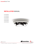
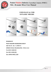
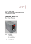
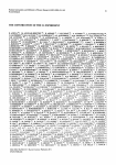
AR RCop ptix Variiable e Spiiral p plate e W With LC Drive D er U USE ER MA ANU UAL L Arc coptix SS.A Malladière 71 1C 200 00 Neuchâ âtel Swiitzerland Maiil: info@a arcoptix.co om Tel: ++41 32 731 04 66 Use er Manual V Variable Sp piral Plate ARC Coptix Swittzerland – www.arcop ptix.com Priinciple of the v variable e Spiral plate The e Spiral pllate (VSP) is a liqu uid crystall cell with h transparrent ITO elec ctrodes and a non--uniform aligned liquid crystal layer tthat gives s the elem ment its s special op ptical prop perties. A transverrse view in n Figure 1 give es an ove erview of the VSP structure. s Glass substrate LC Layer Tran nsparent elecctrodes V V~ Glass substrate Figu ure 1. Tra ansverse view of the VSP: L Liquid cry ystal layerr between n two glas ss substrrates with h transparent electrode. Op ptical axis s directorr can be ttilted with h the help p of an ap pplied bias s V. o transpa arent elec ctrodes it is possib ble to By applying a bias on the two tilt the liquid d crystal molecule es and at the same time th he opticall axis (an nd appare ent birefringence).. This me echanism permits to adaptt the reta ardance ((most cas ses tuned to Pi) off the varia able Spira al plate to o the wav velength of the ligh ht travers sing the element. e e VSP (als so caller Q-plate) has a top pological c charge off Q= 0,5. This The means that the form mula descrribing the e orientattion of th he optical axis (wh hen lookin ng at the e VSP from m the top) in pola ar coordin nates is g given by: Where q is tthe topolo ogical cha arge (0,5 in our ca ase) and a0 a constant offs set angle.. The topo ological charge c of the q–pla ate is 0.5 5. It is de efined at p production and can nnot be m modified. Figure 2 shows th he opticall axis disttribution for such a VSP. N Notice tha at on dem mand also o a topolo ogical cha arge 1 can n be produced. -1- Use er Manual V Variable Sp piral Plate ARC Coptix Swittzerland – www.arcop ptix.com Figu es showin ure 2.Line ng the lo ocal optica al axis (ffront view w) of a q q=0.5 VSP P. The e LG(0,1)) spiral mode m and the LG(0,1) radial pol. M Mode have e the sam me dough hnut shap ped inten nsity distribution but theirr electric field disttribution (polarization and phase) a are differrent. The e spiral p phase mode can be e written in cylindrrical coord dinates (rr,) as following (rref: G. Mac chavariani & al. ”Effect of the spiral phas se elementt on the ra adial-polarization (0,1 1)* LG beam m”,Opt. com mm. V.271)): decompos sed into two orthog gonal coh herent com mponents s as follow wing: or d Nottice that tthe null in ntensity in n the centter is due e to the ph hase sing gularity and the ph hase of th he beam is helical. Forr the radia al polariza ation mod de, the fie eld must be b defined d as vecto ors and d can be expressed e d as: Where Ex an nd Ey are e given ab bove and ex and ey are the e x and y unit vec ctors. -2- Use er Manual V Variable Sp piral Plate ARC Coptix Swittzerland – www.arcop ptix.com Diffferent working mode es: The ere are mainly thre ee types o of function ning modes with th he VSP: uthal outp put polariz zation 1) Radial or azimu 2 Spiral phase witth constant circula 2) ar output polarization 3 Neutra 3) al (no cha ange) The e output b beam of the VSP w will be defiined by tw wo param meters: 1) The input polarization lin near or cirrcular 2 The ph 2) hase retarrdation off the VSP. n the VSP P in Pi and d the inpu ut polariz zation Figure 3: Retarrdation on is circ cular (leftt) or line ear (rightt), giving g respecttively a s spiral phase output orr a radial pol. Outp put. The e table b below su ummarize es all the e setting gs necess sary for four diffferent functioning m modes: MODE Rettardation on the VSP Input pola arization Outp put Polariz zation Ra adial pol. = Vertt. linear Radial Azim muthal pol. = Horiz. linear Azimu uthal Spiral phase e = Circular lefft/right Circu ular right//left N Neutral =n*2 any sam me -3- User Manual Variable Spiral Plate ARCoptix Switzerland – www.arcoptix.com For the first three modes described in the table above the retardation of the VSP needs to be set to half of the wavelength (or pi). This can be obtained by simply adjusting the bias on the VSP. Notice that they are many other possible working modes (spiral, lemon,…) can be obtain by combining different retardations and input polarizations. A detailed description of this can be found in Operating the device: 1) Put the clear aperture of the VSP in the path of your laser beam. Notice that there is no specific entrance or output aperture, the device is perfectly symmetric. 2) Make sure that the laser beam is perfectly perpendicular to the VQP input plane. A small tilt may already cause some deformations and unwanted effects. 3) The Spiral plate should preferably be attached a x-y positioning system in order to center the VSP with the laser beam. Notice that the center of the optical axis structure may not coincide perfectly with the center of the clear aperture. 4) Connect the cable of the VSP to one on the inputs of the LC driver (see electrical driving section). 5) Make sure that the input beam polarization is either Horizontal or vertical. 6) Vary the bias applied on the VSP (with the LC driver software) and observe the behaviour of the intensity pattern of the output beam in the far field (at least 1m for output plane of the VSP). 7) For a phase retardation close to Pi one should observe in the far field a little hole the laser beam intensity. The hole becomes the most visible when the phase retardation is Pi. 8) Adjust the bias on the VSP to obtain the most visible hole. -4- Use er Manual V Variable Sp piral Plate ARC Coptix Swittzerland – www.arcop ptix.com Pic cture of a intesity distributio on with th he to lobe es 9 Additio 9) onal contrrol can be e made kn now with an extra polarizer placed just afte er the VSP P. A double lobes in ntensity p profile sho ould be obttained. 1 10) By ro otating th he polariz zer the two lobe es should d also ro otate. 1 11) Adjustt the bias s on the VSP to obtain o the e most sy ymmetric c and of Pi. best de efines lob bes. This should co orrespond d to a reta ardation o 1 12) Also a adjust the e x-y position of th he Spiral p plate in o order to ce enter the tw wo lobes with the beam. your setu up is aligned and adjuste ed in ph hase (witth pi Now y retarda ation). Th he differe ent workin ng modes s (as desc cribed be efore) can be e obtained d by eithe er entering the VSP P with circ cular left//right or vertt./Horiz. L Linear polarization. Ele ectrical Driving g: 1) Connect the LC C driver tto a PC w with wind dows operating sy ystem 2 Connect the Lem 2) mo conne ector attached the VSP to on ne of the inputs (out1 or out2) of the LC drriver. 3 The re 3) etardation n on the VSP V can k know be a adjusted b by varying g the outputt voltage of the correspondiing output of the L LC driver. (see operattion of the e lC driver section)) Notice tha N at the rettardation of the VS SP is not linear witth the voltage. T The large est variatio on of the retardation is betw ween 1 an nd 3,5 Vo olt. F From 0 to o 1 V therre is almo ost no varriation of tthe retard dation. -5- Use er Manual V Variable Sp piral Plate ARC Coptix Swittzerland – www.arcop ptix.com Op peration n of the LC Driv ver (see e also lc c driverr manua al): Beffore using g the LC driver, m make sure e that the e program m and drrivers are correctly y installed d on your computter. Notice e that forr the moment ers from the same computerr. nott possible to drive ttwo differrent drive Whe en starting the progra am you gett the follow wing window w (non-trigg gered verssion): The e output controls (outp put 1 and output o 2) co orrespond to the two outputs on n the LC Driver. One e can contrrol output vvia - The rotatio on button (rough ( conttrol) - The edit w window justt below the e rotation button. nd down arrrows of the keyboard d - With up an ouse (if anyy present) - With the sscroll wheel of the mo ase of the variable ph hase Forr precise sccanning of the voltage (if adjustting the pha reta arder or ph hase compe ensator forr example) with the up and dow wn arrows o or the mouse scroll w wheel, one e can set th he precisio on of a sing gle step witth the volta age resolution selection. ntrolled by the arrowss or the scrroll wheel o of the mousse: To select the output con orresponding rotation n button. clicck on the co The e maximum m precision of the LC Driver is 1m mV. And th he maximu um amplitud de of the square sig gnal is abou ut ±8.8V. T The constant frequenccy of the output volta age is 1.6 KHz ox “same a as Output 1 is checke ed then botth outputs a are identica al If the check bo c b by output 1 1. and are both controlled minate the program by b simply p pressing the red crosss button in the upper right Term corn ner (as usu ual for wind dows progrrams). -6- User Manual Variable Spiral Plate ARCoptix Switzerland – www.arcoptix.com Troubleshooting: The following question may help to solve eventual functioning problems of VSP: 1) Is the input polarization either horizontal, vertical or circular? 2) Is the VSP well aligned and perfectly perpendicular to the laser beam? 3) Do you see two lobes in the intensity profile of your laser beam when placing a polarizer after the VSP? 4) Do you see any change in the ouput intensity profile when changing the applied bias on the VSP? 5) Does the LC driver ouput change the voltage when changing the voltage in the software (check with a multimeter)? 6) Is the VSP correctly centered with the laser beam? What happens if the VSP is moved in the x-y plane? -7- Use er Manual V Variable Sp piral Plate ARC Coptix Swittzerland – www.arcop ptix.com -8-