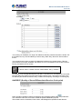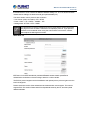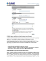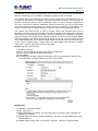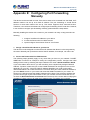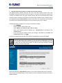
1
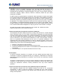
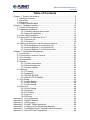
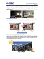
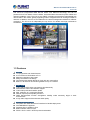
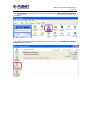
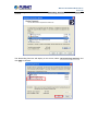
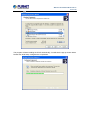
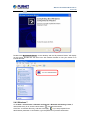
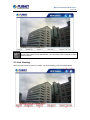
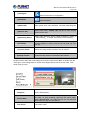
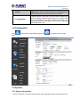
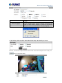
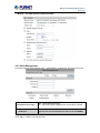
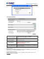
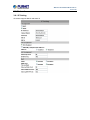
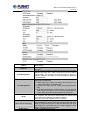
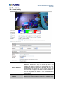
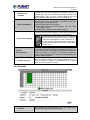
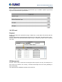
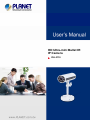
HD Ultra-mini Bullet IR IP Camera ICA-3110 HD Ultra-mini Bullet IR IP Camera ICA-3110 HD Ultra-mini Bullet IR IP Camera ICA-3110 Copyright Copyright © 2014 by PLANET Technology Corp. All rights reserved. No part of this publication may be reproduced, transmitted, transcribed, stored in a retrieval system, or translated into any language or computer language, in any form or by any means, electronic, mechanical, magnetic, optical, chemical, manual or otherwise, without the prior written permission of PLANET. PLANET makes no representations or warranties, either expressed or implied, with respect to the contents hereof and specifically disclaims any warranties, merchantability or fitness for any particular purpose. Any software described in this manual is sold or licensed "as is". Should the programs prove defective following their purchase, the buyer (and not PLANET, its distributor, or its dealer) assumes the entire cost of all necessary servicing, repair, and any incidental or consequential damages resulting from any defect in the software. Further, PLANET reserves the right to revise this publication and to make changes from time to time in the contents hereof without obligation to notify any person of such revision or changes. All brand and product names mentioned in this manual are trademarks and/or registered trademarks of their respective holders. Federal Communication Commission Interference Statement This equipment has been tested and found to comply with the limits for a Class B digital device, pursuant to Part 15 of FCC Rules. These limits are designed to provide reasonable protection against harmful interference in a residential installation. This equipment generates, uses, and can radiate radio frequency energy and, if not installed and used in accordance with the instructions, may cause harmful interference to radio communications. However, there is no guarantee that interference will not occur in a particular installation. If this equipment does cause harmful interference to radio or television reception, which can be determined by turning the equipment off and on, the user is encouraged to try to correct the interference by one or more of the following measures: 1. Reorient or relocate the receiving antenna. 2. Increase the separation between the equipment and receiver. 3. Connect the equipment into an outlet on a circuit different from that to which the receiver is connected. 4. Consult the dealer or an experienced radio technician for help. FCC Caution To assure continued compliance, for example, use only shielded interface cables when connecting to computer or peripheral devices. Any changes or modifications not expressly approved by the party responsible for compliance could void the user’s authority to operate the equipment. This device complies with Part 15 of the FCC Rules. Operation is subject to the following two conditions: (1) This device may not cause harmful interference, and (2) this device must accept any interference received, including interference that may cause undesired operation. Federal Communication Commission (FCC) Radiation Exposure Statement This equipment complies with FCC radiation exposure set forth for an uncontrolled environment. In order to avoid the possibility of exceeding the FCC radio frequency exposure limits, human proximity to the antenna shall not be less than 20 cm (8 inches) during normal operation. HD Ultra-mini Bullet IR IP Camera ICA-3110 Safety This equipment is designed with the utmost care for the safety of those who install and use it. However, special attention must be paid to the dangers of electric shock and static electricity when working with electrical equipment. All guidelines of this and of the computer manufacture must therefore be allowed at all times to ensure the safe use of the equipment. CE Mark Warning This is a Class B product. In a domestic environment, this product may cause radio interference, in which case the user may be required to take adequate measures. WEEE Regulation To avoid the potential effects on the environment and human health as a result of the presence of hazardous substances in electrical and electronic equipment, end users of electrical and electronic equipment should understand the meaning of the crossed-out wheeled bin symbol. Do not dispose of WEEE as unsorted municipal waste; they should be collected separately. Revision User’s Manual for PLANET HD Ultra-mini Bullet IR IP Camera Model: ICA-3110 Rev: 1.1 (June.2014) Part No. EM-ICA-3110 HD Ultra-mini Bullet IR IP Camera ICA-3110 Table of Contents Chapter 1. Product Introduction ......................................................................5 1.1 Package Contents ..............................................................................5 1.2 Overview.............................................................................................5 1.3 Features..............................................................................................7 1.4 Product Specifications ........................................................................8 Chapter 2. Hardware Interface......................................................................10 2.1 Physical Descriptions........................................................................10 2.2 Hardware Installation ........................................................................11 2.2.1 Installing camera with screws .................................................11 2.2.2 Network Installation ................................................................11 2.3 Initial Utility Installation......................................................................12 2.4 Using UPnP of Windows XP or 7 ......................................................15 2.4.1 Windows XP ...........................................................................15 2.4.2 Windows 7 ..............................................................................19 2.5 Setting up ActiveX to use the Internet Camera .................................21 2.5.1 Internet Explorer 6 for Windows XP........................................21 2.5.2 Internet Explorer 7 for Windows XP........................................22 2.5.3 Internet Explorer 7 for Windows Vista.....................................23 Chapter 3. Web-based Management ............................................................24 3.1 Introduction .......................................................................................24 3.2 Connecting to Internet Camera.........................................................24 3.3 Live Viewing......................................................................................25 3.4 Configuration ....................................................................................27 3.5 System..............................................................................................27 3.5.1 System Information.................................................................27 3.5.2 User Management ..................................................................29 3.5.3 System Update .......................................................................30 3.6 Network.............................................................................................31 3.6.1 IP Setting ................................................................................31 3.6.2 Advanced................................................................................33 3.6.3 PPPoE & DDNS .....................................................................39 3.6.4 Mail & FTP & SAMBA .............................................................41 3.7 A/V Setting ........................................................................................42 3.7.1 Image Setting .........................................................................42 3.7.2 Video Setting ..........................................................................44 3.7.3 Audio Setting ..........................................................................46 3.8 Event List ..........................................................................................48 3.8.1 Event Setting ..........................................................................48 3.8.2 Schedule.................................................................................49 3.8.3 I/O Setting...............................................................................50 3.8.4 Log List ...................................................................................51 3.8.5 SD card...................................................................................51 Appendix A: I/O Configuration ......................................................................54 Appendix B: PING IP Address ......................................................................57 Appendix C: 3GPP Access............................................................................58 Appendix D: PLANET DDNS Application ......................................................59 Appendix E: Configuring Port Forwarding Manually .....................................61 Appendix F: Troubleshooting & Frequently Asked Questions.......................64 Appendix G: Micro SD Card Compatibility.....................................................68 HD Ultra-mini Bullet IR IP Camera ICA-3110 Chapter 1. Product Introduction 1.1 Package Contents The package should contain the following items: z Camera unit x 1 z User’s Manual CD x 1 z Quick Installation Guide x 1 z Stand Package x 1 1. If any of the above items are missing, please contact your dealer immediately. 2. Using the power supply that is not the one included in the Internet Camera packet will cause damage and void the warranty for this product. 1.2 Overview Superior Full HD Grade Video Quality PLANET ICA-3110 PoE IP Camera provides high resolution images for round-the-clock surveillance over IP networks. It supports H.264 and JPEG compression formats and delivers excellent picture quality in Full HD resolutions at 25 frames per second (fps). It is perfect for remote and discreet monitoring of indoor areas such as home, small businesses, boutiques, restaurants, hotels, residences, etc. Mini Design for Easy Installation The ICA-3110 is an ultra lightweight IP camera in compact size, thus offering a quick and simple installation on the ceilings or walls inside of houses and buildings. Installation can be finished in less than 60 seconds. HD Ultra-mini Bullet IR IP Camera ICA-3110 Exceptional Image Quality Together with powerful image processing attributes like Wide Dynamic Range (WDR) and Dimension Noise Reduction (DNR) technologies, the ICA-3110 is able to filter the intense backlight surrounding a subject and remove noises from video signal. The result is that an extremely clear and exquisite picture quality can be produced even under any challenging lighting conditions. Advanced Event Management The ICA-3110 supports a number of advanced features to enhance surveillance flexibility and event management capabilities. The advanced features include inputs/outputs for connecting to external devices such as door sensors and relays to activate light or closed doors. Full Surveillance during Day & Night Functionality For a clear surveillance image both in the day and night, the ICA-3110 built-in 7 IR LEDs can offer IR distance of up to 5 meters. Its 720P resolution makes the image still clear even at night. The ICA-3110 also is equipped with ICR 2.8mm / F1.8, and auto-iris function which can automatically adjust the amount of light that passes through the lens. Thus, the ICA-3110 is able to maintain clear images 24 hours a day. HD Ultra-mini Bullet IR IP Camera ICA-3110 Flexible Installation and Power Functionality The ICA-3110 incorporates IEEE 802.3af Power over Ethernet technology and can be powered from a PoE Switch via the network, which eliminates the need for power cables and reduces installation costs. The ICA-3110 is ONVIF-compliant and therefore interoperable with other brands in the market, greatly supporting users to integrate with their existing surveillance network. In addition, the ICA-3110 includes 64-CH central management software for efficient monitoring. The ICA-3110 is indisputably the top choice for reliable and high performance surveillance. 1.3 Features ¾ Camera 1/4" progressive scan CMOS sensor 0.2 lux minimum illumination at F1.8 Maximum resolution 1280 x 800 Easily-recessed mount design Convenient nano-design blends in nicely with any surrounding Built-in 7 IR LEDs for IR monitoring distance of up to 5 meters ¾ Video / Audio H.264 and M-JPEG video compression simultaneously Simultaneous multi-H.264 streams support H.264 main profile and baseline profile Max. resolution of 1 mega-pixel at 30fps DNR to improve picture quality at low lux WDR Enhancement function strengthens visibility under extremely bright or dark environments 2-way audio support with enhanced audio quality ¾ Network and Configuration Compliant with IEEE 802.3af PoE interface for flexible deployment Auto MDI/MDI-X supported Supports IPv6 in addition to IPv4 Built-in Samba client for NAS RTSP / UPnP / 3GPP / HTTPS protocols selectable HD Ultra-mini Bullet IR IP Camera ICA-3110 3GPP for 3G mobile remote applications Access anytime & anywhere for PLANET easy DDNS ¾ Easy Installation & Management ONVIF compliant for interoperability Tamper and motion detection for unauthorized changes Micro SD card local video recording supported Easy configuration and management via Windows-based utility or web interface Cam Viewer 3 central management software supported Digital Input/Output for integration with sensors and alarms 1.4 Product Specifications Model ICA-3110 Camera Image Device 1/4" progressive scan CMOS sensor Lens Fixed lens 2.8mm, F1.8 Angle of view : horizontal: 77.78 degrees / vertical: 49.55 degrees Min Illuminator Color : 0.2 Lux (AGC ON) B / W: 0.1 Lux (AGC ON) Electronic Shutter Auto, 1 / 5 ~ 1 / 10,000 sec Effective Pixels 1280 x 800 pixels LEDs 7 LEDs, 850nm IR distance 5 meters Video Video Compression H.264 / M-JPEG Video Resolutions H.264: 1280 x 800 / 1280 x 720 / 640 x 480 / 320 x 240 / 176 x 144 M-JPEG: 1280 x 800 / 1280 x 720 / 640 x 480 / 320 x 240 / 176 x 144 Frame Rate Up to 30fps for all resolution Image Setting Brightness, Contrast, Hue, Saturation, Sharpness, AGC, Shutter Time, Sense-up, D-WDR, Anti Fog, Lens Distortion Correction, Flip, Mirror, Day & Night adjustable, Red Gain and Blue Gain, Denoise Streaming Simultaneously multi-profile streaming M-JPEG streaming over HTTP Supports 3GPP mobile surveillance Controllable frame rate and bandwidth Constant and variable bit rate (H.264) Audio Audio Streaming 2-way audio Audio Compression RTSP: G.711 64kbps, G.726 32, 24kbps 3GPP: AMR Microphone Built-in microphone input Audio Output 3.5mm phone jack Network and Configuration Network Standard IEEE 802.3 10Base-T IEEE 802.3u 100Base-TX Protocol IPV6, IPv4, HTTP, HTTPS, SNMP, QoS/DSCP, Access list, IEEE 802.1X, RTSP, TCP/IP, UDP, SMTP, FTP, PPPoE, DHCP, DDNS, NTP, UPnP, 3GPP, SAMBA, Bonjour HD Ultra-mini Bullet IR IP Camera ICA-3110 Security Password protection, IP address filtering, HTTPS encrypted data transmission, 802.1X Port-based authentication for network protection, QoS/DSCP Users 10 clients on-line monitoring at the same time System Integration Application Programming Interface Open SDK/API for software integration ONVIF Compliant Alarm Triggers Intelligent video motion detection and external input 3-zone video motion detection Alarm Events File upload via FTP, Samba, SD card or email External output activation General Power Requirements IEEE 802.3af Class 3 Power Consumption PoE Max: 2.88W (IR ON); 2.23W (IR Off) Operating Temperature 0 ~ 45 degrees C Operating Humidity 10 ~ 95% (non-condensing) Weight 135g Dimensions (Φ x L) 44 x 95 mm Emission CE, FCC Connectors 10/100 Mbps Ethernet, RJ-45 Terminal block for 1 alarm input, 1 output and factory default reset Micro SD/SDHC card (Max. 32GB, Class 6) HD Ultra-mini Bullet IR IP Camera ICA-3110 Chapter 2. Hardware Interface 2.1 Physical Descriptions Real Panel Interface LAN(PoE) Micro-SD Factory Default Reset Description The LAN socket is a RJ-45 connector for connections to 10Base-T Ethernet or 100Base-TX Fast Ethernet cabling. This Ethernet port built N-Way protocol can detect or negotiate the transmission speed of the network automatically. Please use Category 5 cable to connect the Network Camera to a 100Mbps Fast Ethernet network switch or hub. User can insert a micro SD card into this slot for event recording. This button is hidden in the pinhole. This button is used to restore the all factory default settings. Sometimes restarting the camera will make the system back to a normal state. If the system still got problems after restart, user can restore the factory default settings and install it again. To restore the device, please follow the steps below: 1. Unplug the power jack, then press and hold the reset button. 2. Power on the camera. Don’t release the button during the system booting. 3. It will take around 30 seconds to boot the camera. 4. Release the button (remove the pin from the reset hole). The camera should now be back to factory default. 5. Login the camera using the default IP (http://192.168.0.20), and username (admin), password (admin). Restoring the factory default setting will lose all the previous settings including IP address forever. User needs to run the IPInstaller program to search the device and configure it to let the device work properly again. DI/DO Connect the power and the Ethernet with the camera. The HD Ultra-mini Bullet IR IP Camera ICA-3110 four-colored wires are used for I/O connection. About I/ O setting. Name Function GND DI DO Audio Out GND Digital signal input Digital signal output Audio-out jack allows this device to output audio signal. 2.2 Hardware Installation 2.2.1 Installing camera with screws 1. Attach the Camera to the stand included. 2. Place the Camera on the table or fix it onto the ceiling or wall Use three screws to fix the Network Camera onto the ceiling or wall. You could also put the Network Camera on the table directly. Fasten it with Screws 2.2.2 Network Installation 1. Connecting an Ethernet cable Connect the LAN cable on the camera to the network device (hub or switch). If there is an IEEE802.3af PoE switch in your network, you can connect the camera LAN cable to this PoE switch to obtain power. The power adapter is unnecessary when Internet camera is connected to a PoE switch. 2. Attach the power supply Plug in power adapter and connect to power source. After power on, the camera will start to operate. HD Ultra-mini Bullet IR IP Camera ICA-3110 1. Only use the power adapter supplied with Internet camera; otherwise, the product may be damaged. 2. The power adapter is unnecessary when Internet camera is connected to a PoE switch. Otherwise, the product may be damaged when Internet camera is connected to a PoE switch and power adapter simultaneously. 3. PoE (Power over Ethernet) Power over Ethernet (PoE) is a technology that integrates power into a standard LAN infrastructure. It enables power to be provided to the network device, such as an IP phone or a network camera, using the same cable as that used for network connection. It eliminates the need for power outlets at the camera locations and enables easier application of uninterruptible power supplies (UPS) to ensure 24 hours a day, 7 days a week operation. 2.3 Initial Utility Installation This chapter shows how to quickly set up your H.264 camera. The camera is with the default settings. However to help you find the networked camera quickly the windows utility PLANET IP Installer can search the cameras in the network that will help you to configure some basic settings before you start advanced management and monitoring. 1. Insert the bundled CD into the CD-ROM drive to launch the auto-run program. Once completed, a welcome menu screen will appear. 2. Click the “IPinstaller” hyperlink; you will see the dialog box below. If the welcome screen does not appear, click “Start” at the taskbar. Then, select “Run” and type “D:\Utility\PLANETIPinstaller\PLANETIPinstaller.exe”, assuming D is your CD-ROM drive. HD Ultra-mini Bullet IR IP Camera ICA-3110 3. OS: Windows XP SP2 or above. If the following “Windows Security Alert” pops up, please click “Unblock”. 4. The GUI of IP Installer is as follows (Default IP: 192.168.0.20). (1) IP Installer will search all IP cameras connected to LAN. The user can click “Search Device” to search again. (2) Click one of IP cameras listed on the left side of IP Installer, then the network configuration of that IP Camera will be listed on the right side. If parameters change, click on “Submit”. Then, the network configuration will be changed. Just click “OK” to reboot HD Ultra-mini Bullet IR IP Camera ICA-3110 (3) Please make sure the subnet of PC IP address and IP CAM IP address are the same. IP CAM IP address: 192.168.0.20 PC IP address: 192.168.0.100 (4) Different Subnets: IP CAM IP address: 192.168.0.20 PC IP address: 192.168.1.100 (5) To Change PC IP addresses: Control PanelÆNetwork ConnectionsÆLocal Area Connection PropertiesÆInternet Protocol (TCP/IP) ÆProperties Please make sure your IP Camera and PC have the same Subnet. If not, please change IP Camera IP subnet or PC IP subnet accordingly. (6) A quick way to access remote monitoring is to left-click the mouse twice on a selected IP camera listed on “Device list” of PLANET IP Installer. An IE browser will be opened. (7) Then, please key in the default User Name: “admin” and Password “admin” in the following message box. HD Ultra-mini Bullet IR IP Camera ICA-3110 (8) If the user name and password are input correctly, the following web page will be displayed. 2.4 Using UPnP of Windows XP or 7 2.4.1 Windows XP UPnP™ is short for Universal Plug and Play, which is a networking architecture that provides compatibility among networking equipment, software, and peripherals. This device is an UPnP enabled device. If the operating system, Windows XP, of your PC is UPnP enabled, the device will be very easy to configure. Use the following steps to enable UPnP settings only if your operating system of PC is running Windows XP. Please note that MS Windows 2000 does not support UPnP feature. Go to Start > Settings, and Click Control Panel. HD Ultra-mini Bullet IR IP Camera ICA-3110 The “Control Panel” will display on the screen and double-click “Add or Remove Programs” to continue. The “Add or Remove Programs” will display on the screen and click Add/Remove Widows Components to continue. HD Ultra-mini Bullet IR IP Camera ICA-3110 The following screen will appear, select “Networking Services” and click “Details” to continue. The “Networking Services” will display on the screen, select “Universal Plug and Play” and click “OK” to continue. HD Ultra-mini Bullet IR IP Camera ICA-3110 Please click “Next” to continue. The program will start installing the UPnP automatically. You will see the pop-up screen below. Please wait while Setup configures the components. HD Ultra-mini Bullet IR IP Camera ICA-3110 Please click “Finish” to complete the UPnP installation Double-click “My Network Places” on the desktop, and the “My Network Places” will display on the screen. Double-click the UPnP icon with Internet Camera to view your device in an internet browser. ICA-3110-00304FA29270 2.4.2 Windows 7 Go to Start > Control Panel > Network and Internet > Network and Sharing Center, if network discovery is off; click the arrow button to expand the section. Click Turn on network discovery, and then click Apply. If you are prompted for an administrator password or confirmation, type the password or provide confirmation. HD Ultra-mini Bullet IR IP Camera ICA-3110 HD Ultra-mini Bullet IR IP Camera ICA-3110 2.5 Setting up ActiveX to use the Internet Camera The Internet Camera web pages communicate with the Internet Camera using an ActiveX control. The ActiveX control must be downloaded from the Internet Camera and installed on your PC. Your Internet Explorer security settings must allow for the web page to work correctly. To use the Internet Camera, user must set up his IE browser as follows: 2.5.1 Internet Explorer 6 for Windows XP From your IE browse Î ”Tools” Î ”Internet Options…” Î ”Security” ΔCustom Level…”, please set up your “Settings” as follows: Set the first 3 items • Download the signed ActiveX controls • Download the unsigned nsigned ActiveX controls • Initialize and script the ActiveX controls not masked as safe to Prompt HD Ultra-mini Bullet IR IP Camera ICA-3110 By now, you have finished your entire PC configuration for Internet Camera. 2.5.2 Internet Explorer 7 for Windows XP From your IE browse Î ”Tools” Î ”Internet Options…” Î ”Security” ΔCustom Level…”, please set up your “Settings” as follows: Set the first 3 items • Allows previously unused ActiveX control to run… • Allows Scriptlets • Automatic prompting for ActiveX controls By now, you have finished your entire PC configuration for Internet Camera. HD Ultra-mini Bullet IR IP Camera ICA-3110 2.5.3 Internet Explorer 7 for Windows Vista From your IE browse Î ”Tools” ( ”Internet Options…” ( ”Security” ( ”Internet” (”Custom Level…”, please set up your “Settings” as follows: • Enable “Automatic prompting for ActiveX controls” • Prompt “Initialize and script active controls not marked….” From your IE browse Î ”Tools” Î ”Internet Options…” ( ”Security” ( ”Trusted Sites” (”Custom Level…”, please set up your “Settings” as follows: • Enable “Automatic prompting for ActiveX controls” • Prompt “Initialize and script active controls not marked….” By now, you have finished your entire PC configuration for Internet Camera. HD Ultra-mini Bullet IR IP Camera ICA-3110 Chapter 3. Web-based Management This chapter provides setup details of the Internet Camera’s Web-based Interface. 3.1 Introduction The Internet Camera can be configured with your Web Browser. Before configuring, please make sure your PC is under the same IP segment as Internet Camera. 3.2 Connecting to Internet Camera A. Use the following procedures to establish a connection from your PC to the Internet Camera. B. Once connected, you can add the camera to your Browser’s Favorites or Bookmarks. Start the web browser on the computer and type the IP address of the camera. The Default IP: “http://192.168.0.20“ The login window of Internet Camera will appear, Default login username and password is: admin and admin If the User Name and Password have been changed with PLANET IP Installer, please enter the new User Name and Password here. Web browser may display the “Security Warming” window, select “Yes” to install and run the ActiveX control into your PC. HD Ultra-mini Bullet IR IP Camera ICA-3110 After the ActiveX control is installed and run, the first image will be displayed. If you log in the camera as an ordinary user, setting function will be not available. If you log in the camera as the administrator, you can perform all the settings provided within the device. 3.3 Live Viewing Start-up screen will be as follows no matter you are an ordinary user or an administrator. HD Ultra-mini Bullet IR IP Camera ICA-3110 (1)Configure Get into the menu for configuration. (2)Snapshot Video Snapshot (3)Status Bar Show system time, video resolution, and video refreshing rate (4)Screen Size Select video screen “default, 1/2x, 1x, 2x” for view currently camera screen size (5)Streaming Select Select video streaming source (When streaming 2 setting in 『Video Setting』 is closed, this function will not display) (6) Chatting Please check this item to execute two-way audio function, then connect speaker to camera so that user can hear the voice from PC. (7) Online Visitor Shows how many people connect to this IP camera (8) Relay Control Control the relay which is connected to this camera Double-click the video and it will change to full screen mode. Press “Esc” or double-click the video again, it will change back to normal mode. Right-click the mouse on the video, it will show a pop-up menu. Snapshot Save a JPEG picture. Record Start Record the video in the local PC. It will ask you where to save the video. To stop recording, right-click the mouse again. Select “Record Stop”. The video format is AVI. Use Microsoft Media Player to play the recorded file. Full Screen Full-screen mode. HD Ultra-mini Bullet IR IP Camera ICA-3110 ZOOM Enable zoom-in and zoom-out functions. Select “Enable digital zoom” option first within the pop-up dialogue box and then drag and drop the bar to adjust the zoom factors. FrameBufferSec Build a buffer to accumulate several video frames and play at a regular interval. This function can make video smooth-going when the Network speed is slow and lag. If you select “100”, the interval between every frame is fixed to 100 mSec. The slower the Network is, the bigger value should be selected. The default value is null. 3.4 Configuration Click page. to get into the administration page. Click to go back to the live video 3.5 System 3.5.1 System Information 1. Server Information: Set up the camera name, select language, and set up the camera time. HD Ultra-mini Bullet IR IP Camera ICA-3110 Server Name Select language This is the Camera name. This name will show on the IP Installer. There are English, Traditional Chinese, Simplified Chinese, French, Russian, Italian, Spanish, German, Portuguese and Polish to select. When changed, it will show the following dialogue box for the confirmation of changing language. 2. OSD Setting: Select a position where date & time stamp / text showing on screen. Moreover, click Text Edit to adjust the OSD contents which include Size and Alpha of text. Finally, click button to reserve the setting. HD Ultra-mini Bullet IR IP Camera ICA-3110 3. Server time setting:Select options to set up time - “NTP”, “Synchronize with PC’s time”, “Manual”, “The date and time remain the same”. 3.5.2 User Management IP camera supports three different users -- administrator, general user, and anonymous user. Anonymous User Login Add user Yes:Allow anonymous login No:Need user name & password to access this IP camera Type the user name and password, and then click “Add/Set”. Click “edit” or “delete” to modify the user HD Ultra-mini Bullet IR IP Camera ICA-3110 3.5.3 System Update Firmware Upgrade To update the firmware online, click “Browse…” to select the firmware. Then click “Upgrade” to proceed. Reboot System Re-start the IP camera. Factory default Delete all the settings in this IP camera. (Not include IP address) Setting Management User may download the current setting to PC, or upgrade from previous saved setting. Setting download: Right-click the mouse button on Setting Download Æ Select “Save AS…” to save current IP CAM setting in PC Æ Select saving directory Æ Save Upgrade from previous setting: Browse Æ search previous setting Æ open Æ upgrade Æ Setting update confirm Æ click index.html to return to main page HD Ultra-mini Bullet IR IP Camera ICA-3110 3.6 Network 3.6.1 IP Setting IP camera supports DHCP and static IP. HD Ultra-mini Bullet IR IP Camera ICA-3110 DHCP Static IP IPv6 Assignment Port Assignment UPnP UPnP Port Forwarding RTSP Server Using DHCP, IP camera will get all the network parameters automatically. Please type in IP address, subnet mask, gateway, and DNS manually. IPv6 is a newer numbering system that provides a much larger address pool than IPv4, which accounts for most of today’s Internet traffic. You can set up IPv6 manually by keying in Address, Gateway, and DNS, or enabling DHCP to assign the IP automatically. User may need to assign a different port to avoid conflict when setting up IP assignment. (1) Web Page Port: setup web page connecting port and video transmitting port (Default: 80) (2) RTSP Port: setup port for RTSP transmitting (Default: 554) (3) RTP Start and End Port: in RTSP mode, you may use TCP and UDP for connecting. TCP connection uses RTSP Port (554). UDP connection uses RTP Start and End Port. This IP camera supports UPnP. If this service is enabled on your computer, the camera will automatically be detected and a new icon will be added to “My Network Places.” Note: UPnP must be enabled on your computer. When the camera is installed under a router, enable UPnP Port Forwarding to let the router open ports so that the video streams can be sent out from a LAN. Set Web Port, Http Port, and RTSP port, and make sure your router supports UPnP and the function has been activated. enable or disable RTSP server HD Ultra-mini Bullet IR IP Camera ICA-3110 RTSP Authentication RTSP port Multicast Setting (Based on the RTSP Server) ONVIF RTSP Keepalive Bonjour LLTD "Disable" means everyone who knows your camera IP Address can link to your camera via RTSP. No username and password are required. Under "Basic" and "Digest" authentication mode, the camera asks the user to give username and password before allows accessing. The password is transmitted as clear text under basic mode, which provides a lower level of security than under digest mode. Make sure your media player supports the authentication schemes RTSP Port: setup port for RTSP transmitting (Default: 554) RTSP Start and End Port: in RTSP mode, you may use TCP and UDP for connecting. TCP connection uses RTSP Port (554). UDP connection uses RTSP Start and End Port. Multicast is a bandwidth conservation technology. This function allows several users to share the same packet sent from IP camera. To use Multicast, appoint IP Address and port here. TTL means the life time of packet, The larger the value is, and the more users can receive the packet. To use Multicast, be sure to enable the function "Force Multicast RTP via RTSP" in your media player. Then key in the RTSP path of your camera: "rtsp://(IP address)/" to receive the multicast. The IP camera supports ONVIF v1.01 / v1.02 / v2.10 standard for to integration. Under ONVIF connection, the video will be transmitted by RTSP. Be sure to enable the RTSP server in IP setting, or you're not able to receive the video via ONVIF. When the function is enabled, the camera checks once in a while if the user who links to the camera via ONVIF still keeps connecting. If the connection had been broken, the camera stop transmitting video to user. This function enables MAC systems to link to this IP camera. Key in the name here. The web browser "Safari" also has Bonjour function. Tick "Include Bonjour" in the bookmark setting, and you can see the IP camera appearing under the bonjour category. Click the icon to connect the IP camera. If your PC supports LLTD, enable this function then you can check the connection status, properties, and device position (like IP address) of this IP Camera in the network map. In the computer running Windows Vista or Windows 7, you can find LLTD through the path: Call out the Control Panel → Network and Internet → Network and Sharing Center → Click "See full map" 3.6.2 Advanced Https (Hypertext Transfer Protocol Secure) HD Ultra-mini Bullet IR IP Camera ICA-3110 Https can help protect streaming data transmission over the internal on the higher security level. You can select the connection type. "Https" means user cannot connect the camera via Http protocol. The Https path will be: "https://(IP address)/". If you select "Http & Https", both the Http and Https path can be used to access the camera. Remove the existing setting: Before setting new request, please remove old secure identification. Select "Http" connection type and click "Remove". Created Request: Setting the secure identification and apply it There are two ways to set Certificate- Install Signed Certificate or Create Self-Signed Certificate. HD Ultra-mini Bullet IR IP Camera ICA-3110 SNMP (Simple Network Management Protocol) SNMP provides a simple framework for administering networked hardware. To manage the IP camera, you have to prepare an MIB browser or similar tools first. SNMPv1, SNMPv2c, and SNMPv3 can be enabled simultaneously. SNMPv1 and SNMPv2: The term "Community name" in SNMPv1 and SNMPv2c can be roughly regarded as key. The person who has the community name has the authority to read or edit the information of IP camera via SNMP. Tick the box to enable SNMPv1 or SNMPv2c protocol, and specify the community name for write (read and write) and read (read-only). The user who use read community name to access the IP camera cannot modify any data of this camera. SNMPv3: For data security reason, the authentication and encryption assurances are added when developing SNMPv3. The user has to give not only the security name (the same as HD Ultra-mini Bullet IR IP Camera ICA-3110 "community name" in v1&v2c, or sometimes we call it "context name") but the password in order to access the IP camera. Please set security name, authentication type, authentication password, encryption type, encryption password of write and read respectively. The password must be 8~64 bits in length. Different from SNMPv1 and v2c, the user have to create an account when using SNMPv3. In the account parameters, key in the security name and password you set in the camera to get accessing. SNMPv1/SNMPv2 Trap: Trap is a mechanism that allows the managed device to send messages to manager instead of waiting passively for polling from the manager. Specify the trap event. When those events happen, the camera will send the ring message to the Trap Address, which is usually the manager's IP address. Trap Community means the community that can receive the trap message. • Cold Start: The camera starts up or reboots. • Setting changed: The SNMP setting is changed. • Network Disconnected: The network connection was broken down. (The camera will send trap messages after the network being connected again) • V3 Authentication Failed: A SNMPv3 user account tries to get authentication but failed. (Due to incorrect password or community) • SD Insert / Remove: A Micro SD card is inserted or removed. HD Ultra-mini Bullet IR IP Camera ICA-3110 Access List You can deny an IP address or a range of IP address so that they cannot access the IP camera. Tick the "enable" box, key in the IP address you want to deny, select” deny" then click” Add" to add it to the list. You can also choose to deny a range of IP addresses but allow one or several of them. Take the picture above for example, IP address 192.168.50.151~161 is not allowed to connect to the camera, but only 192.168.50.159 can access. In the list "allow" condition must be ranked before "deny" condition. For example, if we exchange the sequence, set "Deny: 192.168.50.151~192.168.50.161" for the first item and "Allow:192.168.50.159" for the second item in the list, the IP "192.168.50.159" turns out to be denied by the camera because the "deny" condition has the priority according to our ranking way. QoS/DSCP (Quality of Server/Differentiated Services Code-point) DSCP specifies a simple mechanism for classifying and managing network traffic and provide QoS on IP networks. DSCP is a 6-bit in the IP header for packet classification purpose. The number 0~63 for Live Stream, Event / Alarm, and Management represent the ratio that the HD Ultra-mini Bullet IR IP Camera ICA-3110 bandwidth is divided. For example, if you set 5, 10, and 20 for the three items, then the bandwidth of the three items is 5:10:20. There is no difference between setting "0, 0, 0" or "63, 63, 63" because under these two settings, the three items will get equal bandwidth (1/3). The three stream control protocols are as follows: • Live Stream (Video and audio): RTP / RTSP • Event / Alarm : FTP / SMTP / SAMBA / SIP • Management: HTTPS / HTTP / SNMP The "Management" stream handles both the live view and the setting area of the web page on which the data is transferred via http/https protocol. If you prefer to distribute more bandwidth when using the web browser to access the camera, please adjust the Management stream. IEEE 802.1x IEEE 802.1x is an IEEE standard for port-based Network Access Control. It provides an authentication mechanism to device wishing to attach to a LAN or WLAN. The EAPOL protocol supports service identification and optional point to point encryption over the local LAN segment. Please check what version of the authenticator and authentication server support. This camera supports EAP-TLS method. Please enter ID and password issued by the CA, and then upload related certificates. HD Ultra-mini Bullet IR IP Camera ICA-3110 3.6.3 PPPoE & DDNS PPPoE: Stands for Point to Point Protocol over Ethernet A standard builds on Ethernet and Point-to-Point network protocol. It allows Internet camera to connect to Internet with xDSL or cable connection; it can dial up your ISP and get a dynamic IP address. For more PPPoE and Internet configuration, please consult your ISP. It can directly connect to the xDSL; however, it should be set up on a LAN environment to program the PPPoE information first, and then connect to the xDSL modem. Power on again, then the device will dial on to the ISP connection to the WAN through the xDSL modem. The procedures are: (1) Select “Enabled” to use PPPoE. (2) Key-in username and password for the ADSL connection. (3) Send mail after dialing:When connected to the Internet, it will send a mail to a specific mail account. For the mail setting, please refer to “Mail and FTP” settings. DDNS: Stands for Dynamic Domain Name Server The device supports DDNS. If your device is connected to xDSL directly, you might need this feature. However, if your device is behind a NAT router, you will not need to enable this feature. Because DDNS allows the device to use an easier way to remember naming format rather than an IP address. The name of the domain is like the name of a person, and the IP address is like his phone number. On the Internet we have IP numbers for each host (computer, server, router, and so on), and we replace these IP numbers to easily remember names, which are HD Ultra-mini Bullet IR IP Camera ICA-3110 organized into the domain name. As to xDSL environment, most of the users will use dynamic IP addresses. If users want to set up a web or an FTP server, then the Dynamic Domain Name Server is necessary. For more DDNS configuration, please consult your dealer. Your Internet Service Provider (ISP) provides you with at least one IP address which you use to connect to the Internet. The address you get may be static, meaning it never changes, or dynamic, meaning it’s likely to change periodically. Just how often it changes, it depends on your ISP. A dynamic IP address complicates remote access since you may not know what your current WAN IP address is when you want to access your network over the Internet. The solution to the dynamic IP address problem comes in the form of a dynamic DNS service. The Internet uses DNS servers to look up domain names and translates them into IP addresses. Domain names are just easy to remember aliases for IP addresses. A dynamic DNS service is unique because it provides a means of updating your IP address so that your listing will remain current when your IP address changes. There are several excellent DDNS services available on the Internet and best of all they’re free to use. One such service you can use is www.DynDNS.org. You’ll need to register with the service and set up the domain name of your choice to begin using it. Please refer to the home page of the service for detailed instructions or refer to Appendix E for more information. DynDns.org, the procedures are: (1) Enable this service (2) Key-in the DynDNS server name, user name, and password. (3) Set up the IP Schedule update refreshing rate. (4) Click “Apply” (5) If setting up IP schedule update too frequently, the IP may be blocked. In general, it is recommended to schedule update every day (1440 minutes). DDNS Status (1) Updating:Information update (2) Idle:Stop service (3) DDNS registration successful, can now log by http://<username>.ddns.camddns.com: Register successfully. (4) Update Failed, the name is already registered:The user name has already been used. Please change it. (5) Update Failed, please check your Internet connection:Network connection failed. HD Ultra-mini Bullet IR IP Camera ICA-3110 (6) Update Failed, please check the account information you provide:The server, user name, and password may be wrong. This model adds Planet easy DDNS that when enabled, this function will occur host name with PLANET DDNS and end six of MAC automatically. User does not need to go to web of www.planetddns.com to apply for the new account. 3.6.4 Mail & FTP & SAMBA To send out the video via mail, FTP and Samba, please set up the configuration first. Mail Setting: Set up the server address and account information of your e-mail. Click “Apply” to save the setting, then use “Test” button to test the server connection. A message box will tell you “OK!” If it works, a test e-mail will be sent to receiver’s mail address. FTP Setting: Set up the server address and account information of your FTP. Click “Apply” to save the setting, then use “Test” button to test the server connection. A message box will tell you “OK!” if it works, and a test file will be uploaded to FTP space. HD Ultra-mini Bullet IR IP Camera ICA-3110 In PORT mode, the FTP server builds the connection to the user’s data port actively. However, from the user-side firewall’s standpoint, the action of connecting from FTP server is often considered to be dangerous and should be blocked. In PASV mode, the problem is solved: The FTP server waits for the data transmission connection built by the user. Make sure that the server supports the mode you select. Samba Setting: Select this option to send the media files via a network neighborhood when an event is triggered. Click “Apply” to save the setting, then use “Test” button to test the server connection. A message box will tell you “OK!” if it works, and a test document will be created in the location. If the test fails, check the sharing setting of your location folder. The folder properties must be “shared” and the permissions must be “Full Control” as the picture. Samba only supports one layer folder. 3.7 A/V Setting 3.7.1 Image Setting For the security and privacy purposes, there are three areas that can be set up for privacy mask. Click Area button first and drag an area on the above image, and remember to save your setting. The masked area will not show on both the live viewing and recording. HD Ultra-mini Bullet IR IP Camera ICA-3110 (1) Image adjust Brightness, Contrast, Hue, Saturation, Sharpness can be adjusted here. The available values are: -4, -3, -2, -1, 0, 1, 2, 3, 4 (2) AGC The sensitivity of the camera can adjust to the environmental lighting. Enable this function for getting brighter image on low light, but the level of noise may also increase. The available values are: 8x, 16x, 24x, 32x (3) Shutter Time Choose as the location of your camera or fixed shutter time. The shorter the shutter time is the less light the camera receives and the image becomes darker. (4) Sense-Up This function increases the sensitivity of camera to get brighter image at night. The smaller the value you select, the slower the shutter speed becomes so that the image will get brighter, and moving subjects might be blurred. (5) D-WDR Digital wide dynamic range. This function enables the camera to reduce the contrast in the view to avoid dark zones as a result of over and under exposure. If the Input resolution is 30fps, the default value is fixed on ENABLED. The available values are: OFF, 1, 2, 3, 4, 5, 6, 7, 8 (6) Anti Fog Improve the image clarity on environments presenting high levels of fog or smoke. (7) Lens Distortion Correction Correct the image in the borders due to the lens angles. The available values are: OFF, 1, 2, 3, 4, 5, 6, 7, 8 (8) Video Orientation Flip or mirror the image. HD Ultra-mini Bullet IR IP Camera ICA-3110 (9) Day & Night The camera can detect the light level of the environment. If you choose "Light Sensor Mode", the image will be turned black and white at night in order to keep a clear image. To set light sensor mode, appoint a Lux standard of switching D/N. The current Lux value is provided for reference. Under "Times Mode" the switch time of Color / Black and white will be according to the given time. You can also control it by choosing "Color" or "B/W”. (10) Red / Blue gain Set the values for Red / Blue gain. The available values are: -5, -4, -3, -2, -1, 0, 1, 2, 3, 4, 5 (11) Denoise This function is able to filter the noise and blur from the image and show a clearer view. You can set the values for 2D and 3D filters. 3.7.2 Video Setting Video System: click the drop down list to select the system type “NTSC/PAL” and TV Output (analog signal). Basic Mode: Resolution 1280x800@30fps, 320x240@30fps, 1280x720@30fps, 176x144@30fps 640x480@30fps, (Max Video Frame Rate for both streaming combined is 30 FPS) Profile Choose between Main or Baseline. There are 5 levels: Best/ High/ Standard/ Medium/ Low Quality The higher the quality is, the bigger the file size is. Not good for internet transmission. HD Ultra-mini Bullet IR IP Camera ICA-3110 Video Frame Rate The video refreshing rate per second. The max Value is affected by the input resolution you choose. Video Format H.264 and JPEG. RTSP Path Set the RTSP output connecting route. Advanced Mode: Resolution 1280x800@30fps, 320x240@30fps, 1280x720@30fps, 176x144@30fps 640x480@30fps, (Max Video Frame Rate for both streaming combined is 30 FPS) Profile Chose between Main or Baseline. There are CBR (Constant Bit Rate) and VBR (Variable Bit Rate) to use. Bitrate Control Mode CBR:32Kbps~10Mbps (the higher the CBR is, the better the video quality is) VBR:1(Low) ~10(High) – Compression rate, the higher the compression rate, the lower the picture quality is; vice versa. The balance between VBR and network bandwidth will affect HD Ultra-mini Bullet IR IP Camera ICA-3110 picture quality. Please carefully select the VBR rate to avoid picture breaking up or lagging. Video Quantitative The quality parameter of VBR. You can choose 1~10 compression rate. The higher the value is, the higher the image quality is. Video Bitrate The quality parameter of CBR. You can choose 32kbps ~ 8Mbps. The higher the value is, the higher the image quality is. Video Frame Rate The video refreshing rate per second. The max value is affected by the input resolution you choose. GOP Size It means “Group of Pictures”. The higher the GOP is, the better the quality is. Video Format H.264 and JPEG RTSP Path RTSP output connecting route 3GPP Streaming mode: The RTSP here is separated from the RTSP setting in the "IP SETTING".3GPP Streaming can still work even you select "disabled" in the RTSP server option of IP Setting. 3GPP Resolution: 640 x 480 @15fps, 320 x 240 @ 15fps, 176 x 144 @ 15fps Video compression: H.264, Audio compression: AMR. 3GPP Path: 3GPP output connecting route. If the IP address of your camera is 192.168.40.150, and you key in "3g" in the column, the 3GPP path will be rtsp://192.168.40.150/3g. 3.7.3 Audio Setting The IP camera supports 2-way audio. User can send audio from IP camera’s built-in microphone to remote PC; User can also send audio from remote PC to IP camera’s external speaker. (1) Audio from IP camera’s built-in microphone to local PC: select “Enable” to start this function. The Audio compression format can be chosen from 3 options. You can also adjust the volume of 2-way audio. HD Ultra-mini Bullet IR IP Camera ICA-3110 (2) Audio from local PC to IP Camera: Check “chatting” on the browsing page. HD Ultra-mini Bullet IR IP Camera ICA-3110 3.8 Event List 3.8.1 Event Setting Motion Detection IP camera allows 3-area motion detection. When motion is triggered, it can send the video to some specific mail addresses, transmit the video to remote ftp server and SAMBA, and trigger the relay. To set up the motion area, click “Area Setting”. Using mouse to drag and draw the area. The same operation for area 2 and 3. If you select "save to SD card", the video or snapshot will be saved to Micro SD card. If you also tick E-mail/ FTP/ Samba of "Log" option, the motion detection log will be sent to E-mail/ FTP/ Samba simultaneously. Interval For example, if you select "10 sec" here, once the motion is detected and action is triggered, it cannot be triggered again within 10 seconds. Based on the schedule Record File Setting HD Ultra-mini Bullet IR IP Camera ICA-3110 When the option box is ticked, only during the selected schedule time the motion detection is enabled. That is, for example, the 11th hour of Monday has not been colored in the schedule table, then no action will be triggered even the camera detects motion during 11:00~12:00 on Monday. IP camera allows 3 different types of recording file to change its record size. When motion/alarm is triggered, there are 3 different types of recording modes: (1) AVI File (With Record File Setting ) (2).Multi-JPEG (With Record File Setting), only with JPEG compression format. (3) Single JPEG (Single File with Interval Setting) Pre Alarm and Post Alarm setups for video start and end time when motion detects I/O, or other devices got triggered. Record Time Setting Network Dis-connected Network IP check Pre/Post Alarm record time is based on record time setting and IP cam built-in Ram memory. Limited by IP cam built-in Ram Memory, when information is too much or video quality set too high, it will cause recording frame to drop or decrease on post alarm recording time. To avoid video loss, the camera will start to save the video to local SD card when it detects no network connection. The video recording will continuously be saved into SD card and divided into every 10 minutes a file until the network is reconnected successfully. The oldest file will be deleted if the capacity of SD card is full. Key in the target IP address and interval. The camera checks once in a while according to the setting interval time if it can link to the target IP address. If connection fails, the camera starts to save the video to SD card 3.8.2 Schedule Schedule After complete the schedule setup, the camera data will be recorded according to the schedule setup. HD Ultra-mini Bullet IR IP Camera ICA-3110 Snapshot After enable the snapshot function, user can select the storage position of snapshot file, the interval time of snapshot and the reserved file name of snapshot. Interval The interval between two snapshots. 3.8.3 I/O Setting The ICA-3110 supports 1 input/1 output. When input is triggered, it can send the video to some specific mail addresses, transmit the video to remote ftp server, and trigger the relay and SAMBA. Alarm Input Setting The GPIO I/O port input activates related action when I/O input is triggered. Interval For example, if you select "10 sec" here, once the motion is detected and action is triggered, it cannot be triggered again within 10 seconds. Based on the schedule When the option box is ticked, only during the selected scheduled time the I/O is enabled. That is, for example, the 11th hour of Monday has not been colored in the scheduled table, then no action will be triggered even the camera detects input signal during 11:00~12:00 on Monday. GPIO Output Setting The GPIO I/O port output activates On/Off Switch, Slide Switch or Pan/Tilt Module for use with relay box. On Off Switch The camera triggers the external devise and lasts for 10 seconds. You can turn off the alarm manually by clicking "off" at the right bottom of the live video page. Time Switch The camera triggers the external device and lasts for certain of time according to the interval setting, and the user is not allowed to break off the alarm manually. Please connect to propriety relay box to reduce the risk of electric shock and damage. HD Ultra-mini Bullet IR IP Camera ICA-3110 3.8.4 Log List Sort by System Logs, Motion Detection Logs and I/O Logs. In addition, System Logs and I/O Logs won’t lose data due to power failure. 3.8.5 SD card Playback Please Insert Micro SD card before using it. Make sure t o push Micro SD card into the slot completely. Click the date listed on this page and it shows the list of the video. The video format is AVI. Click the video to start Microsoft Media Player to play it. To delete the video, check it, and then click "Del". SD Management Choose “The 1st day” means the recoding file will be kept for one day. For example, it is five o’clock now. Choose “The 1st day”. The files will be kept from five o’clock yesterday to five o’clock today. The oldest file will be deleted if the Micro SD card is full. HD Ultra-mini Bullet IR IP Camera ICA-3110 The use of the SD card will affect the operation of the IP Camera slightly, such as affecting the frame rate of the video. Copy to PC You can insert the Micro SD card into PC and read the files directly, or use FlashGet instead to download the files from IP camera. (In this way you do not need to pull out Micro SD card from the camera.) To use FlashGet for downloading the image and video data from the Micro SD card, please follow the steps: Open FlashGet, select "File” → "Import" → "Import list", and find the link list file you just saved. The file name may be called "SD_list". HD Ultra-mini Bullet IR IP Camera ICA-3110 FlashGet will show you the link list, and you can tick the files you want to copy to your PC. Give the directory path in the new download window, and remember to enable "Login to Server": Key in the IP camera user name and password. Click OK to start download FlashGet is a free software that can be downloaded from FlashGet official website. The example above is based on FlashGet ver.1.9.6.1073 HD Ultra-mini Bullet IR IP Camera ICA-3110 Appendix A: I/O Configuration 1. I/O Connection A. Please connect the G & DO pin to the external relay (buzzer) device. When no event happens, DO output is 5V (DO and GND are disconnected). When the camera detects event happening and triggers external alarm, DO output is 0V (DO and GND are connected). B. Please connect the G & DI pin to the external trigger device. If you select "N.O" in "Input sensor setting", when external devise or circuit makes DI and GND pin connected, the camera input alarm is triggered, and then camera will execute the action user has set, for example, send snapshot to E-mail address. If you select "N.C" in "Input sensor setting", when external devise or circuit makes DI and GND pin disconnected, the camera input alarm is triggered, and then camera will execute the action user has set, for example, send snapshot to E-mail address. HD Ultra-mini Bullet IR IP Camera ICA-3110 C. I/O PIN definition • GND (Ground): Initial state is LOW • DO (Digital Output): DC 5V • DI (Digital Input): Max. 50mA, DC 5V 2. I/O Setup A. Click I/O Setting from the system setup page via IE, and check “Out1” to enable I/O signal. B. Output Test After the external input and output hardware is installed, you can use the "Relay Out" bottom on the live video page to test if DO / Relay Out works. 1) OnOff Switch mode: Click "ON" and the camera will trigger the external output device. For example, your alarm buzzer will continuously ring. You can manually break off the output signal by clicking "OFF". HD Ultra-mini Bullet IR IP Camera ICA-3110 2) Time Switch mode: Click "Pulse" and the camera will trigger the external output device for several seconds. The duration length is according to the "interval" setting in Output Setting. HD Ultra-mini Bullet IR IP Camera ICA-3110 Appendix B: PING IP Address The PING (stands for Packet Internet Groper) command is used to detect whether a specific IP address is accessible by sending a packet to the specific address and waiting for a reply. It’s also a very useful tool to confirm whether or not Internet camera installed or if the IP address conflicts with any other device over the network. If you want to make sure the IP address of Internet camera, utilize the PING command as follows: z Start a DOS window. z Type ping x.x.x.x, where x.x.x.x is the IP address of the Internet camera. The replies, as illustrated below, will provide an explanation to the problem. If you want to detect any other device that conflicts with the IP address of Internet camera, you also can utilize the PING command but you must disconnect the Internet camera from the network first. HD Ultra-mini Bullet IR IP Camera ICA-3110 Appendix C: 3GPP Access To use the 3GPP function, in addition to the previous section, you might need more information or configuration to make this function work. To use the 3GPP function, it is strongly recommended to install the Networked Device with a public and fixed IP address without any firewall protection. RTSP Port: Port 554 is the default for RTSP service. However, sometimes, some service providers change this port number for some reasons. If so, user needs to change this port accordingly. Dialing procedure: 1. Choose a verified player (PacketVideo or Realplayer) 2. Use the following default URL to access: rtsp://IP-Address/3g Where host is the host name or IP address of the camera. Compatible 3G mobile phone: Please contact your dealer to get the approved list of compatible 3G phones. Besides IP camera and 3G mobile phone, you will also need to make sure the ISP and company have provided the 3GPP service to you. HD Ultra-mini Bullet IR IP Camera ICA-3110 Appendix D: PLANET DDNS Application Configuring PLANET DDNS steps: Step 1 Enable DDNS option through accessing web page of the ICA-3110. Step 2 Select on DDNS server provided, and register an account if you do not use yet. Step 3 After login, please add your device. Step 4 Set your camera IP to public. HD Ultra-mini Bullet IR IP Camera ICA-3110 Step 5 Fill out the blank of the DDNS setting. (The user name and password here are the same as your registered user name and password on the planetddns website.) Step 6 After the setting is done, for example, we can enter http://frankt.planetddns.com/ to access the camera, and you can see your device photo and “Ping Status” is green on the planetddns website. HD Ultra-mini Bullet IR IP Camera ICA-3110 Appendix E: Configuring Port Forwarding Manually The device can be used with a router. If the device wants to be accessed from the WAN, its IP address needs to be set up as a fixed IP address. The port forwarding or Virtual Server function of router also needs to be set up. This device supports UPnP traversal function. Therefore, user could use this feature to configure port forwarding of NAT router first. However, if user needs to configure port forwarding manually, please follow the steps below: Manually installing the device with a router on your network is an easy 3–step procedure as following: 1. Assign a local/fixed IP address to your device 2. Access the Router with Your Web browser 3. Open/Configure Virtual Server Ports of Your Router 1. Assign a local/fixed IP address to your device The device must be assigned a local and fixed IP Address that allows it to be recognized by the router. Manually set up the device with a fixed IP address, for example, 192.168.0.100. 2. Access the Router with Your Web browser The following steps generally apply to any router that you have on your network. PLANET WNRT-620 is used as an example to clarify the configuration process. Configure the initial settings of the router by following the steps outlined in the router’s Quick Installation Guide. If you have cable or DSL service, you will most likely have a dynamically assigned WAN IP Address. ‘Dynamic’ means that your router’s WAN IP address can change from time to time depending on your ISP. A dynamic WAN IP Address identifies your router on the public network and allows it to access the Internet. To find out what your router’s WAN IP Address is, go to the Status screen on your router and locate the WAN information for your router. As shown on the following page the WAN IP Address will be listed. This will be the address that you will need to type in your web browser to view your camera over the Internet. Be sure to uncheck the Reset IP address at next boot button at the top of the screen after modifying the IP address. Failure to do so will reset the IP address when you restart your computer. HD Ultra-mini Bullet IR IP Camera ICA-3110 Your WAN IP Address will be listed here. 3. Open/set Virtual Server Ports to enable remote image viewing The firewall security features built into the router and most routers prevent users from accessing the video from the device over the Internet. The router connects to the Internet over a series of numbered ports. The ports normally used by the device are blocked from access over the Internet. Therefore, these ports need to be made accessible over the Internet. This is accomplished using the Virtual Server function on the router. The Virtual Server ports used by the camera must be opened through the router for remote access to your camera. Follow these steps to configure your router’s Virtual Server settings z Click Enabled. z Enter a unique name for each entry. z Select Both under Protocol Type (TCP and UDP) z Enter your camera’s local IP Address (e.g., 192.168.0.100, for example) in the Private IP field. z If you are using the default camera port settings, enter 80 into the Public and Private Port section, click Add. A check mark appearing before the entry name will indicate that the ports are enabled. Some ISPs block access to port 80. Be sure to check with your ISP so that you can open the appropriate ports accordingly. If your ISP does not pass traffic on port 80, you will need to change the port the camera uses from 80 to something else, such as 8080. Not all routers are the same, so refer to your user manual for specific instructions on how to open ports. Enter valid ports in the Virtual Server section of your router. Please make sure to check the box on this line to enable settings. Then the device can be accessed from WAN by the router’s WAN IP Address. HD Ultra-mini Bullet IR IP Camera ICA-3110 By now, you have finished your entire PC configuration for this device. HD Ultra-mini Bullet IR IP Camera ICA-3110 Appendix F: Troubleshooting & Frequently Asked Questions Features The video and audio codec is adopted in the device. The device utilizes H.264, MPEG-4 and M-JPEG triple compression to provide high quality images. Where H.264 and MPEG-4 are standards for video compression and M-JPEG is a standard for image compression. The audio codec is defined as AMR for 3GPP and G.711 for RTSP streaming. The maximum number of user that accesses the device simultaneously. The maximum number of users is limited to 10. However, it also depends on the total bandwidth accessed to this device from clients. Install this device The network cabling is required for the device. The device uses Category 5 UTP cable allowing 10 and/or 100 Base-T networking. The device will be installed and work if a firewall exists on the network. If a firewall exists on the network, port 80 is open for ordinary data communication. The HTTP port and RTSP port need to be opened on the firewall or NAT router. The username and password for the first time or after factory default reset Username = admin and Password = admin. Note that it’s all case sensitivity. Forgot the username and password Follow the steps below: (1)Remove power, and press and hold the button in the back of IP camera. (2)Power on the camera. Don’t release the button during the system booting. (3)It will take around 30 seconds to boot the camera. (4)Release the button when camera finishes proceed. (5)Re-login the camera using the default IP (http://192.168.0.20), and username (admin), password (admin). Forgot the IP address of the device. Check IP address of device by using the PLANET IP Installer program or by UPnP discovery or set the device to default by Reset button. z Re-power the device if cannot find the unit within 1 minute. z Do not connect device over a router. PLANET IP Installer program cannot detect device over a router. z If IP address is not assigned to the PC that runs PLANET IP Installer program, then PLANET IP Installer program cannot find device. Make sure that IP address is assigned to the PC properly. z Antivirus software on the PC might interfere with the setup program. Disable the firewall of the antivirus software during setting up this device. z Check the firewall setting of your PC or Notebook. PLANET IP Installer program cannot find the device. HD Ultra-mini Bullet IR IP Camera ICA-3110 Internet Explorer does not seem to work well with the device Make sure that your Internet Explorer is version 6.0 or later. If you are experiencing problems, try upgrading to the latest version of Microsoft’s Internet Explorer from the Microsoft webpage. PLANET IP Installer program fails to save the network parameters. Network may have trouble. Confirm the parameters and connections of the device. UPnP NAT Traversal Cannot work with NAT router Maybe NAT router does not support UPnP function. Please check user’s manual of router and turn on UPnP function. Some IP cameras are working but others failed Maybe too many IP cameras have been installed on the LAN, and then NAT router is out of resource to support more cameras. You could turn off and on NAT router to clear out of date information inside router. Access this device z Maybe the IP Address of the Network Camera is already being used by another device or computer. To confirm this possible problem, disconnect the Network Camera from the network first, and then run the PING utility to check it out. z Maybe it’s the network cable. Try correcting your network cable and configuration. Test the network interface by connecting a local computer to the Network Camera via a crossover cable. z Make sure the Internet connection and setting is ok. z Make sure the IP address of Internet Explorer you entered is correct. If the Network Camera has had a dynamic address, it may have changed since you last checked it. z Network congestion may prevent the web page from appearing quickly. Wait for a while. The IP address and Subnet Mask of the PC and Network Camera must be in the same class of the private IP address on the LAN. Cannot access the login page and other web pages of the Network Camera from Internet Explorer z Make sure the http port used by the Network Camera, default=80, is forward to the Network Camera’s private IP address. z The port number assigned in your Network Camera might not be available via Internet. Check your ISP for available port. z The proxy server may prevent you from connecting directly to the Network Camera. You are advised not to use the proxy server. z Confirm that Default Gateway address is correct. z The router needs Port Forwarding feature. Refer to your router's manual for details. z Packet Filtering of the router may prohibit access from an external network. Refer to your router's manual for details. z Access the Network Camera from the Internet with the global IP address of the router and port number of Network Camera. z Some routers reject the global IP address to access the Network Camera on the same LAN. Access with the private IP address and correct port number of Network Camera. z When you use DDNS, you need to set Default Gateway and DNS HD Ultra-mini Bullet IR IP Camera ICA-3110 server address. Image or video does not appear on the main page. z If it’s not working after following the above procedure, reset Network Camera to default setting and install it again. z The first time the PC connects to Network Camera, a pop-up Security Warning window will appear to download ActiveX Controls. When using Windows XP, or Vista, log on with an appropriate account that is authorized to install applications. z Network congestion may prevent the Image screen from appearing quickly. You may choose lower resolution to reduce the required bandwidth. How to check whether the device’s ActiveX is installed on your computer Go to C:\Windows\Downloaded Program Files and check to see if there is an entry for the file “Web Watch2 Control”. The status column should show “Installed”. If the file is not listed, make sure your Security Settings in Internet Explorer are configured properly and then try reloading the device’s home page. Most likely, the ActiveX control did not download and install correctly. Check your Internet Explorer security settings and then close and restart Internet Explorer. Try to browse and log in again. Internet Explorer displays the following message: “Your current security settings prohibit downloading ActiveX controls”. Setup the IE security settings or configure the individual settings to allow downloading and scripting of ActiveX controls. The device works locally but not externally. The unreadable characters are displayed. Frame rate is slower than the setting. Image Transfer on e-mail or FTP does not work. z Might be caused from the firewall protection. Check the Internet firewall with your system or network administrator. The firewall may need to have some settings changed in order for the device to be accessible outside your LAN. z Make sure that the device isn’t conflicting with any other web server running on your LAN. z Check the configuration of the router settings to allow the device to be accessed outside your local LAN. z Check the bandwidth of Internet connection. If the Internet bandwidth is lower than target bit rate, the video streaming will not work correctly. Use the operating system of the selected language. Set the Encoding or the Character Set of the selected language on the Internet Explorer. z The traffic of the network and the object of the image affect the frame rate. The network congestion causes frame rate slower than the setting. z Check the bandwidth of Internet connection. If the Internet bandwidth is lower than target bit rate, the video streaming will not work correctly. z Ethernet switching hub can smooth the frame rate. z Default Gateway and DNS server address should be set up correctly. z If FTP does not work properly, ask your ISP or network administrator about the transferring mode of FTP server. HD Ultra-mini Bullet IR IP Camera ICA-3110 Video quality of the device The focus on the Camera is bad. The lens is dirty or dust is attached. Fingerprints, dust, stain, etc. on the lens can degrade the image quality. z Adjust White Balance. z To ensure the images you are viewing are the best they can be, set the Display property setting (color quality) to 16bit at least and 24 bit or higher if possible within your computer. z The configuration on the device image display is incorrect. You need to adjust the image related parameters such as brightness, contrast, hue and sharpness properly. z If the object is dark, the image will flicker. Make the condition around the Camera brighter. The color of the image is poor or strange. Image flickers. HD Ultra-mini Bullet IR IP Camera ICA-3110 Appendix G: Micro SD Card Compatibility The following is the Micro SD Card recommended: Transcend SanDisk SDHC SDHC SD SD SDHC SDHC SDHC SD SD SD SDHC SDHC SDHC SDHC SDHC SDHC SDHC class4 class4 class4 class4 class6 class6 class6 class6 class6 class6 class10 class10 class10 class4 class4 class4 class4 16GB 32GB 16GB 32GB 4GB 8GB 16GB 4GB 8GB 16GB 4GB 8GB 16GB 4GB 8GB 16GB 32GB