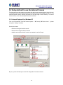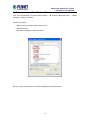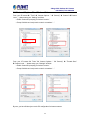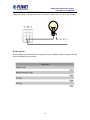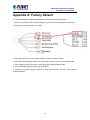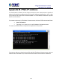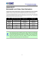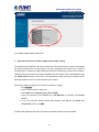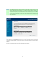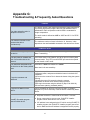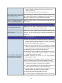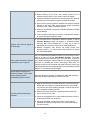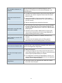
1
2 Mega-Pixel Outdoor
IR IP Camera
ICA-HM316 / IC A-HM316W
2 Mega‐Pixel Outdoor IR IP Camera ICA‐HM316 / ICA‐HM316W Copyright
Copyright © 2013 by PLANET Technology Corp. All rights reserved. No part of this
publication may be reproduced, transmitted, transcribed, stored in a retrieval system, or
translated into any language or computer language, in any form or by any means, electronic,
mechanical, magnetic, optical, chemical, manual or otherwise, without the prior written
permission of PLANET.
PLANET makes no representations or warranties, either expressed or implied, with respect
to the contents hereof and specifically disclaims any warranties, merchantability or fitness for
any particular purpose. Any software described in this manual is sold or licensed "as is".
Should the programs prove defective following their purchase, the buyer (and not PLANET,
its distributor, or its dealer) assumes the entire cost of all necessary servicing, repair, and
any incidental or consequential damages resulting from any defect in the software. Further,
PLANET reserves the right to revise this publication and to make changes from time to time
in the contents hereof without obligation to notify any person of such revision or changes.
All brand and product names mentioned in this manual are trademarks and/or
registered trademarks of their respective holders.
Federal Communication Commission Interference Statement
This equipment has been tested and found to comply with the limits for a Class B digital
device, pursuant to Part 15 of FCC Rules. These limits are designed to provide reasonable
protection against harmful interference in a residential installation. This equipment generates,
uses, and can radiate radio frequency energy and, if not installed and used in accordance
with the instructions, may cause harmful interference to radio communications. However,
there is no guarantee that interference will not occur in a particular installation. If this
equipment does cause harmful interference to radio or television reception, which can be
determined by turning the equipment off and on, the user is encouraged to try to correct the
interference by one or more of the following measures:
1. Reorient or relocate the receiving antenna.
2. Increase the separation between the equipment and receiver.
3. Connect the equipment into an outlet on a circuit different from that to which the receiver
is connected.
4. Consult the dealer or an experienced radio technician for help.
FCC Caution
To assure continued compliance. (example-use only shielded interface cables when
connecting to computer or peripheral devices). Any changes or modifications not expressly
approved by the party responsible for compliance could void the user’s authority to operate
the equipment.
This device complies with Part 15 of the FCC Rules. Operation is subject to the Following
two conditions: ( 1 ) This device may not cause harmful interference, and ( 2 ) this Device
must accept any interference received, including interference that may cause undesired
operation.
Federal Communication Commission (FCC) Radiation Exposure Statement
This equipment complies with FCC radiation exposure set forth for an uncontrolled
environment. In order to avoid the possibility of exceeding the FCC radio frequency
exposure limits, human proximity to the antenna shall not be less than 20 cm (8 inches)
during normal operation.
2
2 Mega‐Pixel Outdoor IR IP Camera ICA‐HM316 / ICA‐HM316W Safety
This equipment is designed with the utmost care for the safety of those who install and use it.
However, special attention must be paid to the dangers of electric shock and static electricity
when working with electrical equipment. All guidelines of this and of the computer
manufacture must therefore be allowed at all times to ensure the safe use of the equipment.
CE Mark Warning
This is a Class B product. In a domestic environment, this product may cause radio
interference, in which case the user may be required to take adequate measures.
WEEE Regulation
To avoid the potential effects on the environment and human health as a result of
the presence of hazardous substances in electrical and electronic equipment, end
users of electrical and electronic equipment should understand the meaning of
the crossed-out wheeled bin symbol. Do not dispose of WEEE as unsorted
municipal
waste and have to collect such WEEE separately.
Revision
User’s Manual for PLANET 2Mega-Pixel Outdoor IR PoE / Wireless IP Camera
Model: ICA-HM316 / ICA-HM316W
Rev: 2.00 (January. 2013)
Part No. EM-ICAHM316 / ICA-HM316W
3
2 Mega‐Pixel Outdoor IR IP Camera ICA‐HM316 / ICA‐HM316W Table of Content
Chapter 1. Product Introduction .................................................................................... 6
1.1 Package Contents ............................................................................................. 6
1.2 Product Description ........................................................................................... 6
1.3 Features .............................................................................................................. 7
1.4 Product Specification......................................................................................... 8
Chapter 2. Hardware Interface .................................................................................... 10
2.1 Physical Description........................................................................................ 10
2.1.1 Identification of ICA-HM316 cable ..................................................... 10
2.1.2 ICA-HM316 I/O Control Instruction.................................................... 11
2.2 Hardware Installation ...................................................................................... 13
2.2.1 Physical Installation ............................................................................. 13
Chapter 3. Initial Utility Installation.............................................................................. 15
3.1 Search and Configure Network by PLANET IP Installer ........................... 15
3.2 Setup ActiveX to use the Internet Camera .................................................. 20
3.2.1 Internet Explorer 6 for Windows XP .................................................. 20
3.2.2 Internet Explorer 7 for Windows XP .................................................. 21
3.2.3 Internet Explorer 7 for Windows Vista............................................... 22
3.3 Using UPnP of Windows XP or Vista......................................................... 23
3.3.1 Windows XP.......................................................................................... 23
3.3.2 Windows Vista ...................................................................................... 28
Chapter 4. Installation Guide ....................................................................................... 31
4.1 System Requirements..................................................................................... 31
4.2 Before You Begin ............................................................................................... 31
4.2.1Connecting to Internet Camera ........................................................... 31
Chapter 5. Web Configuration for Live View ................................................................ 34
5.1 Live View........................................................................................................... 34
5.2 Configuration .................................................................................................... 37
Chapter 6. Camera configuration.................................................................................. 38
6.1 System............................................................................................................... 38
6.1.1 System Information .............................................................................. 38
6.1.2 User Management................................................................................ 40
6.1.3 System Update ..................................................................................... 41
6.2 Network ............................................................................................................. 42
6.2.1 IP Setting ............................................................................................... 42
6.2.2 PPPoE.................................................................................................... 43
6.2.3 DDNS ..................................................................................................... 43
6.2.4 Mail & FTP & SAMBA .......................................................................... 47
6.2.5 Wireless Setting.................................................................................... 47
6.3 A/V Setting ........................................................................................................ 50
6.3.1 Image Setting........................................................................................ 50
6.3.2 Video Setting......................................................................................... 50
6.3.3 Audio....................................................................................................... 53
6.4 Event List .......................................................................................................... 54
6.4.1 Event Setting......................................................................................... 54
6.4.2 Schedule................................................................................................ 55
6.4.3 I/O Setting.............................................................................................. 56
6.4.4 Log List................................................................................................... 58
Appendix A: Factory Default ......................................................................................... 59
4
2 Mega‐Pixel Outdoor IR IP Camera ICA‐HM316 / ICA‐HM316W Appendix B: PING IP Address...................................................................................... 60
Appendix C: 3GPP Access ........................................................................................... 61
Appendix D: Bandwidth and Video Size Estimation ................................................. 62
Appendix E: Planet DDNS Application........................................................................ 63
Appendix F: Configure Port Forwarding Manually .................................................... 64
Appendix G: Troubleshooting & Frequently Asked Questions ................................ 67
5
2 Mega‐Pixel Outdoor IR IP Camera ICA‐HM316 / ICA‐HM316W Chapter 1.
Product Introduction
1.1 Package Contents
The package should contain the followings:
z
IP Camera Unit x 1
z
Power Adapter x 1
z
Screw package x 1
z
Stand x 1
z
5dbi Antenna x 1 (ICA-HM316W only)
z
User’s Manual CD-ROM x 1
z
Quick Installation Guide x 1
NOTE:
If any of the above items are missing, please contact your dealer
immediately.
2. Using the power supply that is not the one included in Internet Camera
packet will cause damage and void the warranty for this product.
1.
1.2 Product Description
Superb UXGA Quality with outdoor-ready for Professional Surveillance
The PLANET ICA-HM316 / ICA-HM316W Network Camera with IR Illuminator is a high
resolution camera for round-the-clock surveillance over IP networks. This camera supports
H.264, MPEG-4, and JPEG compression formats and delivers excellent picture quality in 2
Mega-Pixel resolutions at 15 frames per second (fps). The ICA-HM316W provides users High
performance 802.11b/g/n connectivity and secured wireless transmission up to 150Mbps
through the IEEE 802.11b/g/n wireless technology and WEP / WPA encryptions. The IP66-rated
housing protects the camera body against rain and dust and ensures operation under extreme
weather conditions, which makes it an ideal solution for outdoor applications, e.g. surveillance of
buildings, roads, parking areas, garages, railway stations and airports.
Day & Night functionality
To adapt to constantly changing lighting conditions, the ICA-HM316 / ICA-HM316W come with a
removable IR-cut filter and built-in IR illuminators, which enables the camera to provide color
video when there is sufficient light, and black/white video in dark conditions. The camera is able
to maintain clear images 24 hours a day.
Exceptional Image quality with Varifocal
With 3.6~16mm Varifocal lens, the ICA-HM316 / ICA-HM316W meet various demand of
installations, for instance, traffic monitoring on two more lanes or focus on one specified lane.
The result is that an extremely clear and exquisite picture quality.
Advanced event management
The ICA-HM316 / ICA-HM316W also supports a number of advanced features that give the
camera increased flexibility and capabilities, including Auto-iris for improve the image quality to
6
2 Mega‐Pixel Outdoor IR IP Camera ICA‐HM316 / ICA‐HM316W avoid over exposure, AV out for perform the two-way audio function and inputs/outputs for
connecting external devices such as door sensors and relays to activate light or close doors.
Flexible installation and Power functionality
The ICA-HM316 / ICA-HM316W incorporate Power over Ethernet supplies power to the camera
via the network, eliminating the need for power cables and reducing installation costs. The
ICA-HM316 is ONVIF-compliant and therefore interoperable with other manufacturer’s products,
it’s also included 64-CH central management software; the ICA-HM316 / ICA-HM316W is
indisputably the top choice for reliable and high performance surveillance.
1.3 Features
¾
■
■
■
■
■
¾
■
■
■
■
¾
■
■
■
■
¾
■
■
■
■
■
■
■
Camera
1/3.2” 2MP progressive scan CMOS sensor
3.6~16 mm Vari-focal, DC Auto-iris Lens
0 lux Minimum Illumination at F1.2
Maximum resolution 1600 x 1200
Removable IR-cut Filter for Day & Night Function
Video / Audio
H.264 / MPEG-4 and M-JPEG video compression simultaneously
Simultaneous multi-stream support
Up to 30fps for 1280 x 720 and 15fps for 1600 x 1200 resolutions
Two-way audio support with enhanced audio quality
Network and Configuration
Compliant with IEEE 802.3af PoE interface for flexible deployment (ICA-HM316 only)
IEEE 802.11b/g/n wireless LAN with WEP and WPA encryption (ICA-HM316W only)
Auto MDI/MDI-X supported
RTSP / UPnP / 3GPP / HTTPS protocols selectable
Easy Installation & Management
Onvif compliant for interoperability
Built-in 35 IR Illuminators, effective up to 25 Meters
IP66 outdoor classifications for rigorous environment
Built-in Samba client for NAS
3GPP for 3G mobile remote applications
Digital Input/Outputs for integration with sensors and alarms
Cam Viewer 3 Central management software supported
7
2 Mega‐Pixel Outdoor IR IP Camera ICA‐HM316 / ICA‐HM316W 1.4 Product Specification
Model
ICA-HM316
ICA-HM316W
Camera
Image Device
1/3.2” 2 Mega-Pixel progressive scan CMOS sensor
Lens
Vari-focal 3.6~16 mm, DC Auto-iris
Mechanical IR Cut Filter
Angle of view : horizontal: 20.8 ~ 75.4 Degree / vertical: 15.7 ~ 54.9 Degree
Min Illuminator
IR Illumination LED
Effective Pixels
0 lux @ F1.2
IR LED*35, 850nm
Built-in IR illuminators, Effective up to 25 meter
1600 x 1200 pixels
Image
Video Encoder
H.264 / MPEG-4 / M-JPEG
H.264: UXGA / 720p / SXGA / VGA / QVGA / QCIF
Video Profile
M-JPEG: UXGA / 720p / SXGA / VGA / QVGA
MPEG-4: QCIF (Only for 3GPP)
Frame Rate
Image Setting
Streaming
Up to 30fps for all resolutions
Brightness, sharpness, contrast, AGC, Night Mode
Text, time and date overlay
Simultaneously multi-profile streaming
M-JPEG streaming over HTTP
Supports 3GPP mobile surveillance
Controllable frame rate and bandwidth
Constant and variable bit rate (MPEG-4 / H.264)
Audio
Audio Streaming
Two-way Audio
Audio Encoder
RTSP:G.711
3GPP:AMR
Microphone
External microphone input
Audio Output
Phone Jack
Network and Configuration
Network Standard
IEEE 802.3 10Base-T
IEEE 802.3 10Base-T
IEEE 802.3u 100Base-TX
IEEE 802.3u 100Base-TX
IEEE 802.11b/g/n
Antenna connector
-
5dBi Dipole Antenna
Frequency
-
2.4GHz ~ 2.4835GHz
RF Transmit Power
-
Receiver Sensitivity
-
OFDM: 14 dbm
CCK: 17 dbm
11b
1M: -90 dbm
8
11M: -85 dbm
2 Mega‐Pixel Outdoor IR IP Camera ICA‐HM316 / ICA‐HM316W 11g
6M: -87 dbm 54M: -70 dbm
11n (BW20)
MCS0: -85 dbm MCS7: -67 dbm
11n (BW40)
MCS0: -84 dbm MCS7: -64 dbm
IEEE 802.11b Standard Data Rates: 1,
2, 5.5 and 11Mbps
IEEE 802.11g Standard Data Rates: 6,
9, 12, 18, 24, 36, 48, 54Mbps
-
Data Rate
IEEE 802.11n Standard Data Rates:
Legacy and High Throughput Modes,
supports 20 / 40MHz Bandwidth
MCS0~7 (150Mbps PHY Rate Rate)
Supported Protocols
IPv4, TCP, UDP, HTTP, SMTP, FTP, NTP, DNS, DDNS, DHCP, UPnP, RTSP,
RTP, RTCP, PPPoE, 3GPP, ICMP
Security
Password protection, user access log
Users
10 simultaneous unicast users
WEP 64/128, WPA, WPA2, TKIP, AES
System Integration
Application Programming
Open API for software integration
Interface
SDK
Alarm Triggers
Intelligent video motion detection and external input
3-zone video motion detection
File upload via FTP, email and SAMBA.
Alarm Events
External output activation
Configurable Pre/Post alarm buffering
General
Power Supply
12V DC, 1A
12V DC, 1A
IEEE 802.3af Class 0
Power Consumption
PoE Max: Max 10.8 W while IR LED
IR on: 6.24W
ON / Max 7.7 W while IR LED OFF
IR off: 4.44W
Housing
Weather-proof IP66-rated housing
Operating Temperature
-20 ~ 50 degree C
Operating Humidity
20 ~ 80% (non-condensing)
Weight
958g
Dimension (Φ x L)
83mm x 180 mm
Emission
CE, FCC
905g
10/100 Mbps Ethernet, RJ-45
DC power jack
Terminal block for 1 alarm input , 1
Connectors
output and factory default reset
External MIC input
10/100 Mbps Ethernet, RJ-45
Optional RP-SMA Type
DC power jack
Terminal block for 1 alarm input , 1
output and factory default reset
External MIC input
Audio out
Audio out
Composited video out
Composited video out
9
2 Mega‐Pixel Outdoor IR IP Camera ICA‐HM316 / ICA‐HM316W Chapter 2.
Hardware Interface
2.1 Physical Description
2.1.1 Identification of ICA-HM316 cable
1. RJ-45 LAN socket: Connect to PC or Hub/Switch.
For connect to 10Base-T Ethernet or 100Base-TX Fast Ethernet cabling. This Ethernet port built
N-Way protocol can detect or negotiate the transmission speed of the network automatically.
Please use CAT-5 cable to connect the Network Camera to a 100Mbps Fast Ethernet network
switch or hub.
2. Power Jack: The input power is DC 12V.
NOTE:
ONLY use package power adapter supplied with the Internet. Otherwise, the
product may be damaged.
3. I/O Control Instruction
I/O terminal connector – used in application, for e.g., motion detection, event triggering, alarm
notifications
4. Video Output
The internet camera also provides composite video output. User can use BNC video cable to
connect the internet camera with a TV monitor or VCR.
5. MIC in (audio in)
Connect a microphone to the network camera.
6. Line out (audio out)
Connect a loud speaker to the network camera. This is for voice alerting and two-way audio.
10
2.1.2 ICA-HM316 I/O Control Instruction 2 Mega‐Pixel Outdoor IR IP Camera ICA‐HM316 / ICA‐HM316W 1. Digital Input (GND + Alarm)
An alarm input for connecting devices that can toggle between an open and closed circuit, for
example: PIRs, door/window contacts, glass break detectors, etc. When a signal is received the
state changes and the input becomes active.
2. Relay output (COM +N.O.) / (COM+N.C.)
An output to relay switch, for example: LEDs, Sirens, etc
3. Digital Input/Alarm Input
1) GND (Ground): Initial state is LOW
2) Alarm: Max. 50mA, DC 3.3V
4. Relay Output
1) N.C. (Normally Close): Max. 1A, 24VDC or 0.2A, 110~240VAC
2) COM: (Common)
3) N.O. (Normally Open): Max. 1A, 24VDC or 0.2A, 110~240VAC
Relay
1. Digital Input connection
11
2 Mega‐Pixel Outdoor IR IP Camera ICA‐HM316 / ICA‐HM316W 2. Relay Output Connection
Or
12
2 Mega‐Pixel Outdoor IR IP Camera ICA‐HM316 / ICA‐HM316W 2.2 Hardware Installation
2.2.1 Physical Installation
1. Connect an Ethernet cable
Connect the LAN cable on the camera to the network device (hub or switch).
NOTE:
If there has an IEEE802.3af PoE switch in your network, you can connect the
camera LAN cable to this PoE switch to obtain power. The power adapter is
unnecessary when Internet camera is connected to a PoE switch.
2. Attach the power supply
Plug in power adapter and connect to power source. After power on, the camera will start to
operate.
NOTE:
1. Only use the power adapter supplied with Internet camera Otherwise, the
product may be damaged.
2. The power adapter is unnecessary when Internet camera is connected to a
PoE switch. Otherwise, the product may be damaged when Internet camera is
connected to a PoE switch and power adapter simultaneously.
3. Attach BNC connector
Connect the video BNC connector to a monitor set if necessary check camera viewing angle
and focus.
4. Attach Speaker to camera (option)
If user needs not only video stream but also audio stream, then the speaker should be
attached to camera.
13
2 Mega‐Pixel Outdoor IR IP Camera ICA‐HM316 / ICA‐HM316W 5. PoE (Power Over Ethernet)
Power over Ethernet (PoE) is a technology that integrates power into a standard LAN
infrastructure. It enables power to be provided to the network device, such as an IP phone or
a network camera, using the same cable as that used for network connection. It eliminates
the need for power outlets at the camera locations and enables easier application of
uninterruptible power supplies (UPS) to ensure 24 hours a day, 7 days a week operation.
14
2 Mega‐Pixel Outdoor IR IP Camera ICA‐HM316 / ICA‐HM316W Chapter 3.
Initial Utility Installation
This chapter shows how to quick set up your H.264 camera. The camera is with the default
settings. However to help you find the networked camera quickly the windows utility PLANET IP
Installer can search the cameras in the network that shall help you to configure some basic setting
before you started advanced management and monitoring.
1. Insert the bundled CD into the CD-ROM drive to launch the auto-run program. Once
completed, a welcome menu screen will appear.
2. Click the “PLANET IPInstaller” hyperlink; you will see the dialog box as below.
NOTE:
If the welcome screen does not appear, click “Start” at the taskbar. Then, select
“Run” and type “D:\Utility\PLANETIPinstaller\PLANETIPinstaller.exe”, assume D
drive is your CD-ROM drive.
When you installed the camera on a LAN environment, you may execute PLANET IP Installer to
discover camera’s IP address and set up related parameters in the camera.
3.1 Search and Configure Network by PLANET IP Installer
When you installed the Camera on a LAN environment, you have two easy ways to search your
Cameras by PLANET IP Installer or UPnP discovery. Here is the way to execute PLANET IP
Installer to discover Camera’s IP address and set up related parameter in a Camera.
Search and Configure Network
1. OS: Windows XP SP2 or above. If the following “Windows Security Alert” popup, please click
“Unblock”.
15
2 Mega‐Pixel Outdoor IR IP Camera ICA‐HM316 / ICA‐HM316W 2. The GUI of IP Installer is as follows (Default IP: 192.168.0.20).
(1) IP Installer will search all IP Cameras connected on LAN. The user can click “Search
Device” to search again.
16
2 Mega‐Pixel Outdoor IR IP Camera ICA‐HM316 / ICA‐HM316W (2) Click one of IP Cameras listed on the left side of IP Installer, then the network configuration
of that IP Camera will be listed on the right side. If parameters changed, click on “Submit”. Then,
the network configuration will be changed. Just click “OK” to reboot
(3) Please make sure the subnet of PC IP address and IP CAM IP address are the same.
IP CAM IP address: 192.168.0.20
PC IP address: 192.168.0.100
(4) Different Subnets:
IP CAM IP address: 192.168.0.20
PC IP address: 192.168.1.100
(5) To Change PC IP addresses:
Control PanelÆNetwork ConnectionsÆLocal Area Connection PropertiesÆInternet Protocol
(TCP/IP) ÆProperties
Please make sure your IP Camera and PC have the same Subnet. If not, please change IP
Camera IP subnet or PC IP subnet accordingly.
17
2 Mega‐Pixel Outdoor IR IP Camera ICA‐HM316 / ICA‐HM316W (6) A quick way to access remote monitoring is to left-click the mouse twice on a selected IP
Camera listed on “Device list” of PLANET IP Installer. An IE browser will be opened.
(7) Then, please key in the default “Username: admin” and “Password: admin” in the
following message box.
(8) If the user name and password are input correctly, the following web page will be displayed.
18
2 Mega‐Pixel Outdoor IR IP Camera ICA‐HM316 / ICA‐HM316W 19
2 Mega‐Pixel Outdoor IR IP Camera ICA‐HM316 / ICA‐HM316W 3.2 Setup ActiveX to use the Internet Camera
The Internet camera web pages communicate with the Internet camera using an ActiveX control.
The ActiveX control must be downloaded from the Internet camera and installed on your PC. Your
Internet Explorer security settings must allow for the web page to work correctly. To use the
Internet camera, user must setup his IE browser as follows:
3.2.1 Internet Explorer 6 for Windows XP From your IE browse Î ”Tools” Î ”Internet Options…” Î ”Security” ΔCustom Level…”, please
setup your “Settings” as follow.
Set the first 3 items
• Download the signed ActiveX controls
• Download the unsigned ActiveX controls
• Initialize and script the ActiveX controls not masked as safe to Prompt
By now, you have finished your entire PC configuration for Internet camera.
20
2 Mega‐Pixel Outdoor IR IP Camera ICA‐HM316 / ICA‐HM316W 3.2.2 Internet Explorer 7 for Windows XP
From your IE browse Î ”Tools” Î ”Internet Options…” Î ”Security” ΔCustom Level…”, please
setup your “Settings” as follow.
Set the first 3 items
• Allow previously unused ActiveX control to run…
• Allows Script lets
• Automatic prompting for ActiveX controls
By now, you have finished your entire PC configuration for Internet camera.
21
2 Mega‐Pixel Outdoor IR IP Camera ICA‐HM316 / ICA‐HM316W 3.2.3 Internet Explorer 7 for Windows Vista From your IE browse Î ”Tools” Î ”Internet Options…” Î ”Security” Î ”Internet” ΔCustom
Level…”, please setup your “Settings” as follow.
• Enable “Automatic prompting for ActiveX controls”
• Prompt “Initialize and script active controls not marked….”
From your IE browse Î ”Tools” Î ”Internet Options…” Î ”Security” Î ”Trusted Sites”
ΔCustom Level…”, please setup your “Settings” as follow.
• Enable “Automatic prompting for ActiveX controls”
• Prompt “Initialize and script active controls not marked….”
By now, you have finished your entire PC configuration for Internet camera.
22
2 Mega‐Pixel Outdoor IR IP Camera ICA‐HM316 / ICA‐HM316W 3.3 Using UPnP of Windows XP or Vista
3.3.1 Windows XP
UPnP™ is short for Universal Plug and Play, which is a networking architecture that provides
compatibility among networking equipment, software, and peripherals. This device is an UPnP
enabled device. If the operating system, Windows XP, of your PC is UPnP enabled, the device will
be very easy to configure. Use the following steps to enable UPnP settings only if your operating
system of PC is running Windows XP.
NOTE:
Windows 2000 does not support UPnP feature.
Go to Start > Settings, and Click Control Panel
23
2 Mega‐Pixel Outdoor IR IP Camera ICA‐HM316 / ICA‐HM316W The “Control Panel” will display on the screen and double click “Add or Remove Programs” to
continue
The “Add or Remove Programs” will display on the screen and click Add/Remove Widows
Components to continue.
24
2 Mega‐Pixel Outdoor IR IP Camera ICA‐HM316 / ICA‐HM316W The following screen will appear, select “Networking Services” and click “Details” to continue
The “Networking Services” will display on the screen, select “Universal Plug and Play” and click
“OK” to continue.
25
2 Mega‐Pixel Outdoor IR IP Camera ICA‐HM316 / ICA‐HM316W Please click “Next” to continue
The program will start installing the UPnP automatically. You will see the below pop-up screen,
please wait while Setup configures the components.
26
2 Mega‐Pixel Outdoor IR IP Camera ICA‐HM316 / ICA‐HM316W Please click “Finish” to complete the UPnP installation
Double-click “My Network Places” on the desktop, the “My Network Places” will display on the
screen and double-click the UPnP icon with Internet camera to view your device in an Internet
browser.
27
2 Mega‐Pixel Outdoor IR IP Camera ICA‐HM316 / ICA‐HM316W 3.3.2 Windows Vista
UPnP™ is short for Universal Plug and Play, which is a networking architecture that provides
compatibility among networking equipment, software, and peripherals. This device is an UPnP
enabled device. If the operating system, Windows Vista, of your PC is UPnP enabled, the device
will be very easy to configure. Use the following steps to enable UPnP settings only if your
operating system of PC is running Windows Vista.
Go to Start > Control Panel > Network and Internet > Network and Sharing Center, and turn
on “Network Discovery”.
28
2 Mega‐Pixel Outdoor IR IP Camera ICA‐HM316 / ICA‐HM316W 29
2 Mega‐Pixel Outdoor IR IP Camera ICA‐HM316 / ICA‐HM316W Double-click “My Network Places“ on the desktop, the “My Network Places” will display on the
screen and double-click the UPnP icon with Internet camera to view your device in an Internet
browser.
30
2 Mega‐Pixel Outdoor IR IP Camera ICA‐HM316 / ICA‐HM316W Chapter 4. Installation Guide
4.1 System Requirements
Network Interface
10/100Base-TX Ethernet
Monitoring System
Recommended for Internet Explorer 8.0 or later
· CPU: Intel Core i3-530
System Hardware
(Suggested)
· Memory Size : 2048 MB (1024 MB or above Recommended )
· VGA card resolution : 1920 x 1200
· VGA card memory : 512 MB or above
· CPU: Intel C-2.8G
System Hardware
(Minimum)
· Memory Size : 512 MB
· VGA card resolution : 1280 x 1024
· VGA card memory : 64 MB
NOTE:
The listed information is minimum system requirements only. Actual requirement will
vary depending on the nature of your environment.
4.2 Before You Begin
The Internet camera can be configured with your Web Browser. Before configure, please make
sure your PC is under the same IP segment with Internet camera.
4.2.1Connecting to Internet Camera
z
Use the following procedure to establish a connection from your PC to the camera.
z
Once connected, you can add the camera to your Browser’s Favorites or Bookmarks.
Start the web browser on the computer and type the IP address of the camera. The Default IP:
“ http://192.168.0.20 “
The login window of Internet camera will appear, Default login username/password is:
admin / admin
31
2 Mega‐Pixel Outdoor IR IP Camera ICA‐HM316 / ICA‐HM316W ;
NOTE:
If the User name and Password have been changed with PLANET IP Installer,
please enter the new User name and Password here.
32
2 Mega‐Pixel Outdoor IR IP Camera ICA‐HM316 / ICA‐HM316W Web browser may display the “Security Warming” window, select “Yes” to install and run the
ActiveX control into your PC.
After the ActiveX control was installed and run, the first image will be displayed.
NOTE:
If you log in the camera as an ordinary user, setting function will be not available. If
you log in the camera as the administrator, you can perform all the settings
provided within the device.
33
2 Mega‐Pixel Outdoor IR IP Camera ICA‐HM316 / ICA‐HM316W Chapter 5. Web Configuration for Live View
5.1 Live View
Start-up screen will be as follow no matter an ordinary users or an administrator.
(1)Configure
Get into the administration page.
(2)Snapshot
.Video Snapshot
(3)Status Bar
Show system time, video resolution, and video refreshing rate.
(4)Screen Size
Select video screen “default, 1/2x, 1x, 2x” for view currently
camera screen size.
(5)Streaming Select
Select video streaming source (When streaming 2 setting in
『Video Setting』 is closed, this function will not display)
34
2 Mega‐Pixel Outdoor IR IP Camera ICA‐HM316 / ICA‐HM316W (6)Chatting Function
.(7)Online Visitor
(8)Relay Control
IP Camera supports 2-way audio. Click the “Chatting” check
box. Then you can use microphone which connects to the PC to
talk to server side, which is IP Camera side
Shows how many people connect to this IP camera.
Control the relay which is connected to this camera.
Double-click the video; it will change to full screen mode. Press “Esc” or double-click the video
again, it will change back to normal mode. Right-Click the mouse on the video, it will show a
pop-up menu.
(1)Snapshot
Save a JPEG picture.
(2)Record Start
Record the video in the local PC. It will ask you where to save
the video. To stop recording, right-click the mouse again. Select
“Record Stop”. The video format is AVI. Use Microsoft Media
Player to play the recorded file.
(3)Mute
Turn of the audio. Click again to turn on it.
(4)Full Screen
Full-screen mode.
(5)ZOOM
Enable zoom-in and zoom-out functions. Select “Enable digital
zoom” option first within the pop-up dialogue box and then drag
and drop the bar to adjust the zoom factors.
35
2 Mega‐Pixel Outdoor IR IP Camera ICA‐HM316 / ICA‐HM316W 36
2 Mega‐Pixel Outdoor IR IP Camera ICA‐HM316 / ICA‐HM316W 5.2 Configuration
Click
video page.
to get into the administration page. Click
37
to go back to the live
2 Mega‐Pixel Outdoor IR IP Camera ICA‐HM316 / ICA‐HM316W Chapter 6. Camera configuration
6.1 System
6.1.1 System Information
1. Server Information: Set up the camera name, select language, and set up the camera time.
Server Name
This is the Camera name. This name will show on the IP
Installer.
Select language
There are English, Traditional Chinese, Simplified
Chinese, French, Russian, Italian, Spanish, German,
Portuguese and Polish to select. When change, it will show
the following dialogue box for the confirmation of
changing language.
2. OSD Setting: Select a position where date & time stamp / text showing on screen.
38
2 Mega‐Pixel Outdoor IR IP Camera ICA‐HM316 / ICA‐HM316W Moreover, click Text Edit can entry to adjust the OSD contents which is including Size and Alpha of text.
Finally, click
button to reserve the setting.
3. Server time setting:Select options to set up time - “NTP”, “Synchronize with PC’s time”,
“Manual”, “The date and time remain the same”.
39
2 Mega‐Pixel Outdoor IR IP Camera ICA‐HM316 / ICA‐HM316W 6.1.2 User Management
IP CAMERA supports three different users, administrator, general user, and anonymous user.
Anonymous User Login
Yes:Allow anonymous login
No:Need user name & password to access this IP camera
Add user
Type the user name and password, then click “Add/Set”.
Click “edit” or “delete” to modify the user
40
2 Mega‐Pixel Outdoor IR IP Camera ICA‐HM316 / ICA‐HM316W 6.1.3 System Update
Firmware Upgrade
To update the firmware online, click “Browse…” to select the
firmware. Then click “Upgrade” to proceed.
Reboot System
Re-start the IP camera.
Factory default
Delete all the settings in this IP camera.
Setting Management
User may download the current setting to PC, or upgrade from
previous saved setting.
Setting download:
Right-click the mouse button on Setting Download Æ Select “Save AS…” to save current IP CAM
setting in PC Æ Select saving directory Æ Save
Upgrade from previous setting:
Browse Æ search previous setting Æ open Æ upgrade Æ Setting update confirm Æ click
index.html. to return to main page
41
2 Mega‐Pixel Outdoor IR IP Camera ICA‐HM316 / ICA‐HM316W 6.2 Network
6.2.1 IP Setting
IP Camera supports DHCP and static IP.
DHCP
Using DHCP, IP Camera will get all the network parameters
automatically.
Static IP
Please type in IP address, subnet mask, gateway, and DNS
manually.
Port Assignment
User may need to assign different port to avoid conflict when
setting up IP assignment.
(1) Web Page Port: setup web page connecting port and video
transmitting port (Default: 80)
(2) RTSP Port: setup port for RTSP transmitting (Default: 554)
(3) RTP Start and End Port: in RTSP mode, you may use TCP
and UDP for connecting. TCP connection uses RTSP Port
(554). UDP connection uses RTP Start and End Port.
42
2 Mega‐Pixel Outdoor IR IP Camera ICA‐HM316 / ICA‐HM316W UPnP
This IP camera supports UPnP, If this service is enabled on your
computer, the camera will automatically be detected and a new
icon will be added to “My Network Places.”
Note: UPnP must be enabled on your computer.
ONVIF
The IP camera supports ONVIF v1.01 / v1.02 standard for to
integration.
Please follow the procedure to activate UPnP
6.2.2 PPPoE PPPoE: Stands for Point to Point Protocol over Ethernet
A standard builds on Ethernet and Point-to-Point network protocol. It allows Internet camera
connects to Internet with xDSL or cable connection; it can dial up your ISP and get a dynamic IP
address. For more PPPoE and Internet configuration, please consult your ISP.
It can directly connect to the xDSL, however, it should be setup on a LAN environment to program
the PPPoE information first, and then connect to the xDSL modem. Power on again, then the
device will dial on to the ISP connect to the WAN through the xDSL modem.
The procedures are:
(1) Select “Enabled” to use PPPoE.
(2) Key-in Username and password for the ADSL connection.
(3) Send mail after dialed:When connect to the Internet, it will send a mail to a specific mail
.account. For the mail setting, please refer to “Mail and FTP” settings.
6.2.3 DDNS
DDNS: Stands for Dynamic Domain Name Server
The device supports DDNS If your device is connected to xDSL directly, you might need this
feature. However, if your device is behind a NAT router, you will not need to enable this feature.
43
2 Mega‐Pixel Outdoor IR IP Camera ICA‐HM316 / ICA‐HM316W Because DDNS allows the device to use an easier way to remember naming format rather than an
IP address. The name of the domain is like the name of a person, and the IP address is like his
phone number. On the Internet we have IP numbers for each host (computer, server, router, and
so on), and we replace these IP numbers to easy remember names, which are organized into the
domain name. As to xDSL environment, most of the users will use dynamic IP addresses. If users
want to set up a web or a FTP server, then the Dynamic Domain Name Server is necessary. For
more DDNS configuration, please consult your dealer.
Your Internet Service Provider (ISP) provides you at least one IP address which you use to
connect to the Internet. The address you get may be static, meaning it never changes, or dynamic,
meaning it’s likely to change periodically. Just how often it changes, depends on your ISP. A
dynamic IP address complicates remote access since you may not know what your current WAN
IP address is when you want to access your network over the Internet. The solution to the dynamic
IP address problem comes in the form of a dynamic DNS service.
The Internet uses DNS servers to lookup domain names and translates them into IP addresses.
Domain names are just easy to remember aliases for IP addresses. A dynamic DNS service is
unique because it provides a means of updating your IP address so that your listing will remain
current when your IP address changes. There are several excellent DDNS services available on
the Internet and best of all they’re free to use. One such service you can use is www.DynDNS.org.
You’ll need to register with the service and set up the domain name of your choice to begin using it.
Please refer to the home page of the service for detailed instructions or refer to Appendix E for
more information.
44
2 Mega‐Pixel Outdoor IR IP Camera ICA‐HM316 / ICA‐HM316W DynDns.org, the procedures are:
(1) Enable this service
(2) Key-in the DynDNS server name, user name, and password.
(3) Set up the IP Schedule update refreshing rate.
(4) Click “Apply”
(5) If setting up IP schedule update too frequently, the IP may be blocked. In general, schedule
update every day (1440 minutes) is recommended.
45
2 Mega‐Pixel Outdoor IR IP Camera ICA‐HM316 / ICA‐HM316W DDNS Setting, the procedures are:
(1) Please enable this service
(2) Key-in user name.
(3) IP Schedule update is default at 5 minutes
(4) Click “Apply”.
DDNS Status
(1) Updating:Information update
(2) Idle:Stop service
(3) DDNS registration successful, can now log by http://<username>.ddns.camddns.com:
Register successfully.
(4) Update Failed, the name is already registered:The user name has already been used.
Please change it.
(5) Update Failed, please check your Internet connection:Network connection failed.
(6) Update Failed, please check the account information you provide:The server, user name,
46
2 Mega‐Pixel Outdoor IR IP Camera ICA‐HM316 / ICA‐HM316W and password may be wrong.
6.2.4 Mail & FTP & SAMBA
To send out the video via mail of ftp, please set up the configuration first.
6.2.5 Wireless Setting
47
2 Mega‐Pixel Outdoor IR IP Camera ICA‐HM316 / ICA‐HM316W 48
2 Mega‐Pixel Outdoor IR IP Camera ICA‐HM316 / ICA‐HM316W ●Wireless Setting
Mode
SSID
There are Infrastructure and Ad-hoc. Infrastructure is for connecting with
the router. Ad-hoc is for connecting with PC. There is “Channel” to select
only when user uses Ad-hoc mode.
e.g. If one PC’s channel is 1, the other’s channel has to 1, too.
Based on AP setting.
Channel
This is only be used when the user selects Ad-hoc mode in order to avoid
conflict.
Security
It supports “None”, “WEP”, “WPA-PSK” security encryption based on the
setting of the Router.
●WEP Setting
Authentication
There are Open System and Shared Keys, it is based on different
encryptions. This has to be the same as the Router’s setting.
Encryption
There are 64 bits and 128 bits. This is based on Key Type based on the
Router’s setting.
Key Type
There are HEX and ASCII. When selecting HEX, the user only can input
0~9 characters and use A, B, C, D, E, and F.
When selecting ASCII, the user can input any character.
Key 1~4
Based on Key Type to input characters.
"
NOTE
To have better Wireless performance and image quality, please fine tune the angle of
the antennas of both ends, i.e. the IP Camera and the Access Point (or link partner).
Besides checking the Strength of your IP Camera, please also check the Client
Strength from your Access Point to the IP Camera, weak receive strength or channel
interference to the Access Point could results in bad image quality.
49
2 Mega‐Pixel Outdoor IR IP Camera ICA‐HM316 / ICA‐HM316W 6.3 A/V Setting
6.3.1 Image Setting
For the security purpose, there are three areas can be setup for privacy mask. Click “Area” button
first and pull an area on the above image. Finally, click “Save” button to reserve the setting. Adjust
“Brightness”, “Contrast”, “Hue”, “Saturation” to get clear video. Moreover, the ICA-HM316I
supports “Back Light Compensation(BLC)”, “Night Mode” and “Video Orientation”.
6.3.2 Video Setting
User may select 2 streaming output simultaneously:
Streaming 1 Setting
Basic mode and Advanced mode.
Streaming 2 Setting
Basic mode, Advanced mode, and 3GPP mode
50
2 Mega‐Pixel Outdoor IR IP Camera ICA‐HM316 / ICA‐HM316W "
NOTE
Max Video Frame Rate for both streaming combined is 30 FPS.
Video System: click the drop down list to select the system type “NTSC/PAL”.
Streaming 1 and 2Basic Mode:
Resolution
There are 8 resolutions can be chosen.
1600x 1200, 1280x1024, 1280x960, 1280x720, 800x600,
640x480, 320x240, 176x144
Quality
There are 5 levels to adjust:
Best/ High/ Standard/ Medium/ Low
The higher the quality is, the bigger the file size is.
Also not good for Internet transmitting
Video Frame Rate
The video refreshing rate per second.
Video Format
H.264 or JPEG.
RTSP Path
RTSP output name.
51
2 Mega‐Pixel Outdoor IR IP Camera ICA‐HM316 / ICA‐HM316W Streaming 1 and 2 Advanced Mode:
Resolution
There are 8 resolutions can be chosen.
1600x 1200, 1280x1024, 1280x960, 1280x720, 800x600,
640x480, 320x240, 176x144
Bitrate Control Mode
There are CBR﹝Constant Bit Rate﹞ and VBR﹝Variable Bit
Rate﹞to use.
CBR:32Kbps~4Mbps (the higher the CBR is, the better the
video quality is)
VBR:1(Low) ~10(High) – Compression rate, the higher the
compression rate, the lower the picture quality is; vise versa.
The balance between VBR and network bandwidth will affect
picture quality. Please carefully select the VBR rate to avoid
picture breaking up or lagging.
Video Frame Rate
The video refreshing rate per second.
GOP Size
It means "Group of Pictures". The higher the GOP is, the better
the quality is.
Video Format
H.264 or JPEG.
RTSP Path
RTSP output name.
52
2 Mega‐Pixel Outdoor IR IP Camera ICA‐HM316 / ICA‐HM316W 3GPP Streaming mode:
Enable or Disable
Enable or Disable 3GPP Streaming.
3GPP Path
3GPP output name.
"
NOTE
3GPP mode suggested setting: 176x144 resolutions, 5FPS, MPEG4 format.
6.3.3 Audio
The ICA-HM316 supports 2-way audio. User can send audio from ICA-HM316 Built-in mic to
remote PC; User can also send audio from remote PC to ICA-HM316’s external speaker.
(1) Audio from IP camera built-in mic to local PC: select “Enable” to start this function.
(2) Audio from local PC to ICA-HM316: Check “chatting” in the browsing page.
53
2 Mega‐Pixel Outdoor IR IP Camera ICA‐HM316 / ICA‐HM316W 6.4 Event List
The ICA-HM316 provides multiple event settings.
6.4.1 Event Setting
54
2 Mega‐Pixel Outdoor IR IP Camera ICA‐HM316 / ICA‐HM316W Motion Detection
Record File Setting
Record Time Setting
IP CAMERA allows 3 areas motion detection. When motion is
triggered, it can send the video to some specific mail addresses,
transmit the video to remote ftp server and SAMBA, trigger the
relay. To set up the motion area, click “Area Setting”. Using
mouse to drag and draw the area. The same operation for area
2 and 3.
IP CAMERA allows 3 different types of recording file to change
its record size. When motion/alarm is triggered, there are 3
different types of record mode.
(1) AVI File (With Record File Setting )
(2).Multi-JPEG (With Record File Setting), only with JPEG
compression format.
(3) Single JPEG (Single File with Interval Setting)
Pre Alarm and Post Alarm setups for video start and end time
when motion detected, I/O, or other devices got triggered.
Note: Pre/Post Alarm record time is base on record time setting
and IP Cam built-in Ram memory. Limited by IP Cam built-in
Ram Memory, When information is too much or video quality set
too high, it will cause recording frame drop or decrease on post
alarm recording time.
6.4.2 Schedule
Schedule
After complete the schedule setup, the camera data will be
recorded according to the schedule setup.
Snapshot
After enable the snapshot function, user can select the storage
position of snapshot file, the interval time of snapshot and the
reserved file name of snapshot.
55
2 Mega‐Pixel Outdoor IR IP Camera ICA‐HM316 / ICA‐HM316W 6.4.3 I/O Setting
The ICA-HM316 supports 1 input/ 1 output. When input is triggered, it can send the video to some
specific mail addresses, transmit the video to remote ftp server, trigger the relay and SAMBA.
"
NOTE
Please connect to propriety relay box to reduce the risk of electric shock & damaged.
56
2 Mega‐Pixel Outdoor IR IP Camera ICA‐HM316 / ICA‐HM316W Alarm Input Setting
By GPIO I/O port input that provides related action while I/O
input triggered.
GPIO Output Setting
By GPIO I/O port output that provides On/Off Switch, Slide
Switch & Pan/Tilt Module for using with relay box.
GPIO pin define please refer to the part of Front / Back plane & I/O port pin assignment.
GPIO 0
GPIO 1
GPIO 2
GPIO 3
ALARM INPUT
Normal: 3.3V (The voltage differential from GPIO pin & GND)
Active: 0V (GPIO 0 & GPIO1 link to PIN2 GND)
ALARM OUTPUT
Normal: 3.3V (The voltage differential from GPIO pin & GND)
Active: 0V (GPIO 0 & GPIO1 link to PIN2 GND)
GPIO INSTALLATION EXAMPLE 1
Trigger a normal off (Normal Open) alarm siren on when event/motion occur at COM:
57
2 Mega‐Pixel Outdoor IR IP Camera ICA‐HM316 / ICA‐HM316W GPIO INSTALLATION EXAMPLE 2
Trigger the normal on (Normal Close) indoor illumination off when event / motion occur at COM:
6.4.4 Log List
Sort by System Logs, Motion Detection Logs and I/O Logs. In addition, System Logs and I/O Logs
won’t lose data due to power failure.
58
2 Mega‐Pixel Outdoor IR IP Camera ICA‐HM316 / ICA‐HM316W Appendix A: Factory Default
To recover the default IP address and password, please follow the following steps.
1. Removing an Ethernet cable. (Please unplug the power, and remove the Ethernet cable too)
2. Plugging “a pink default cable” into “GND”.
3. Plug power cable. (Plug in the power, please don’t plug the Ethernet cable.)
4. When camera starts again, please wait 10 seconds, and then remove the pink default cable.
5. Then unplug the power, after 5sec, re-plug the power and plug Ethernet cable.
6. Use the IPInstaller utility to search your ICA-HM316.
7. Re-login the camera using the default IP (http://192.168.0.20), and user name (admin),
password (admin).
59
2 Mega‐Pixel Outdoor IR IP Camera ICA‐HM316 / ICA‐HM316W Appendix B: PING IP Address
The PING (stands for Packet Internet Groper) command is used to detect whether a specific IP
address is accessible by sending a packet to the specific address and waiting for a reply. It’s also
a very useful tool to confirm Internet camera installed or if the IP address conflicts with any other
devices over the network.
If you want to make sure the IP address of Internet camera, utilize the PING command as follows:
z
Start a DOS window.
z
Type ping x.x.x.x, where x.x.x.x is the IP address of the Internet camera.
The replies, as illustrated below, will provide an explanation to the problem.
If you want to detect any other devices conflicts with the IP address of Internet camera, also can
utilize the PING command but you must disconnect the Internet camera from the network first.
60
2 Mega‐Pixel Outdoor IR IP Camera ICA‐HM316 / ICA‐HM316W Appendix C: 3GPP Access
To use the 3GPP function, in addition to previous section, you might need more information or
configuration to make this function work.
"
NOTE
To use the 3GPP function, it strongly recommends to install the Networked Device with
a public and fixed IP address without any firewall protection.
RTSP Port:
Port 554 is the default for RTSP service. However, sometimes, some service providers change
this port number for some reasons. If so, user needs to change this port accordingly.
Dialing procedure:
1. Choose a verified player (PacketVideo or Realplayer currently)
2. Use the following default URL to access:
rtsp://IP-Address/3g
Where host is the host name or IP address of the camera.
Compatible 3G mobile phone:
Please contact your dealer to get the approved list of compatible 3G phone.
"
NOTE
Besides IP camera and 3G mobile phone. You will also need to make sure the
ISP and company has provided the 3GPP service to you.
61
2 Mega‐Pixel Outdoor IR IP Camera ICA‐HM316 / ICA‐HM316W Appendix D:
Bandwidth and Video Size Estimation
The frame rate of video transmitted from the Internet camera depends on connection bandwidth
between client and server, video resolution, codec type, and quality setting of server. Here is a
guideline to help you roughly estimate the bandwidth requirements for your Internet camera.
The required bandwidth depends on content of video source. The slow motion video will produce
smaller bit rate generally and fast motion will produce higher bit rate vice versa. Actual results
generated by the Internet camera may be varying.
Image
Resolution
160 x 120
(QQVGA)
320 x 240
(QVGA)
640 x 480
(VGA)
1280x1024
(SXGA)
1600x1200
(UXGA)
"
NOTE
Average range of data
sizes for M-JPEG mode
3 ~ 6k byte per frame
8 ~ 20k byte per frame
20 ~ 50K byte per frame
Average bit rate for
MPEG-4 mode
64kbps~256kbps
@ 30fps
256kbps~768kbps
@ 30fps
512kbps~2048kbps @
30fps
100 ~ 200k byte per
frame
600 ~ 1500k byte per
frame
NA
NA
Average bit rate for
H.264 mode
32kbps~192kbps
@ 30fps
192kbps~512kbps
@ 30fps
384kbps~1536kbps
@ 30fps
512kbps~3076kbps
@ 15fps
640kbps~6144kbps
@ 15fps
Audio streaming also takes bandwidth around 5 kbps to 64kbps. Most xDSL/Cable
modem upload speeds may not even reach up to 128 kbps. Thus, you may not be able
to receive any video while streaming audio on a 128 kbps or lower connection. Even
though the upload speed is more than 128kbps, for optimal video performance,
disabling audio streaming will get better video performance.
62
2 Mega‐Pixel Outdoor IR IP Camera ICA‐HM316 / ICA‐HM316W Appendix E: Planet DDNS Application
Configure PLANET DDNS steps:
Step 1 Enable DDNS option through accessing web page of ICA-HM316 series.
Step 2 Select on DDNS server provide, and register an account if you do not use yet.
Let’s take dyndns.org as an example. Register an account in http://planetddns.com
63
2 Mega‐Pixel Outdoor IR IP Camera ICA‐HM316 / ICA‐HM316W Appendix F:
Configure Port Forwarding Manually
The device can be used with a router. If the device wants to be accessed from the WAN, its IP
address needs to be setup as fixed IP address, also the port forwarding or Virtual Server function
of router needs to be setup. This device supports UPnP traversal function. Therefore, user could
use this feature to configure port forwarding of NAT router first. However, if user needs to
configure port forwarding manually, please follow the steps as below:
Manually installing the device with a router on your network is an easy 3–step procedure as
following:
1. Assign a local/fixed IP address to your device
2. Access the Router with Your Web browser
3. Open/Configure Virtual Server Ports of Your Router
1. Assign a local/fixed IP address to your device
The device must be assigned a local and fixed IP Address that allows it to be recognized by the
router. Manually setup the device with a fixed IP address, for example, 192.168.0.100.
2. Access the Router with Your Web browser
The following steps generally apply to any router that you have on your network. The PLANET
WNRT-620 is used as an example to clarify the configuration process. Configure the initial settings
of the router by following the steps outlined in the router’s Quick Installation Guide.
If you have cable or DSL service, you will most likely have a dynamically assigned WAN IP
Address. ‘Dynamic’ means that your router’s WAN IP address can change from time to time
depending on your ISP. A dynamic WAN IP Address identifies your router on the public network
and allows it to access the Internet. To find out what your router’s WAN IP Address is, go to the
Status screen on your router and locate the WAN information for your router. As shown on the
following page the WAN IP Address will be listed. This will be the address that you will need to
type in your web browser to view your camera over the Internet. Be sure to uncheck the Reset IP
address at next boot button at the top of the screen after modifying the IP address. Failure to do
so will reset the IP address when you restart your computer.
64
2 Mega‐Pixel Outdoor IR IP Camera ICA‐HM316 / ICA‐HM316W Your WAN IP Address will be listed here.
3. Open/set Virtual Server Ports to enable remote image viewing
The firewall security features built into the router and most routers prevent users from accessing
the video from the device over the Internet. The router connects to the Internet over a series of
numbered ports. The ports normally used by the device are blocked from access over the Internet.
Therefore, these ports need to be made accessible over the Internet. This is accomplished using
the Virtual Server function on the router. The Virtual Server ports used by the camera must be
opened through the router for remote access to your camera.
Follow these steps to configure your router’s Virtual Server settings
z
Click Enabled.
z
Enter a unique name for each entry.
z
Select Both under Protocol Type (TCP and UDP)
z
Enter your camera’s local IP Address (e.g., 192.168.0.100, for example) in the Private
IP field.
z
If you are using the default camera port settings, enter 80 into the Public and
Private Port section, click Add.
A check mark appearing before the entry name will indicate that the ports are enabled.
65
NOTE:
Some ISPs block access to port 80. Be sure to check with your ISP so that you can
open the appropriate ports accordingly. If your ISP does not pass traffic on port 80, you
will need to change the port the camera uses from 80 to something else, such as 8080.
Not all routers are the same, so refer to your user manual for specific instructions on
how to open ports.
Enter valid ports in the Virtual Server section of your router. Please make sure to check the box
on this line to enable settings. Then the device can be access from WAN by the router’s WAN IP
Address.
By now, you have finished your entire PC configuration for this device.
66
Appendix G:
Troubleshooting & Frequently Asked Questions
Features
The video and audio codec is
adopted in the device.
The device utilizes H.264, MPEG-4 and M-JPEG triple compression
to providing high quality images. Where H.264 and MPEG-4 are
standards for video compression and M-JPEG is a standard for
image compression.
The audio codec is defined as AMR for 3GPP and G.711 for RTSP
streaming.
The maximum number of user
accesses the device
simultaneously.
The maximum number of users is limited to 10. However, it also
depends on the total bandwidth accessed to this device from clients.
Install this device
The network cabling is required for
the device.
The device uses Category 5 UTP cable allowing 10 and/or 100
Base-T networking.
The device will be installed and
work if a firewall exists on the
network.
If a firewall exists on the network, port 80 is open for ordinary data
communication. The HTTP port and RTSP port need to be opened
on the firewall or NAT router.
The username and password for
the first time or after factory default
reset
Username = admin and Password = admin.
Note that it’s all case sensitivity.
Forgot the username and
password
Follow the steps below.
(1)Remove power, and press and hold the button in the back of IP
CAMERA.
(2)Power on the camera. Don’t release the button during the system
booting.
(3)It will take around 30 seconds to boot the camera.
(4)Release the button when camera finishes proceed.
(5)Re-login the camera using the default IP (http://192.168.0.20),
and username (admin), password (admin).
Forgot the IP address of the
device.
Check IP address of device by using the PLANET IP Installer
program or by UPnP discovery or set the device to default by Reset
button.
PLANET IP Installer program
cannot find the device.
z
Re-power the device if cannot find the unit within 1 minutes.
z
Do not connect device over a router. PLANET IP Installer
program cannot detect device over a router.
z
If IP address is not assigned to the PC which running PLANET IP
Installer program, then PLANET IP Installer program cannot find
device. Make sure that IP address is assigned to the PC properly.
67
z
Antivirus software on the PC might interfere with the setup
program. Disable the firewall of the antivirus software during
setting up this device.
z
Check the firewall setting of your PC or Notebook.
Internet Explorer does not seem to
work well with the device
Make sure that your Internet Explorer is version 6.0 or later. If you
are experiencing problems, try upgrading to the latest version of
Microsoft’s Internet Explorer from the Microsoft webpage.
PLANET IP Installer program fails
to save the network parameters.
Network may have trouble. Confirm the parameters and connections
of the device.
UPnP NAT Traversal
Can not work with NAT router
Maybe NAT router does not support UPnP function. Please check
user’s manual of router and turn on UPnP function.
Some IP cameras are working but
others are failed
Maybe too many IP cameras have been installed on the LAN, and
then NAT router is out of resource to support more cameras. You
could turn off and on NAT router to clear out of date information
inside router.
Access this device
Cannot access the login page and
other web pages of the Network
Camera from Internet Explorer
z
Maybe the IP Address of the Network Camera is already being
used by another device or computer. To confirm this possible
problem, disconnect the Network Camera from the network first,
and then run the PING utility to check it out.
z
Maybe due to the network cable. Try correcting your network
cable and configuration. Test the network interface by connecting
a local computer to the Network Camera via a crossover cable.
z
Make sure the Internet connection and setting is ok.
z
Make sure enter the IP address of Internet Explorer is correct. If
the Network Camera has a dynamic address, it may have
changed since you last checked it.
z
Network congestion may prevent the web page appearing
quickly. Wait for a while.
The IP address and Subnet Mask of the PC and Network Camera
must be in the same class of the private IP address on the LAN.
z
Make sure the http port used by the Network Camera, default=80,
is forward to the Network Camera’s private IP address.
z
The port number assigned in your Network Camera might not be
available via Internet. Check your ISP for available port.
z
The proxy server may prevent you from connecting directly to the
Network Camera, set up not to use the proxy server.
z
Confirm that Default Gateway address is correct.
z
The router needs Port Forwarding feature. Refer to your router's
68
manual for details.
Image or video does not appear in
the main page.
How to check the device’s ActiveX
is installed on your computer
Internet Explorer displays the
following message: “Your current
security settings prohibit
downloading ActiveX controls”.
The device work locally but not
externally.
z
Packet Filtering of the router may prohibit access from an
external network. Refer to your router's manual for details.
z
Access the Network Camera from the Internet with the global IP
address of the router and port number of Network Camera.
z
Some routers reject the global IP address to access the Network
Camera on the same LAN. Access with the private IP address
and correct port number of Network Camera.
z
When you use DDNS, you need to set Default Gateway and DNS
server address.
z
If it’s not working after above procedure, reset Network Camera
to default setting and installed it again.
z
The first time the PC connects to Network Camera, a pop-up
Security Warning window will appear to download ActiveX
Controls. When using Windows XP, or Vista, log on with an
appropriate account that is authorized to install applications.
z
Network congestion may prevent the Image screen from
appearing quickly. You may choose lower resolution to reduce
the required bandwidth.
Go to C:\Windows\Downloaded Program Files and check to see if
there is an entry for the file “Web Watch2 Control”. The status
column should show “Installed”. If the file is not listed, make sure
your Security Settings in Internet Explorer are configured properly
and then try reloading the device’s home page. Most likely, the
ActiveX control did not download and install correctly. Check your
Internet Explorer security settings and then close and restart Internet
Explorer. Try to browse and log in again.
Setup the IE security settings or configure the individual settings to
allow downloading and scripting of ActiveX controls.
z
Might be caused from the firewall protection. Check the Internet
firewall with your system or network administrator. The firewall
may need to have some settings changed in order for the device
to be accessible outside your LAN.
z
Make sure that the device isn’t conflicting with any other web
server running on your LAN.
z
Check the configuration of the router settings allow the device to
be accessed outside your local LAN.
z
Check the bandwidth of Internet connection. If the Internet
bandwidth is lower than target bit rate, the video streaming will
not work correctly.
69
The unreadable characters are
displayed.
Frame rate is slower than the
setting.
Blank screen or very slow video
when audio is enabled.
Image Transfer on e-mail or FTP
does not work.
Use the operating system of the selected language. Set the
Encoding or the Character Set of the selected language on the
Internet Explorer.
z
The traffic of the network and the object of the image affect the
frame rate. The network congestion causes frame rate slower
than the setting.
z
Check the bandwidth of Internet connection. If the Internet
bandwidth is lower than target bit rate, the video streaming will
not work correctly.
z
Ethernet switching hub can smooth the frame rate.
z
Your connection to the device does not have enough bandwidth
to support a higher frame rate for the streamed image size. Try
reducing the video streaming size to 160x120 or 320x240 and/or
disabling audio.
z
Audio will consume 32 kbps. Disable audio to improve video.
Your Internet connection may not have enough bandwidth to
support streaming audio from the device.
z
Default Gateway and DNS server address should be set up
correctly.
z
If FTP does not work properly, ask your ISP or network
administrator about the transferring mode of FTP server.
Video quality of the device
The focus on the Camera is bad.
The lens is dirty or dust is attached. Fingerprints, dust, stain, etc. on
the lens can degrade the image quality.
z
Adjust White Balance.
z
To insure the images you are viewing are the best they can be,
set the Display property setting (color quality) to 16bit at least and
24 bit or higher if possible within your computer.
z
The configuration on the device image display is incorrect. You
need to adjust the image related parameters such as brightness,
contrast, hue and sharpness properly.
z
If the object is dark, the image will flicker. Make the condition
around the Camera brighter.
The color of the image is poor or
strange.
Image flickers.
70