1
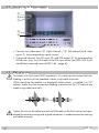
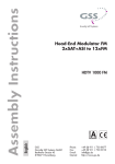
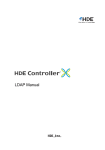
Head-End Station STC 160 4 x Digital MPEG2 Encoder HDE 164 English Notes on the Assembly Instructions. As well as this supplementary Assembly Instructions, the Assembly Instructions for the STC 160 apply. GSS Grundig SAT Systems GmbH Beuthener Strasse 43 D-90471 Nuremberg Phone: Fax: E-mail: Internet: +49 (0) 911 / 703 8877 +49 (0) 911 / 703 9210 [email protected] http://www.gss.de/en Contents 1 Safety regulations........................................................................................ 3 2 General information..................................................................................... 4 2.1 Scope of delivery...........................................................................4 2.2 Meaning of the symbols used...........................................................4 2.3 Technical data................................................................................4 2.4 Description....................................................................................6 3 Installation................................................................................................... 7 3.1 Installing the Encoder module...........................................................8 3.2 Connecting the Encoder module.......................................................9 3.3 EMC regulations.............................................................................9 4 The control panel at a glance...................................................................... 10 4.1 Functions of the control panel buttons..............................................10 4.2 Menu items..................................................................................10 5 Programming............................................................................................. 11 5.1 Programming procedure................................................................11 5.2 Programming the module...............................................................13 Selecting the module / channel strip...............................................13 Output parameter.........................................................................14 ASI transfer rate......................................................................14 ASI options.............................................................................15 Input parameter............................................................................16 Data rate of the video signal.....................................................16 TV standard............................................................................17 Aspect ratio............................................................................17 Sharpness...............................................................................17 Audio signal type and bit rate...................................................18 Level of the audio signal...........................................................18 Programme number (SID - Service ID).........................................19 Channel name........................................................................19 ASI Input station filter....................................................................20 Transport stream ID and ORGNET ID..............................................22 Factory reset................................................................................22 Saving settings ............................................................................23 6 Final procedures......................................................................................... 23 - 2 - HDE 164 1 Safety regulations • The standards EN/DIN EN 50083 resp. IEC/EN/DIN EN 60728 must be observed. • Do not perform installation and service work during thunderstorms. • Assembly, installation and servicing should be carried out by authorised electricians. • Switch off the operating voltage of the system before beginning with assembly or service work. • Avoid short circuits! • Observe the relevant standards, regulations and guidelines on the installation and operation of antenna systems. • To ensure electromagnetic compatibility, make sure all connections are tight and the covers are screwed on securely. • No liability is accepted for damage caused by faulty connections or inappropriate handling of the device. Check the head-end station according to the safety instructions listed in their assembly instruction. Take precautions to prevent static discharge when working on the device! Electronic devices should never be disposed of in the household rubbish. In accordance with directive 2002/96/EC of the European Parliament and the European Council from January 27, 2003 which addresses old electronic and electrical devices, such devices must be disposed of at a designated collection facility. At the end of its service life, please take your device to one of these public collection facilities for proper disposal. - 3 - HDE 164 2 General 2.1 S c o p e o f d e l i v e ry 1 Module HDE 164 1 BNC cable 1 Brief assembly instructions 2.2 M e a n i n g o f t h e s ym b o l s u s e d —> – – / / • 2.3 T e c h n i c a l information Important note General note Optional use of the buttons Performing works data The devices meet the following EU directives: 2006/95/EC, 2004/108/EC The product fulfils the guidelines and standards for CE labelling (page 24). Unless otherwise noted all values are specified as "typical". CVBS Video Inputs: Standard:......................................................................DIN EN 50049-1 Input level:...................................................................................... 1 Vpp Input impedance:............................................................................. 75 Ω Frequency range:........................................................... 20 Hz … 5 MHz Audio Inputs: Standard:......................................................................DIN EN 50049-1 Input level:...............................................................................500 mVrms Input impedance:........................................................................... 10 kΩ Frequency range:...........................................................20 Hz … 15 kHz MPEG2 Encoder: Transport stream:............................................. MPEG2 (ISO/IEC 13818-1) Video data stream:.......................................... MPEG2 (ISO/IEC 13818-2) Audio data stream:.......................................... MPEG1 (ISO/IEC 11172-3) Output data rate:...................................................... 2 Mbit/s…15 Mbit/s Audio data rate:....................................................... 192 kb/s…384 kb/s - 4 - HDE 164 ASI Interfaces Standard:......................................................................DIN EN 50083-9 Format:...............................................................MPEG ISO IEC 13818-1 Max. data rate....................................................................... 108 Mbit/s User data rate:..................................................................2 … 90 Mbit/s Impedance:..................................................................................... 75 Ω Level (input / output):......................................................800 mVpp ± 10% Rise/Fall Time:............................................................. < 1.2 ns (20-80%) Reflexion loss (input):...........................................> 17 dB (5 … 270 MHz) Connections: Audio inputs: .............................................................4 x 2 Cinch sockets CVBS Video inputs: . ....................................................... 4 Cinch sockets, ASI input:..................................................................1 BNC socket, 75 Ω ASI output:.................................................................1 BNC socket, 75 Ω Connection strip (20-pin):..................... for supply voltages and control circuit Remote maintenance Remotely controllable (via PSW 160*):................................................. yes (* and a corresponding management unit) - 5 - HDE 164 2.4 D e s c r i p t i o n AV 1 R Audio-Eingang Audio input Cinch Video-Eingang Video input Cinch FBAS CVBS AV 2 R L Audio-Eingang Audio input Cinch Video-Eingang Video input Cinch FBAS CVBS AV 3 R L Audio-Eingang Audio input Cinch Video-Eingang Video input Cinch FBAS CVBS AV 4 R Audio-Eingang Audio input Cinch Video-Eingang Video input Cinch L L FBAS CVBS ASI-Eingang ASI input BNC µP / TPS-MODUL In the module HDE 164 four analogue audio and video signals are converted into MPEG2 data streams (transport streams). The transport streams are emitted via the ASI output. ENCODER ASI-Ausgang ASI output BNC The module is equipped with four video/stereo audio inputs and one ASI data stream input. The fed in analogues signals are digitized and supplied to an encoder that encodes them in real time. The stereo audio signals are transferred via an adjustable amplifier to the encoder. The bit rates are adjustable. A transport stream fed via the ASI input socket will be inserted into the transport streams of the encoded analogous signals. In this way it is possible to connect several HDE 164 in series. IN OUT - 6 - HDE 164 At the ASI output sockets (BNC) a transport stream is provided according to ISO/IEC 13818-1. When the head-end station is switched on, the two-line LC display shows the "SETUP" menu and the software version of the control unit. The control of the module takes place via the control unit of the head-end station. To operate the encoder module the software version of the control unit (head-end station) must be "V 10" or higher. The operating software of the encoder module and the head-end station can be updated using a PC and the software "BE-Flash" via the 9-pin D-SUB socket on the head-end station. You can find the current operating software for the head-end station and the encoder module, the software "BE-Flash" and the current assembly instructions on the website "www.gss.de/en". The encoder module is designed exclusively for use in the STC 160 head-end station. 3 Installation – Ensure the head-end station is mounted so it will not be able to vibrate. Avoid, for example, mounting the head-end station onto a lift shaft or any other wall or floor construction that vibrates in a similar way. – Before installing or changing a module, switch off the head-end station or unplug the power cable from the mains power socket. – Take measures to protect against ESD! • Open the housing of the head-end station in accordance with the assembly instructions for the STC 160. - 7 - HDE 164 3.1 I n s ta l l i n g t h e E n c o d e r m o d u l e – When installing a module, make sure that it is inserted in one of the long, numbered grooves in front of the contact strip on the board at the rear wall of the housing. – The shorter, non-numbered grooves without a contact strip on the board at the rear wall of the housing are for add-on modules only. • Open the housing of the head-end station in accordance with the assembly instructions for the STC 160. • Open the locking device A in the direction of the green arrow. A • Insert the Encoder module in grooves B of an open slot (with contact strip on the board at the rear wall of the housing) and gently slide it into the head-end station until it makes contact with the board on the rear wall. • After installing the Encoder module close the locking device A in the direction of the red arrow. —> Ensure that the ground spring C gets contact to the locking device. B C A B - 8 - HDE 164 3.2 C o n n e c t i n g t h e E n c o d e r m o d u l e D E F G H • Connect the audio inputs D (right channel) / E (left channel) and video inputs F to corresponding signal sources. • If required connect the ASI input G and ASI output H to corresponding ASI devices (e.g. the ASI output to the ASI input of the next HDE 164 if you would like to cascade several HDE 164 ; page 6). 3.3 EMC r e g u l at i o n s To comply with the current EMC regulations, it is necessary to connect the lines leading in and out of the head-end station using cable terminals. When mounting the module in a head-end station which is installed in a 19" cabinet, make sure the connections leading in and out for the 19" cabinet are made using cable terminals. Tighten the nuts on the cable terminals until the teeth on the lock washer have penetrated the exterior coating and a good connection is made between the housing and cable terminals. - 9 - HDE 164 4 The control panel at a glance 4.1 F u n c t i o n s o f t h e c o n t r o l pa n e l b u t to n s M S 4.2 M e n u items Program the Encoder module using the buttons on the head-end station control panel. The menus appear on the two-line display of the control panel. The parameters and functions to be set are underlined. With the button select the channel strip / other modules. You can use the button to select the following menu items: – – – – – – To move the cursor To adjust values and functions To save the programmed data To switch to the next menu ASI output settings ASI data rate ASI options Input settings Bit rate Standard Aspect ratio Sharpness Audio data rate Volume Station number Station name Station Filter (ASI input) Transport stream and ORGNET-ID Factory reset Save data - 10 - HDE 164 5 Programming 5.1 Progr a mming Ein/On SETUP procedure BE160 V 10 Bx 1 ……… ……… ……… Bedienhinweise "blättert" Menüs vorwärts. M wählen die Eingabeposition / wählt Untermenü stellen Werte ein,. / S speichert alle Eingaben. 1 zeigt die Eingabeposition Operating Hints scrolls forward through the menu. M select the enter position. / selects a submenu. set values and triggers actions. / S saves all entries. 1 shows the enter position A page 12 Bx 2 ASI 4xENCODER V1 / Bx 3 ……… ……… ……… > 2 sec. = abbrechen / cancel Bx 2 ASI OUTPUT => Bx 2 Bx 2 Bx 2 INPUT AV 1 => ASI RATE 108000 KBits 1…180 MBits ASI OPTION 188 pos. cont. AV 1…4 BITRATE 10.0 Mbps /204 /neg. /burst /Audio only/2…15/off AV 1…4 AV 1…4 NORM PAL BG 4.43 MHz AV 1…4 ASPECT 4:3 AV 1…4 SHARPNESS normal AV 1…4 Stereo VOLUME 0 dB /16:9 /sharp/soft AUDIO 256 kbps AV 1…4 /PAL N 3.58 MHz - 11 - /Joint/Dual/Mono L /256/320/384 -11…+11 HDE 164 Stereo 256 kbps AV 1…4 /Joint/Dual/Mono L /256/320/384 VOLUME -11…+11 0 dB AV 1…4 PRG-NUM 1…255 ! 00001 ! = Programmnummer ist bereits belegt ! = Programme number is already in use AV 1…4 NAME PROG 1 Bx 2 INPUT Bx 2 ASI OK => all FILTER all manual nur bei Einstellung "manual" Only with setting "manual" BX 2 TV + Services entfernen / hinzufügen Removing / activating services 01/04 Das Erste Bx 2 nächster Service (Programm) next service (station) TS/ONID 0x0001,0100 M Bx 2 FACTORY Defaults => Werkeinstellung aufrufen invoke factory defaults M Bx 2 Bx 2 FACTORY STORE => S S A page 11 M MEMORY S => STORE Einstellung speichern S store factory defaults STORE A page 11 M CANCEL A page 11 - 12 - HDE 164 5.2 P r o g r a m m i n g the module Notes: – Entries are saved by pressing the button. —> You will be returned to "Selecting the module/channel strip". – The programming process can be cancelled by pressing and holding the button. —> Changes will NOT be saved. —> You will be returned to "Selecting the module/channel strip". • Switch on the head-end station. —> The display shows "SETUP BE160" and the software version of the head-end station (e.g. V 10). —> The output level of the output collector can be adjusted in the "SETUP" menu (see STC 160 assembly instructions). Ein / On Selecting • If necessary, press to be programmed. the module ……… Bx 2 ASI / SETUP BE160 V 10 channel strip repeatedly to select the particular module (Bx …) ……… 4xENCODER V1 / Bx 3 ……… ……… ……… —> The display shows e.g. the menu Bx 2 4xENCODER ASI V 1. "Bx 2" stands for slot 2 "4xENCODER" type of module "V 1" software version of the module - 13 - HDE 164 • Press the button. —> The "Output parameter" – "OUTPUT" main menu is activated. Output In this menu you get access to the output parameter submenus. pa r a m e t e r Bx 2 OUTPUT ASI => —> If you do not want to do output settings, press the button. The "Input parameter" – "INPUT" main menu is activated (page 16). • Press the button. —> The "ASI transfer rate" – "ASI RATE" submenu is activated. ASI t r a n s f e r In this menu you set the transfer rate for the ASI component connected (incl. stuffing - filled up user data rate). For this setting please take the required information from the documentation (technical data) of the ASI component to be connected. r at e Bx 2 ASI RATE 108000 KBits • Use the use the • Press the buttons to select the digits to be set for the transfer rate then buttons to set the transfer rate wished. button. —> The "ASI options" – "ASI OPTION" submenu is activated. - 14 - HDE 164 ASI o p t i o n s In this menu you define the size of the data packets, their polarity and the type of transmission. For this setting please take the required information from the documentation (technical data) of the ASI component to be connected. Bx 2 ASI OPTION 188 pos. cont. • Press the bits). buttons to set the size of the data packets ("188" or "204" • If the polarity of the data to be transmitted has to be changed, press the to select "pos." (positive – standard) and using the buttons set to "neg." (negative). • To change the type of transmission press the buttons to select "cont." (continuous – standard) and using the buttons set to "burst". —> Setting "cont." The data packets of the user data are spaced out evenly in the transport stream. —> Setting "burst" The data packets of the user data are collected to a great data packet in the transport stream. • Press the button. —> Return to the main menu "Output parameter" • Press the button. —> The "Input parameter" – "INPUT" main menu is activated. - 15 - HDE 164 Input In this menu you select the input, you would like to set the input parameters in the submenus (AV 1 … AV 4). pa r a m e t e r Bx 2 INPUT AV 1 => —> If you do not want to do input settings, press the button. The "ASI station filter" – "INPUT ASI" main menu is activated (page 20) • Using the • Press the buttons select the corresponding input. button. —> The "Data rate of the video signal " – "BITRATE" submenu is activated. D ata You can use this menu to set the data rate at which the video signal is to be encoded. The higher the data rate, the higher the quality of the transmitted video signal. r at e o f t h e v i d e o s i g n a l AV 1…4 BITRATE 10.0 Mbps • Use the buttons to set the data rate of the video signal ("2.0" … "15.0" Mbit/sec). If only audio signals are to be encoded, set the data rate to "Audio only". In setting "Off" the input is switched off. • Press the button. —> The "TV standard" – "NORM" submenu is activated. - 16 - HDE 164 TV s ta n da r d In this menu the TV standard of the input signal is to be set - "PAL BG 4.43 MHz" or "PAL N 3.58 MHz". • Use the • Press the AV 1…4 NORM PAL BG 4.43 MHz buttons to set the TV standard wished. button. —> The "Aspect ratio" – "ASPECT" submenu is activated. Aspect In this menu the aspect ratio of the input signal is to be set - "16:9" or "4:3". r at i o AV 1…4 ASPECT 4:3 • Use the • Press the buttons to set the aspect ratio wished. button. —> The "Sharpness" – "SHARPNESS" submenu is activated. Sharpness In this menu the you set the sharpness wished - "normal", "sharp" or "soft". AV 1…4 SHARPNESS normal • Use the • Press the buttons to set the sharpness wished. button. —> The "Audio signal type and bit rate" – "Audio" submenu is activated. - 17 - HDE 164 Audio In this menu you set the signal type and the bit rate the audio signal is to be encoded. s i g n a l t y p e a n d b i t r at e AV 1…4 Stereo AUDIO 256 kbps • Use the buttons to set the signal type – "Stereo", "Joint Stereo" (subjectively improved stereo impression), "Dual Channel" (dual channel sound) or "Mono L" (left) - of the audio signal. • Use the button to select the bit rate setting and set it as wished with the buttons ("192" … "384" kbit/sec). The higher the bit rate, the higher the quality of the transmitted audio signal. Bear in mind that when the bit rate is increased, the bandwidth of the output signal is also increased. • Press the button. —> The "Level of the audio signal" –"VOLUME" submenu is activated. Level In this menu you can adapt the volume of this audio input. o f t h e au d i o s i g n a l AV 1…4 VOLUME 0 dB • Use the • Press the buttons to set the desired volume ("– 11dB" … "+ 11dB"). button. —> The "Programme number" –"PRG-NUM" submenu is activated. - 18 - HDE 164 Progr a mme In this menu you can set the Service ID of the input. number (SID - S e rv i c e ID) AV 1…4 PRG-NUM 00001 • Use the buttons to set the Service ID wished ("1" … "255"). —> A "!" behind the Service ID indicates that this ID is already in use by another input. Using several HDE 164 (cascading see page 6) don´t assign the same SID twice. • Press the button. —> The "Channel name" – "NAME" submenu is activated. Channel In this menu the channel name of the input can be set. name AV 1…4 NAME PROG 1 • Use the buttons to select the digit of the channel name to be set and use buttons to set the desired character (" ", "0…9", "A…Z", "Ä", "Ö", "Ü", "a…z", "ä", "ö", "ü", "+", "-", "/", ":" or "*"). • Press the button. —> Return to the main menu "Input parameter" • Use the buttons to select the 2nd AV input and carry out its settings analogous to that of the 1st AV input, or • Press the button. —> The "ASI Input station filter" – "INPUT" main menu is activated. - 19 - HDE 164 ASI I n p u t Herein you get access to the submenus for ASI input filter settings. s tat i o n f i lt e r Bx 2 INPUT ASI OK => —> If no ASI input filter settings should be done, press button . The "TS ID and ORGNET ID" – "TS/ONID" main menu is activated (page 22) —> If no ASI input signal is present, "– –" is displayed instead of "OK". • Press the Bx 2 INPUT ASI – – => button. Bx 2 FILTER all Using buttons you can select, whether all services (all) or only selected services (manual) are passed through. • Activate the filter function by selecting "manual". • Press the button. —> All services from the ASI input will be read, and then displayed with name and type of the service.. —> If no services is found, the following message will appear in the display: "no Service". In this case, check previously adjusted settings for the module and the components connected to the ASI input. —> The display shows e.g.: Bx 2 TV + 01/04 Das Erste - 20 - HDE 164 Meaning of the indicators in the example: "TV" "Television" (type of service) " + " The currently selected service is passed through "01/04" The 1st of 4 services is being displayed. "Das Erste" Name of the service Further possible terms displayed: "RA" "Radio" (type of service) For radio stations, the background of the screen of the connected TV or test receiver is darkened. "–" The currently selected service is blocked. " * " The star means that the service selected is scrambled. —> If a service number (e.g. "131") appears instead of "TV" or "RA", this indicates that an unnamed service or an undefined transport stream is being received. • Use the buttons to call up the services in sequential order, then use buttons to pass through (indicated by " + ") or to block them (" – "). —> If the filter function is activated (setting "manual"), only services which are marked by "+" will be passed. If the services at the ASI input are changed, new services (which are not marked by "+") will be blocked. • Press the button. —> Return to the main menu "ASI input station filter" • Press the button. —> The "Transport stream ID and ORGNET ID" – "TS/ONID" main menu is activated. - 21 - HDE 164 Tr a n s p o r t s t r e a m ID a n d ORGNET ID If the input signals are encoded to a separate transport stream (e.g. setting of the output signal path -> ASI without any ASI input signal), a new ORGNET-ID must be assigned to the transport stream. Bx 2 TS/ONID 0x0001,0100 • Use the use the buttons to select the digit of the hexadecimal number to be set and buttons to set the desired character. • Press the button. —> The "Factory reset" – "FACTORY Defaults" main menu is activated. Fac to ry In this menu you can reset all settings to the factory defaults. reset Bx 2 FACTORY Defaults Bx 2 => STORE M • Press the FACTORY => S S M button. —> The factory defaults are invoked ("FACTORY STORE"). —> By pressing the button, you will be returned to the main menu "Selecting the module" (page 13). • Press the button. —> The factory defaults are saved. The display shows "STORE" —> Back to "Selecting the module" (page 13). - 22 - HDE 164 S av i n g s e t t i n gs Bx 2 MEMORY S => STORE S STORE M CANCEL • All programmed data is saved by pressing the button. —> The settings are saved. —> Return to "Selecting the module / channel strip" (page 13). —> By pressing the button, you will be returned to the menu item "Selecting the module / channel strip" without saving the programmed data. 6 Final procedures After installing the head-end station, upgrading accessories or installing modules it is necessary to tighten all cable connections, cable terminals and cover screws in order to maintain compliance with current EMC regulations securely. • Mount the base plate and the front cover (see STC 160 assembly instructions). - 23 - HDE 164 Declaration of CE conformity Service: Phone: +49 (0) 911 / 703 2221 • Fax: +49 (0) 911 / 703 2326 • Email: [email protected] Grundig SAT Systems GmbH • Beuthener Straße 43 • D-90471 Nürnberg Alterations reserved. Technical data E. & O.E. © by GSS GmbH V1/04122012