1
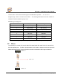
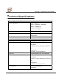
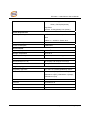
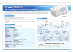
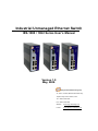
Industrial Unmanaged Ethernet Switch IES-1080 / 1062 Series User’s Manual Version 1.0 May, 2008. ORing Industrial Networking Corp. 4F., NO.3, Lane235, Baociao Rd.Sindian City, Taipei County 23145 Taiwan, R.O.C. Tel: + 886 2 2918 3036 Fax:+ 886 2 2918 3084 Website : www.oring-networking.com E-mail : [email protected] Table of Content Getting to Know Your Switch................................................................................... 1 1.1 About the IES-1080 / 1062 unmanaged Industrial Switch........................................................... 1 1.2 Hardware Features ........................................................................................................................... 1 Hardware Installation ............................................................................................... 2 2.1 2.1.1 2.2 2.2.1 Installation Switch on DIN-Rail ........................................................................................................ 2 Mount IES-1080 / 1062 series on DIN-Rail.................................................................................... 2 Wall Mounting Installation ................................................................................................................ 3 Mount IES-1080 / 1062 series on wall ............................................................................................ 3 Hardware Overview .................................................................................................. 6 3.1 Front Panel......................................................................................................................................... 6 3.2 Front Panel LEDs .............................................................................................................................11 3.3 Bottom Panel ....................................................................................................................................11 3.4 Rear Panel ....................................................................................................................................... 12 Cables...................................................................................................................... 13 4.1 4.1.1 4.2 Ethernet Cables............................................................................................................................... 13 100BASE-TX/10BASE-T Pin Assignments ................................................................................. 13 Fibers ................................................................................................................................................ 14 Technical Specifications ........................................................................................ 15 IES-1080 / 1062 Series User’s Manual Getting to Know Your Switch 1.1 About the IES-1080 / 1062 unmanaged Industrial Switch The IES-1080 / 1062 series are reliable unmanaged industrial switches which can work under wide temperature, dusty environment and humid condition. 1.2 Hardware Features 10/100/1000Base-T(X) Gigabit Ethernet port 10/100Base-T(X) Ethernet port 100Base-FX Fiber port 1000Base-X Fiber port Redundant three DC power inputs (two on terminal block & one on power jack) Casing: IP-30 Dimensions(W x D x H) : 52 mm(W)x 106 mm( D )x 144 mm(H) Operating Temperature: -40 to 70oC Storage Temperature: -40 to 85oC Operating Humidity: 5% to 95%, non-condensing ORing Industrial Networking Corp. 1 IES-1080 / 1062 Series User’s Manual Hardware Installation 2.1 Installation Switch on DIN-Rail Each switch has a DIN-Rail kit on rear panel. The DIN-Rail kit helps switch to fix on the DIN-Rail. It is easy to install the switch on the DIN-Rail: 2.1.1 Mount IES-1080 / 1062 series on DIN-Rail Step 1: Slant the switch and mount the metal spring to DIN-Rail. Metal Spring 2 ORing Industrial Networking Corp. IES-1080 / 1062 Series User’s Manual Step 2: Push the switch toward the DIN-Rail until you heard a “click” sound. 2.2 Wall Mounting Installation Each switch has another installation method for users to fix the switch. A wall mount panel can be found in the package. The following steps show how to mount the switch on the wall: 2.2.1 Mount IES-1080 / 1062 series on wall ORing Industrial Networking Corp. 3 IES-1080 / 1062 Series User’s Manual Step 1: Remove DIN-Rail kit. Step 2: Use 6 screws that can be found in the package to combine the wall mount panel. Just like the picture shows below: 4 ORing Industrial Networking Corp. IES-1080 / 1062 Series User’s Manual The screws specification shows in the following two pictures. In order to prevent switches from any damage, the screws should not larger than the size that used in the switches. Pozidrive Step 3: Mount the combined switch on the wall. ORing Industrial Networking Corp. 5 IES-1080 / 1062 Series User’s Manual Hardware Overview 3.1 Front Panel The following table describes the labels that stick on the IES-1080 / 1062 series. Port Description 10/100Base-T(X) RJ-45 fast Ethernet ports support auto-negotiation. 10/100 RJ-45 fast Default Setting : Ethernet ports Speed: auto Duplex: auto Gigabit port 2 1000 BASE-T Giga ports.(IES-1062GT) 1000BaseX for IES-1062GF-MM, IES-1062GF-SS Fiber port 6 100BaseFX for IES-1062FX-MM, IES-1062FX-SS ORing Industrial Networking Corp. IES-1080 / 1062 Series User’s Manual IES-1080 1. LED for PWR. When the Power on, the green led will be light on. 2. LED for PWR1. When the PWR1 links, the green led will be light on. 3. LED for PWR2. When the PWR2 links, the green led will be light on. 4. LED for Fault Relay. When the power fault occurs, the amber LED will be light on. 5. 10/100Base-T(X) Ethernet ports. 6. LED for Ethernet ports status. 7. Model name 8. 10/100Base-T(X) Ethernet ports 9. LED for Ethernet ports status. ORing Industrial Networking Corp. 7 IES-1080 / 1062 Series User’s Manual IES-1062FX (Single-mode, multi-mode) 1. LED for PWR. When the Power on, the green led will be light on. 2. LED for PWR1. When the PWR1 links, the green led will be light on. 3. LED for PWR2. When the PWR2 links, the green led will be light on. 4. LED for Fault Relay. When the power fault occurs, the amber LED will be light on. 5. 10/100Base-T(X) Ethernet ports.. 6. LED for Ethernet ports status. 7. Model name 8. 100BaseFX fiber port. 9. LED for fiber port. 8 ORing Industrial Networking Corp. IES-1080 / 1062 Series User’s Manual IES-1062GT 1. LED for PWR. When the Power on, the green led will be light on. 2. LED for PWR1. When the PWR1 links, the green led will be light on. 3. LED for PWR2. When the PWR2 links, the green led will be light on. 4. LED for Fault Relay. When the power fault occurs, the amber LED will be light on. 5. 10/100Base-T(X) Ethernet ports.. 6. LED for Ethernet ports status. 7. Model name 8. 1000Base-T Ethernet port. 9. LED for gigabits Ethernet port. ORing Industrial Networking Corp. 9 IES-1080 / 1062 Series User’s Manual IES-1062GF (Single-mode, multi-mode) 1. LED for PWR. When the Power on, the green led will be light on. 2. LED for PWR1. When the PWR1 links, the green led will be light on. 3. LED for PWR2. When the PWR2 links, the green led will be light on. 4. LED for Fault Relay. When the fault occurs, the amber LED will be light on. 5. 10/100Base-T(X) Ethernet ports.. 6. LED for Ethernet ports status. 7. Model name 8. 1000BaseX gigabits Fiber port. 9. LED for gigabits Fiber port. 10 ORing Industrial Networking Corp. IES-1080 / 1062 Series User’s Manual 3.2 Front Panel LEDs LED Color Status Description PWR Green On DC power connected PWR1 Green On DC power module 1 activated. PWR2 Green On DC power module 2 activated. Fault Amber On Fault relay. Power failure or Port down/fail. 10/100Base-T(X) Fast Ethernet ports LNK / ACT Duplex Green Amber On Port link up. Blinking Data transmitted. On Port works under full duplex. Gigabit Ethernet ports / Fiber ports LNK Amber On Port link up. ACT Green Blinking Data transmitted. 3.3 Bottom Panel The bottom panel components of IES-1080 / 1062 series are shown as below: 1. Terminal block includes: PWR1, PWR2 (12-48V DC) and Relay output (1A@24VDC). 2. Power jack for PWR3 (12-45VDC). PWR1, PWR2 (12-48V DC) and Relay output (1A@24VDC). Power jack for PWR3 (12-45VDC) . ORing Industrial Networking Corp. 11 IES-1080 / 1062 Series User’s Manual 3.4 Rear Panel The rear panel components of IES-1080 / 1062 Series are showed as below: 1. Screw holes for wall mount kit. 2. DIN-Rail kit 12 ORing Industrial Networking Corp. IES-1080 / 1062 Series User’s Manual Cables 4.1 Ethernet Cables The IES-1080 / 1062 series switches have standard Ethernet ports. According to the link type, the switches use CAT 3, 4, 5,5e UTP cables to connect to any other network device (PCs, servers, switches, routers, or hubs). Please refer to the following table for cable specifications. Cable Types and Specifications Cable Type Max. Length Connector 10BASE-T Cat. 3, 4, 5 UTP 100 m (328 ft) RJ-45 100BASE-TX Cat. 5 100-ohm UTP UTP 100 m (328 ft) RJ-45 1000BASE-TX Cat. 5/Cat. 5e 100-ohm UTP UTP 100 m (328ft) RJ-45 100-ohm 4.1.1 100BASE-TX/10BASE-T Pin Assignments With 100BASE-TX/10BASE-T cable, pins 1 and 2 are used for transmitting data, and pins 3 and 6 are used for receiving data. RJ-45 Pin Assignments Pin Number Assignment 1 TD+ 2 TD- 3 RD+ 4 Not used 5 Not used 6 RD- 7 Not used 8 Not used ORing Industrial Networking Corp. 13 IES-1080 / 1062 Series User’s Manual The IES-1080 / 1062 series switches support auto MDI/MDI-X operation. You can use a straight-through cable to connect PC and switch. The following table below shows the 10BASE-T/ 100BASE-TX MDI and MDI-X port pin outs. MDI/MDI-X pins assignment Pin Number MDI port MDI-X port 1 TD+(transmit) RD+(receive) 2 TD-(transmit) RD-(receive) 3 RD+(receive) TD+(transmit) 4 Not used Not used 5 Not used Not used 6 RD-(receive) TD-(transmit) 7 Not used Not used 8 Not used Not used Note: “+” and “-” signs represent the polarity of the wires that make up each wire pair. 4.2 Fibers The following four models, IES-1062FX-MM, IES-1062GF-MM, IES-1062FX-SS, IES-1062 GF-SS, have fiber optical ports. The fiber optical ports are in multi-mode or single-mode with SC connector. Please remember that the TX port of Switch A should be connected to the RX port of Switch B. Switch A TX RX Fiber cord RX TX Switch B 14 ORing Industrial Networking Corp. IES-1080 / 1062 Series User’s Manual Technical Specifications Technology Ethernet Standards 802.3 - 10BaseT, 802.3u - 100BaseTX, 100BaseFX, 802.3z - 1000BaseLX 802.3ab - 1000BaseTX, 802.3x - Flow Control MAC addresses 8192 Flow Control IEEE 802.3x Flow Control and Back-pressure Processing Store-and-Forward Interface RJ45 Ports 10/100Base-T(X), Auto MDI/MDI-X Giga Fiber Ports 1000 Base-X (SC Connector) Multi-Mode: 0 to 550m, 850 nm (50/125 µm to 62.5/125 µm) Single-Mode: 0 to 10km, 1310 nm (9/125 µm) Giga Ports 10/100/1000 Base-T(X), Auto MDI/MDIX Fiber Ports 100 Base-FX (SC Connector) Multi-Mode: 0 to 2 km, 1310 nm (50/125 µm to 62.5/125 µm) Single-Mode: 0 to 30km, 1310 nm (9/125 µm) LED Indicators Per Unit : Power(Green) RJ45 Ports: ORing Industrial Networking Corp. 15 IES-1080 / 1062 Series User’s Manual Per Port : Link/Activity(Green/Blinking Green), Full duplex(Amber) Giga Ports: Per Port : Activity(Green),Link (Amber) Power Requirements Power Input Voltage PWR1/2: 12 ~ 48VDC in 7-pin Terminal Block PWR3: 12 ~ 45VDC in Power Jack Reverse Polarity Protection Present at terminal block Power Consumption 8 Watts Max Environmental Operating Temperature -40 to 70oC Storage Temperature -40 to 85oC Operating Humidity 5% to 95%, non-condensing Mechanical Dimensions(W x D x H) 52 mm(W)x 106 mm(D)x 144 mm(H) Casing IP-30 protection Regulatory Approvals Regulatory Approvals FCC Part 15, CISPER (EN55022) class A EMS EN61000-4-2 (ESD), EN61000-4-3 (RS), EN61000-4-4 (EFT), EN61000-4-5 (Surge),, EN61000-4-6 (CS) Shock IEC 60068-2-27 Free Fall IEC 60068-2-32 Vibration IEC 60068-2-6 Warranty 5 years 16 ORing Industrial Networking Corp.