1
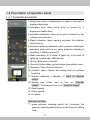
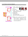
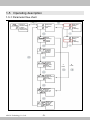
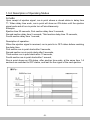
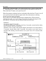
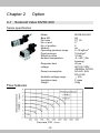
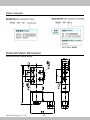
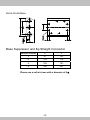
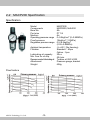
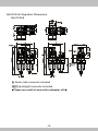
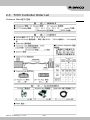
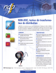
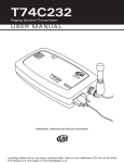
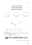
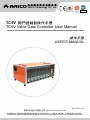
長新科技股份有限公司
ARICO Technology Co., Ltd.
Registered to
ISO 9001
TC5V 閥門控制器操作手冊
TC5V Valve Gate Controller User Manual
操作手冊
USER'S MANUAL
Ver.:TC5V-1.0.2
長新科技股份有限公司
ARICO Technology Co., Ltd.
保有權利於任何時間未經通知而修改或變更本手冊內容及型式,未經本公司同意,不得作任何形式的使用。
reserves the right to make any kind of design or functional modification at any moment without prior notice.
For avoid wrong operation to make human injured or machine damage,
Please read this instruction carefully before use the instrument.
CONTENT
Chapter 1
TC5V Valve Gate Controller Module
1-1
Features
1
1-2
Specification Software function
1
1-3
Module specification
1
1-4
Description of operation panel
2
1-5
Operation Flow
5
Chapter 2
Option
2-1
Solenoid Valve MVSE-260
10
2-2
MACP200 Specification
13
2-3
TC5V Controller Order List
15
-2-
Chapter 1
1-1
■
■
■
■
■
■
■
■
1-2
■
■
■
■
■
■
TC5V Valve Gate Controller
Module
Feature
Multiple Touch-off signal options(AC220/110/DC24/Switch type)
Multiple output voltage options (AC220/110/DC24/Relay/MOS Relay)
Time display is adjustable to the first digit after the decimal point
Stopwatch can be either accumulative or countdown.
Three optional control modes.
Optional pressure retaining mode.
MOS Relay extension of working life.
Mechanical Relay(up to 600mA) is optional.
Specification Software function (setting level)
A, B, AB three control switches
Pressure retaining mode switch (delay, work)
Pressure retaining delay time setting
Pressure retaining time setting
Decimal point switch
Display mode
1-3 Module specification
■
■
■
■
■
Panel measurement: 50*176mm
Display: 7-Section tube 0.4*4*2
Power switch: Manual dial type
Input power: AC220 (50/60Hz)
Trigger voltage: (Must jump JP), AC110 (50/60Hz), AC220 (50/60Hz), DC24,
Switch (DC24)
■ Output power: (must jump JP), AC110(RELAY/electronic switch 4VA), AC220
(RELAY,2A/electronic switch 600mA),DC24 (RELAY/electronic
switch 4W), RELAY-2A/electronic switch-600mA (either one)
■ Keys: 5 keys (select/confirm, manual output, plus, minus, time setting)
■ Function display lamps: A/B mode lamp, OPEN lamp, SIGNAL lamp,
pressure retaining lamp, manual output lamp
ARICO Technology Co., Ltd.
-1-
1-4 Description of operation panel
1-4-1 Faceplate description
1. Delay time: when a transmission is signal is received, it
displays delay time.
2. Activation time: when run-in point is turned on, it
displays activation time.
3. Activation indication: when run-in point is turned on, the
indicator lamp turns on.
4. Signal indication: when signal is received, the indicator
lamp turns on.
5. Pressure retaining indication: when pressure retaining is
activated, lamp will turn on; when pressure retaining is
operating, it flashes on and off.
6. Mode indication: In A mode, A lights up; in B mode, B
lights up; in AB mode, A&B light up.
7. Up key: Sets plus or function.
8. Time set: Enters delay and activation time setting mode.
9. Down key: Sets minus or function.
10. Function option: Enters the setting level for optional
functions
11. Manual indication: Indication of start of manual
output
12. Manual key: Press once to turn on, “manual
output”;Press again to turn off, “manual output”.
13. Panel handle
14. Power switch
15. Fix panel
Fast key function:
”T” press pressure retaining switch for 3 seconds, the
pressure retaining switch will save the previous setting
time.
-2-
1-4-2 Interior structural diagram
1
5
2
6
7
3
4
ARICO Technology Co., Ltd.
1. Jumper signal input selection
short-circuit method
2. Fuse
3. Work Relay
4. Output selection Jumper short-circuit
method same as first point
5. AC220V input
6. AC220V/110V/
DC24V/Relay output
7. Signal input and grounding wire end
Caution: when you select short-circuit PIN,
please be careful in regards to the shortcircuit direction, up-and-down shortcircuit is the correct direction, and each
set can only select one.
-3-
1-4-3 Faceplate appearance and dimension
Deviation:±5mm
-4-
1-5
Operating description
1-5-1 Parameter flow chart
Range of
manual output
0~999.9
Display only,
cannot be set
Delay time
activation
time
Delay time
setting
range
0~999.9(s)
Mode
switching
options:
A/B/AB
Action time
setting
range
0~999.9(s)
Pressure
retaining
function:
ON/OFF
Pressure
retaining
delay time,
range
0~19.9(s)
Pressure
retaining time,
range
0~19.9(s)
Decimal
point:
YES: On
NO: Off
Display time
mode: UP:
up count
DOWN:
down count
ARICO Technology Co., Ltd.
-5-
A
mode
B
mode
1-5-2 Description of Operating Modes
A mode
Upon receipt of ejection signal, run-in point shows a closed status in delay time
T1. When delay time ends, run-in point will show an ON status until the ejection
signal ends and all run-in points turn off simultaneously.
Example:
Ejection time 20 seconds, First section delay time 3 seconds,
Second section delay time 5 seconds, Third section delay time 10 seconds,
Fourth section delay time 1 second,
Description of operation:
When the ejection signal is received, run-in point is in OFF status before reaching
the delay time.
First section run-in point starts after 3 seconds,
Second section run-in point starts after 5 seconds,
Third section run-in point starts after 10 seconds,
Fourth section run-in point starts after 1 second,
Run-in point shows an ON status, after ejection time ends, at the same time 1-4
sections are switched to OFF status, and wait for the signal of the next ejection.
-6-
B mode
Upon receipt of ejection signal, run-in point shows an OFF status in delay time
T1. When delay time T1 ends, run-in point shows an ON status in start time T2.
When start time T2 ends, run-in point turns off.
When the pressure retaining function is activated, after start time T2 ends, turn off
run-in point and wait until ejection signal ends, then start pressure retaining
function and stop receiving signals.
Run-in point is in ON status during pressure retaining time. When pressure
retaining time ends, run-in point turns off and starts to wait for the signal of the
next ejection. All sections can set different delay and start times.
Example 1:
Set ejection signal 10 seconds
First section delay time 3 seconds, start time 4 seconds; second section delay
time 4 seconds, start time 6 seconds
Operation: Upon receipt of the ejection signal, first section run-in point starts in
3 seconds; second starts after 4 seconds, first section run-in point turns 4
seconds after starting, second section run-in point turns off 6 seconds after
starting.
ARICO Technology Co., Ltd.
-7-
Example 2 (with pressure retaining function)
Set ejection signal 10 seconds
First section delay time 3 seconds, start time 4 seconds, pressure retaining
start time 3 seconds
Second section delay time 4 seconds, start time 6 seconds, pressure retaining
start time 3 seconds
Operation: After ejection signal is received, first section run-in point starts in 3
seconds; second sections starts in 4 seconds, first section run-in point turns off
4 seconds after starting, second section run-in point turns off 6 seconds after
starting, after all section run-in points turn off, wait for the end of ejection
signal, enter pressure retaining operation to start run-in point turn off 3
seconds, and begin to receive signals of the next ejection.
-8-
AB mode(applicable to trigger
mechanical switches)
signal models with exterior
Upon receipt of the ejection signal, run-in point shows OFF status in delay time
T1. When delay time T1 ends, run-in point shows ON status in start time T2.
When start time T2 ends, run-in point turns off.
When pressure retaining time setting is activated, after start time T2 ends, run-in
point shows OFF status in pressure retaining time, when pressure retaining delay
time ends, run-in point shows ON status in pressure retaining time; when
pressure retaining time ends, run-in point turns off.
Example:
Set ejection signal 12 seconds
First section delay time 3 seconds, start time 4 seconds, pressure retaining delay
time 3 seconds, pressure retaining time 2 seconds; second section delay time 4
seconds, start time 6 seconds, pressure retaining delay time 0 seconds, pressure
retaining operation time 2 seconds
Operation:
Upon receipt of ejection signal, first section run-in point starts after 3 seconds,
and closes after 4 seconds after run-in point starts, and enters pressure retaining
mode after run-in point is closed, run-in point starts after delay 3 seconds, and
closes after 2 seconds after run-in point starts. Second section run-in point starts
4 seconds after receipt of signal, run-in point closes 6 seconds after starting and
enters pressure retaining mode, run-in point starts 0 seconds after it is closed,
run-in point closes 2 seconds after the start.
ARICO Technology Co., Ltd.
-9-
Chapter 2
2-1
Option
Solenoid Valve MVSE-260
Series specification
Model
Bore NO.
Port size
No. of port
No. of position
Medium
Operating pressure range
Proof pressure
Effective orifice
Ambient temperature
Response time
voltage
Power consumption
Available voltage range
Insulation class
Weight
Flow features
-10-
MVSE-260-4E1
8A
PT 1/4
5口
2
Air
2~12 kgf/cm2
15 kgf/cm2
18 mm2
-5~+50℃(No
freezing)
40 ms
AC110V, 220V
(50/60)Hz, DC24V
AC=6/4, 9VA,
DC=2.5W
±10%
F class
255g
Order example
Solenoid Valve Dimension
MVSA-220-5B Valve Body
ARICO Technology Co., Ltd.
-11-
MVSA-220-5B Base
Base Suppressor and 8φ Straight Connector
Manifold number
P
L
2
57
69
4
103
115
6
149
161
8
195
207
Please use a soft air hose with a diameter of 8φ.
-12-
2-2
MACP200 Specification
Specification
Model
Components
Bore No.
Port size
Medium
Operating pressure range
Proof pressure
Regulation pressure range
Ambient temperature
Filtration
Lubricating oil capacity
Min. flow for oil drip
Recommended lubricating oil
Attachment
Weight
Flow feature
ARICO Technology Co., Ltd.
-13-
MACP200
MAFR200, MAL200
8A
PT 1/4
Air
0~9.9kgf/cm2 (0~0.99MPa)
15kgf/cm2 (1.5MPa)
0.5~8.5kgf/cm2
(0.05~0.85MPa)
-5~+60℃(No freezing)
Standard:40μm
Option:5μm
25c.c
50l/min
Turbine oil ISO-VG32
Pressure gauge, bracket
606g
MACP200 Air Regulator Dimensions
MACP200-B
IN Quick male connector included
OUT 8φ straight connector included
*Please use a soft air hose with a diameter of 8φ.
-14-
2-3
TC5V Controller Order List
Customer Name客戶名稱:
ARICO Technology Co., Ltd.
-15-
長新科技股份有限公司
ARICO Technology Co., Ltd.
總公司(HEADQUARTERS)
23145新北市新店區寶橋路235巷1弄1號8樓
8F., No.1, Alley. 1, Lane 235, Baociao Rd., Sindian District, New Taipei City, 23145, Taiwan
TEL:+886-2-29101266
FAX:+886-2-29159434
www.arico.tw -31/ www.arico.com.tw
ARICO Technology Co., Ltd.