1
Revision 2c – 6 Dec 2012
NewCode Relay
Page 1 of 41
NewCode Relay
User Manual
Revision 2c
6th December 2012
NewElec (Pty) Ltd
Head Office
c/o Soutter & Maltzan Street
Pretoria-West
Gauteng
South-Africa
Revision 2c – 6 Dec 2012
NewCode Relay
Page 2 of 41
CONTENT
Page
1.
ABSTRACT
3
2.
SPECIFICATIONS
4
3.
DEFINITIONS AND TERMINOLOGY
11
4.
FUNCTIONAL DESCRIPTION
13
5.
INSTALLATION INSTRUCTIONS
16
5.1
5.2
Front-end requirements
Setting up procedure
6.
DIAGRAMS:
6.1.1
6.1.2
6.2
6.3
6.3.1
6.3.2
6.3.3
6.3.4
6.3.5
6.4
6.4.1
6.4.2
6.4.3
6.4.3
6.4.4
6.4.5
6.4.6
6.4.7
6.4.8
6.4.9
6.5
6.6
6.7
6.8
6.9
6.10
Picture of the relay
Physical layout of the relay
Block diagram of the relay
Front-End Setup Screens
Settings Screen
Control Logic Screen
Starter Logic Screen
Statistics and Network Screen
Real Time Clock Screen
Front-End Assistance Screens
Test Screen (Manual)
Test Screen (Automatic)
Test Screen (Automatic)
Spectrum Analyzer Screen (square wave)
Spectrum Analyzer Screen (sine wave)
Actual Screen
Calculator Screen
Fault Screen
Event Screen
Recorder Screen
Thermal Curves of the Relay
Mechanical Outline of the Relay
Electrical diagram of the Relay
Expanded I/O module of the Relay
RTD Module Wiring Diagram
4mA to 20mA Module Wiring Diagram
7.
ACCESSORIES
38
Revision 2c – 6 Dec 2012
NewCode Relay
Page 3 of 41
1.
Abstract
The NewCode Relay is an ISO 9001:2000 compliant, local designed and manufactured three
phase motor protection relay. It is a micro-controller based precision instrument with protection,
advanced control features and starter logic. The relay is designed to cater for the low voltage
motor protection market and is available in different current models. The current transformers,
including the core balance current transformers are external.
The relay is fully configurable with the aid of front-end software or a man machine interface unit
(MMI). Event records can also be downloaded with the aid of the MMI onto a memory stick for
further analysis. All the settings are password protected. The relay has an on board database
where time and date stamped records are kept. Two types of records are kept namely fault
records (35 last faults) and event records (1400 events). In the case of event records, the user has
limited access rights (read only). The front-end also has a data recorder and a spectrum analyzer
which could be used to analyze motor performance and supplied power quality respectively.
The spectrum analyzer can detect harmonics up to the 9th harmonic on any of the three phase
currents.
The relay detects earth leakage currents with the aid of the external core balance currenttransformer and is configurable to operate in inverse definite minimum time (IDMT) or
instantaneous definite time (IDT) mode.
A unique feature is added to the relay in the form of simulation. This function could be used for
personnel training or relay functionality testing.
Revision 2c – 6 Dec 2012
NewCode Relay
Page 4 of 41
2.
Specifications
2.1
Measurements
2.1.1
Current
• Three phase current
• Range: 5 Amp to 400 Amps (5A to 400A with additional external CTs)
• Models: 5, 10, 25, 50, 100, 200 and 400.
• Sensitivity range adjustment (MLC): 10% to 100% of full load current
• Dynamic range: 0% to 1000%
• Resolution: 500 steps (2% per step)
2.1.2 Voltage
• Range: 110V, 400V, 525V, 550V, 1050V, 3k3V, 6k6V and 11kV (from 3k3V
upwards a step down transformer is used to step the voltage down to 110V).
• Range selection: Manual
2.1.2
Frequency
• Range: 30Hz to 100Hz
• Selectable during calibration: 50Hz or 60Hz (factory setting)
2.1.3
Power Factor
• Range: 0 to 100% (leading / lagging)
2.1.4
Power Dissipation
• Type: Apparent power (kVA) and Real power (kWatt);
• Derived from line voltage, phase current and power factor (where applicable)
2.1.5 Earth Leakage
• Range: 30mA to 3 Amps
• Trip time delay: Inverse Definite Minimum Time (IDMT) or Instantaneous
Definite Time (IDT)
2.1.6
Real Time Clock
• 24 hour clock (Year, month, date, hours and minutes)
• Battery backup (5 days with 1 Farad super capacitor)
• Time and date stamping (Fault and event records)
2.1.7 Breaker Fault Clearance Time
• Measurement range: 10 ms to 1000ms
• Resolution: 10ms steps.
Revision 2c – 6 Dec 2012
NewCode Relay
Page 5 of 41
2.1.8 Insulation Resistance
• Measurement range: 1 to 199 kOhm
• Resolution: 1 kOhm steps.
2.2
Protection Features
(All resets are subjected to sufficient thermal capacity gain)
2.2.1 Over Current (Overload) Detection
• Curve class settings: 3 seconds to 40 seconds
• IEC 60255-8 specification
• Motor full load setting (MLC): 10% to 100%
• Reset: Manual or three automatic resets per hour (when selected)
• Reset threshold setting: Fixed at 70% thermal capacity or dynamic threshold
adjustment determined over 10 last restarts.
2.2.2
Undercurrent (Minimum load) Detection
• Trip level adjustment: 10% to 100%
• Selection: Current level or power factor %
• Trip delay time: 1 to 10 seconds
• Start-up delay: 1 to 200 seconds (To facilitate pump priming)
• Reset time: Manual or 10 seconds to 6 hours (9 steps)
• Feature selectable
2.2.3 Unbalance Phase Currents Detection
• Trip level adjustment: 0 to 50%
• Trip delay time: 1 to 10 seconds
• Reset: Manual
• Feature selectable
2.2.4
•
•
•
Single Phasing (Phase lost) Detection
Trip delay time: 1 second fixed
Feature selectable
Reset: Manual
2.2.5 Run-Stall Detection
• Stall current trip level adjustment: 110% to 300%
• Stall trip delay time: 0 to 120 seconds adjustable
• Feature selectable
• Reset: Manual
Revision 2c – 6 Dec 2012
NewCode Relay
Page 6 of 41
2.2.6
Vectorial-Stall Detection
• Trip: Static or decreasing power factor
• Trip delay: 33% of curve class setting.
• Reset: Manual
• Feature selectable
2.2.7
Starts per Hour Control
• Starts setting: 1 to 60 starts adjustable
• Consecutive starts: 1 to 3 starts per interval adjustable
• Reset: Automatic
• Feature selectable
2.2.8 Short Circuit Detection
• Articulated detection: If (ILOAD > 950% and Power factor < 85%) or
(ILOAD > 300% and Power factor > 85%)
• Trip delay time: 1 second fixed
• Reset: Manual
• Feature selectable
2.2.9 Voltage Symmetry Detection
• Trip delay time: 10 seconds fixed
• Trip level adjustment: 70% to 99%
• Reset: Manual
• Feature selectable
2.2.10 Over Voltage Detection
• Trip delay time: 10 seconds fixed
• Trip level: Factory settings
• Reset: Manual
• Feature selectable
2.2.11
2.2.12
•
•
•
•
Under Voltage Detection
Trip delay time: 10 seconds fixed
Trip level: Factory settings
Feature selectable
Reset: Manual
High or Low Frequency Detection
• Trip delay time: 10 seconds fixed
• Trip level: Factory settings (45Hz to 55Hz)
• Reset: Manual
• Feature selectable
Revision 2c – 6 Dec 2012
NewCode Relay
Page 7 of 41
2.2.13 Voltage Phase Rotation
• No trip delay time
• Auto reset once fault is fixed
• Feature selectable (forward, reverse, none)
2.2.14 Insulation Failure Detection
• Detection: Only in static state (motor not running)
• Trip delay time: 1 second fixed
• Trip level: Resistance < 20 kOhm (fixed)
• Reset: Manual
• Feature selectable
2.2.15 Earth Leakage Detection ( IEL < 2A)
• Selection between Instantaneous Definite Time or Inverse Definite Minimum
Time.
• Instantaneous Definite Time (100 ms ≥ t ≥ 1000 ms), (50 ms steps)
• Inverse Define Minimum Time ( t ≥ 130 ms)
• Harmonic filtering (suitable for variable speed drives and soft starters)
• Trip level: Adjustable
• Reset: Manual
• Feature selectable
2.2.16 Earth Fault Detection ( IEL ≥2A)
• Harmonic filtering (suitable for variable speed drives and soft starters)
• Trip delay time: 1 second fixed
• Trip level: 2A fixed
• Reset: Manual
• Feature selectable
Revision 2c – 6 Dec 2012
NewCode Relay
Page 8 of 41
2.3
Control logic
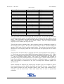
2.3.1
Table of control outputs which can be mapped to any configurable input.
Input
Input
Input
Input
Input
Input
Zero ('0')
OverVolt_af
MinLoad_tf
RTClock
! LogicFunc_4
PLC_Input_2
One ('1')
UnderVolt_af
OverVolt_tf
! RTClock
LogicFunc_5
PLC_Input_3
InService
VoltSym_af
UnderVolt_tf
Counter_A
! LogicFunc_5
PLC_Input_4
VoltPresentF
HiFreq_af
VoltSym_tf
! Counter_A
LogicFunc_6
PLC_Input_5
OverCrnt_af
LoFreq_af
HiFreq_tf
Counter_B
! LogicFunc_6
PLC_Input_6
ShortCirc_af
IsoLockOut_af
LoFreq_tf
! Counter_B
DigFldInput_1
PLC_Input_7
RunStall_af
OverCrnt_tf
IsoLockOut_tf
LogicFunc_1
DigFldInput_2
PLC_Input_8
I_Unbal_af
ShortCirc_tf
PhaseRot_tf
! LogicFunc_1
DigFldInput_3
StarterOutp_1
I_Unbal_af
RunStall_tf
StartsPerHr_tf
LogicFunc_2
DigFldInput_4
StarterOutp_2
SinglePhs_af
I_Unbal_tf
Timer_A
! LogicFunc_2
DigFldInput_5
StarterOutp_3
EarthFault_af
SinglePhase_tf
! Timer_A
LogicFunc_3
DigFldInput_6
Restart
EarthLeak_af
EarthFault_tf
Timer_B
! LogicFunc_3
DigFldInput_7
FrozenContact
MinLoad_af
EarthLeak_tf
! Timer_B
LogicFunc_4
PLC_Input_1
TripFlag
2.3.2 Timers
• Timer A and Timer B
• Time setting: 0 to 50 minutes
• Start input: Configurable and level triggered (see 2.3.1)
• Reset / Inhibit input: Configurable and level triggered (see 2.3.1)
2.3.3 Real Time Clock (24 Hour)
• Start time: Hours and minutes configurable (see 2.3.1)
• Stop time: Hours and minutes configurable (see 2.3.1)
2.3.4
Counters
• Counter A and Counter B
• Count range: 0 to 250
• Count up input: Configurable and positive edge triggered (see 2.3.1)
• Count down input: Configurable and positive edge triggered (see 2.3.2)
• Reset / Inhibit input: Configurable and level triggered (see 2.3.1)
• Trip level setting: 1 to 250 counts
2.3.5 Logic function blocks
• Amount of function blocks: 6
• Three fully configurable inputs per logic function block (see 2.3.1).
• Sum of product or product of sums operation
Revision 2c – 6 Dec 2012
NewCode Relay
Page 9 of 41
2.3.6
Starter Logic
• Starter types:
1. Direct On Line Starter
2. Reversible Direct On Line Starter
3. Star-Delta Starter
4. Reversible Star-Delta Starter
5. Dahlander Starter
6. Reversible Dahlander Starter
7. Soft Starter.
8. Reversible Soft Starter
9. Pulsed Output Direct On Line Starter
• Timers:
1. Star Maximum Timer: 1 to 50sec
2. Pre Start Warning Timer: 1 to 1200 sec (20 min)
3. Execution Timer: 1 to 10 sec (Start executing)
4. Feedback Timer: 50ms to 2000ms (Power dips)
5. Unautherised Current Timer: 50ms to 2000ms
6. Backspin Timer: 1 to 600 sec
7. Transition Timer: 50ms to 5000ms (Change over from high speed to low speed)
• Selectable control sites: Local, remote, automatic (PLC control) and operator pannel
2.3.7 Relays
• Amount of Relays: 4
• Input: Configurable and level triggered (see 2.3.1)
• Slow relay 1 / Fast main trip relay selectable.
• Single set of potential free switch-over contacts
2.3.8
Pulse Generator
• Period: 1 to 250 min
• Duty cycle: 1 to 99%
• Control / Reset input
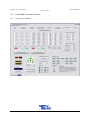
2.4
Statistical Data Capturing
•
•
•
•
•
Running hours: Adjustable (0 to 65535 hours)
Startup counter: Adjustable (0 to 65535)
Trip counter: Adjustable (0 to 65535)
Apparent power consumption metering (kV.A.h)
Real power consumption metering (kWatt.h)
Revision 2c – 6 Dec 2012
NewCode Relay
Page 10 of 41
2.5
Trip Fault Recording
2.5.1
Database capacity: 35 last faults
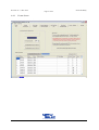
2.5.2 Trip fault record content:
• Status: (Actual / simulated)
• Date: Year, month, date
• Time: Hour, minute
• Fault description
• Run hours
• Max trip current
• Minimum trip voltage
• Breaker fault clearance time.
2.6
Event Recording
2.6.1 Database capacity: 1400 last events
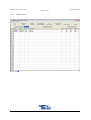
2.6.2 Event record content:
• Status: Actual, Simulated, Settings adjust, Power up, Calibration
• Date: Year, month, date
• Alarm flags
• Trip flags
• Run hours
• Max trip current
• Min trip voltage
• Breaker fault clearance time
• Digital field input states
2.7
Physical dimensions
2.8
Auxiliary power supply
• Size of foot print: 45 mm x 110 mm (DIN Rail mount / screw fix mount)
• Length: 110 mm
• Mass: 400 gram
•
•
Voltage requirements: 110 Vac ± 10% or 230 Vac ± 10%
Power requirements: 2,5 Watt
Revision 2c – 6 Dec 2012
NewCode Relay
Page 11 of 41
2.9
•
•
Operating environment
Temperature: 0 – 50° Celsius
Relative humidity: < 85
2.10 Networking (Communication)
2.10.1 Protocol:
• Profibus
• ModBus
• Canbus
Revision 2c – 6 Dec 2012
NewCode Relay
Page 12 of 41
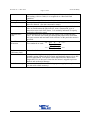
3.
Definitions and Terminology
Apparent power
consumption
Apparent power
dissipation
Breaker clearance
time
Consecutive starts
Core balance
current transformer
Digital field input
Earth fault
Earth leakage fault
Full load current
Fundamental harmonic frequency
In Service state
Isolation lockout /
Insulation failure
Motor full load
setting (MLC)
Non volatile
memory
Over current
(Overload)
Phase rotation
It is the amount of energy consumed. The power factor is not taken into
account and is measured in kV.A.h
It is the product of voltage and current. The power is excluded and it is
measured in kV.A
It is the time taken by the breaker to clear the fault by interrupting the
supply current to the motor. It can be seen as breaker response time and
is useful information for breaker maintenance.
The amount of starts allowed during a time interval created by the starts
per hour setting. (See also starts per hour)
A current transformer used to detected possible current leakage to earth
from one or more of the phases. (Earth leakage detection)
A signal generated by an external switch that could have an effect on the
relay operation depending on the logic configuration.
It is leakage current above 2 amps and a severe form of an earth leakage
condition. (See also core balance current transformer)
It is leakage current up to 2 amps exceeding a trip level setting. (See also
core balance current transformer)
Current drawn by the motor at full load operation (90% to 100%)
50Hz in South Africa and 60Hz elsewhere.
Phase current above 10% of full load current
The insulation resistance of the motor is measured while in a static (not
in service) condition. If the resistance drops below 20 kOhm the relay
will trip and will prevent a start.
Adjustment of the relay current sensitivity. This is where the current
level measurement is adjusted to read just below 100% when the motor
operate at full load.
It is memory that will maintain data even when power is switched off for
long periods. (see also volatile memory)
Current level above 100% of full load current
Real power
consumption
Real power
dissipation
Normal phase rotation sequence is red, white and blue. Reverse rotation
sequence is blue, white and red.
It is die relationship between real power and apparent power
Power factor % = ((V x I x CosØ) / (V x I)) x 100%
Power factor = CosØ
It is the amount of energy consumed. The power factor is taken into
account and is measured in kWatt.h
It is the product of voltage and current. The power factor is included and
it is measured kWatt.
Run-Stall
The motor went through the normal start procedure and the current level
Power factor
Revision 2c – 6 Dec 2012
NewCode Relay
Page 13 of 41
Running hours
Starts per hour
Thermal capacity
Thermal curve
class
Total Harmonic
Distortion
Undercurrent
(Minimum load)
Vectorial-Stall
Volatile memory
return to normal full level. If the rotor jam and the current rise above the
stall setting (110% to 300%) it is recognized as a Run-Stall fault
condition.
The amount of time the motor was in an in-service state.
Starts per hour define the time interval in which a restricted amount of
starts are allowed. (See also consecutive starts)
It is a temperature related quantity expressed in percentage, which also
takes in consideration the physical size, mass, construction, type of
material etcetera used of the motor. It is normally indicated as capacity
used unless otherwise stated.
It is the thermal curve derived from the unitary (one second) thermal
curve. It is also the curve that goes through the points where maximum
lock rotor current and maximum lock rotor time of the particular motor is
specified.
H + H + .... H × 100 %
Two standards are used: THD =
H
2
2
2
+
H 1 H 2 + .... H n × 100 %
THD =
H 1 + H 2 + .... H n
Current level when motor run at no load condition.
2
2
2
1
2
n
1
It is detected during the startup procedure of the motor. A motor
normally startup with a bad power factor and gradually improve it as full
speed is approached. If no power factor improvement is detected for
longer then 33% of the curve class time the motor is tripped to prevent
thermal and mechanical damage.
It is memory that will loose data during a power supply interruption.
(see also non volatile memory)
Revision 2c – 6 Dec 2012
NewCode Relay
Page 14 of 41
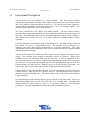
4.
Functional Description
The NewCode relay is controlled by a micro-controller. The three phase currents,
voltages and earth leakage current are detected by current transformers, attenuator circuits
and a core balance current transformer respectively. The current and voltage signals are
conditioned by appropriate circuits and converted to 0 to 5 volt analogue signals. The
analogue signals are digitized to 10 bit resolution.
The micro-controller has non volatile and volatile memory. The non volatile memory
contains a boot loader program which is used to upload the operating software program of
the relay. The uploading is done from a personal computer or laptop via the USB port.
This feature also enables the user to do future software upgrades without factory
assistance.
Front-end software is included that runs on MS Windows™. The USB port and infra red
link (IrDA) are used as communication ports. The purpose of the front-end is to
configure and select the required functionality of a specific application. The setup
adjustments required at the installation phase will be discussed in the next chapter dealing
with installation instructions.
The relay will monitor the parameters of the motor for the duration of auxiliary power
supply. The auxiliary power supply is selectable (110Vac or 230Vac). When a trip
condition occurs, the main trip relay will be activated. It will be energized or deenergized (non fail save or fail save respectively) depending on what mode of operation
was selected. A time and date stamped trip record is also generated and saved in non
volatile memory for later retrieval. Memory space for 60 trip records is allocated. The
layout of the trip record is discussed in chapter 2 that deals with specifications.
Event records are also time and date stamped. It is more comprehensive and saved in non
volatile memory. Only read access is given to the user. This information can be used for
insurance claims and liability cases. The layout of the event record is discussed in chapter
2 (specifications).
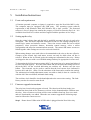
Six fault indication light emitting diodes (red) are placed on the front panel. The green
light emitting diode will come on only if the relay is in a healthy state. A healthy state
signifies that the motor could be static or in operation within it’s save operating
parameters. The fault indications are displayed on the front panel as follows:
Revision 2c – 6 Dec 2012
NewCode Relay
Page 15 of 41
Name of Fault
Over current
Short circuit
Minimum load
Phase Rotation
Unbalance Phase Currents
Single Phasing
Insulation Failure
Run-Stall
Vectorial-Stall
Earth leakage
Earth fault
Over voltage
Under voltage
Voltage symmetry
Starts per hour
High frequency
Low frequency
Indication LED used
Overload
Overload
Min Load
Phase Rotation
Unbalance
Unbalance
Insulation failure
Overload
Overload
Earth leakage
Earth leakage
Phase rotation
Phase rotation
Phase rotation
Overload & Healthy
Unbalance
Unbalance
Display mode
Solid on
Solid on
Solid on
Solid on
Solid on
Solid on
Solid on
Solid on
Solid on
Solid on
Solid on
3 sec on, 1 sec off
1 sec on, 3 sec off
1 sec on, 1 sec off
Both 1 sec on, 1 sec off
3 sec on, 1 sec off
1 sec on, 3 sec off
The reset button is used to acknowledge and reset trip faults. A reset will only take affect
if sufficient thermal capacity is regained during the cooling period and no phase current
flows. If the reset button is pressed during the cooling cycle the Overload LED will start
flashing (1 second on, 1 second off) to signify cooling. Once the required thermal
capacity level is reached, the relay will reset.
The real time clock is running from a super capacitor which is continuously charged by
the auxiliary power supply. The real time clock should be able to continue running for
another 5 days in the event of auxiliary supply failure. The real time clock provides time
and date for record keeping (fault and event records) and also participates in the control
functions.
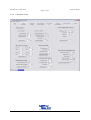
The protection unit (NewCode) is equipped with four electromechanical relays (Relay 1,
2, 3 and 4) and seven opto-isolated digital field inputs (Digital Field Inputs 1 to 7). When
Relay 1 is configured as the main trip relay it has a dedicated protection function. Relay
2, 3 and 4 are general purpose relays. The relays are configurable and available to
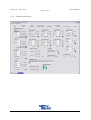
participate in any of the control functions. The control logic is realized with the aid of six
logic function blocks. Each of these blocks has three configurable inputs. A configurable
input can typically be connected to any one of seventy three different signals (see
specifications).
Starter functions are added to the control logic and three types are available to choose
from namely Direct On Line (DOL), Star-Delta and Forward / Reverse. Three different
start control localities are also selectable namely local, remote and automatic (PLC
control) to start the motor from. These start control sites are static or dynamically
selectable.
Revision 2c – 6 Dec 2012
NewCode Relay
Page 16 of 41
The protection unit (NewCode) has an internal interchangeable communication module.
Three different protocols are available and to choose from namely Modbus, Profibus and
CANbus.
Revision 2c – 6 Dec 2012
NewCode Relay
Page 17 of 41
5.
Installation Instructions
5.1
Front-end requirements
A Pentium personal computer or laptop is required to setup the NewCode MK-1 relay.
The computer must be equipped with USB ports. The operating system software
requirement is MS Windows 2000, MS Windows XP or later versions. The front-end
software is free of charge but remains the property of NewElec Pretoria (Pty) Ltd. It is
available from NewElec's website and also supplied with the purchase of new relays.
5.2
Setting up the relay
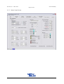
Once the wiring is being done and checked by qualified personnel, the relay is ready to be
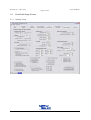
configured. The four most important front-end screens are the settings (diagram 6.4),
control logic, starter and statistics screens. These four screens enable the user to adjust
parameters, select protection features, determine control strategy, select a starter
configuration and setup the communications network. The control and starter screens are
linked together when settings are saved or retrieved from disk.
When setting changes were made it has to be transmitted to the relay to become effective.
Changes on the control logic and starter screens can only be made when off line is
selected. When on line is selected again, the settings are transmitted to the relay. Relays
are shipped to the user with a set of default settings and may be appropriate in some cases.
To determine the full load current setting (MLC), the motor has to be started and allowed
to run at full load capacity. Press the reset button and use the front-end settings screen to
adjust the MLC till the overload indication just switches off. Release now the reset
button. The front-end can be used to confirm that the load current level indicated is
between 90% and 99%. (Hint: Use the calculator of the front-end to confirm the setting).
The minimum load setting adjustment (motor run with no load) is done in a similar way
with the aid if the reset button, minimum load setting.
The real time clock should be checked and adjusted to the correct time setting. The fault
history can also be erased to start afresh.
5.3
Firmware upgrade instructions
The relay has a boot loader program on board. The function of the boot loader is to
facilitate the down load of new firmware revisions via the frontend and the USB bus onto
the relay. Newer firmware revisions will be come available when bug fixes were made
and new functionality was added. When the user wants to upgrade the following steps
must be followed to ensure success.
Step 1 - Ensure that a USB to mini-b USB cable is plugged into the NewCode relay.
Revision 2c – 6 Dec 2012
NewCode Relay
Page 18 of 41
Step 2 - Power up the relay (either 110V or 220V AC) as per Electrical wiring diagram.
Step 3 - Launch the NewCode boot loader software Ver 1A from the CD provided.
Step 4 - Select the correct Communication Port from the drop down list. Once selected
click “OPEN PORT”
Step 5 - The “COMPORT OPENED” message will be displayed in the Session message
box. Click on “SEARCH FOR DEVICE” Tab (Top Left RED Button). The
‘UNBALANCE’, ‘OVERLOAD’ and ‘INSULATION FAILURE’ LED’s will light up.
Step 6 - “Looking for Device” will be displayed in the Session Message Box. “Device
Found”, will be displayed in the Session Message Box. “Version: xx.xx”, will be
displayed in the Session Message Box. “Product ID :x”, will be displayed in the Session
Message Box. The ‘UNBALANCE’, ‘OVERLOAD’ and ‘INSULATION FAILURE’
LED’s will light up.
Step 7 - Click on “OPEN UPDATE FILE” (Second button from the left). Select the latest
NewCode .enc file (example NC_ENC_1D-00.enc) Click on “OPEN”. The
‘UNBALANCE’, ‘OVERLOAD’ and ‘INSULATION FAILURE’ LED’s will light up.
Step 8 - The Bootloader will now check the integrity of the selected file. “Status: Busy
Checking Open File xx%” will be displayed in the bottom left corner of the Bootloader.
This should take approximately 45 seconds (PC dependant). The ‘UNBALANCE’,
‘OVERLOAD’ and ‘INSULATION FAILURE’ LED’s will light up.
Step 9 - Once the file has been checked and no faults found, “File Loaded: ‘File
Location’” will be displayed in the Session Message Box. The “UPLOAD FILE TO
RELAY” Button will now be active (Third button from the left) Click on “UPLOAD
FILE TO RELAY’ Button.
Step 10 - The Bootloader will erase the files currently stored in the Flash Memory on the
relay and will automatically begin uploading the new firmware to the flash. This step
may take approximately 5 minutes to complete. During the Erase Cycle, the
‘UNBALANCE’, ‘OVERLOAD’, ‘PHASE ROTATION’ and ‘ EARTH LEAKAGE’
LED’s will light up. During the Programme Cycle the ‘MIN LOAD’, ‘PHASE
ROTATION’ and ‘EARTH LEAKAGE’ LED’s will light up. During both cycles, the
progress is displayed as a % in the bottom left of the Bootloader
Step 11 – Once the Programming is complete, the relay should automatically be returned
to its normal mode and the GREEN LED indicating ‘RELAY HEALTHY’ will light up.
The Bootloader can now be closed and the NewCode Frontend must be re-opened.
Revision 2c – 6 Dec 2012
NewCode Relay
Page 19 of 41
6.
Diagrams
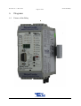
6.1
Picture of the Relay
Revision 2c – 6 Dec 2012
NewCode Relay
Page 20 of 41
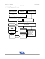
6.2
Block Diagram of the Relay
Current Transformers
Core Balance Current
Transformer
Voltage Signal
Conditioning Circuits
Current Signal Conditioning Circuits
Real Time Clock
Fault & Status
Indication LEDs
Relays
Relay 1 - 4
Reset
Switch
Analogue to Digital
Converters
Data Processor
Volatile Memory
* Temporary data
Digital Field
Inputs
Serial Port
RS232
I2C
Communication
Module
Non Volatile Memory
* Relay settings
* Fault Records
* Event Records
* Boot loader
* Program code
Revision 2c – 6 Dec 2012
NewCode Relay
Page 21 of 41
6.3
Front-End Setup Screens
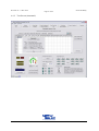
6.3.1
Settings screen
Revision 2c – 6 Dec 2012
NewCode Relay
Page 22 of 41
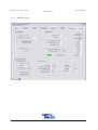
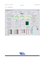
6.3.2
Control Logic Screen
Revision 2c – 6 Dec 2012
NewCode Relay
Page 23 of 41
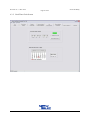
6.3.3
Starter Logic Screen
Revision 2c – 6 Dec 2012
NewCode Relay
Page 24 of 41
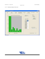
6.3.3
Statistics Screen
Revision 2c – 6 Dec 2012
NewCode Relay
Page 25 of 41
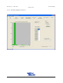
6.3.5
Real Time Clock Screen
Revision 2c – 6 Dec 2012
NewCode Relay
Page 26 of 41
6.4
Front-End Assistance Screens
6.4.1
Test Screen (Manual)
Revision 2c – 6 Dec 2012
NewCode Relay
Page 27 of 41
6.4.2
Test Screen (Automatic)
Revision 2c – 6 Dec 2012
NewCode Relay
Page 28 of 41
6.4.3
Spectrum Analyzer Screen (1)
Revision 2c – 6 Dec 2012
NewCode Relay
Page 29 of 41
6.4.4
Spectrum Analyser Screen (2)
Revision 2c – 6 Dec 2012
NewCode Relay
Page 30 of 41
6.4.5 Actual Screen
Revision 2c – 6 Dec 2012
NewCode Relay
Page 31 of 41
6.4.6
Calculator Screen
Revision 2c – 6 Dec 2012
NewCode Relay
Page 32 of 41
6.4.7
Fault Screen
Revision 2c – 6 Dec 2012
NewCode Relay
Page 33 of 41
6.4.8
Events Screen
Revision 2c – 6 Dec 2012
NewCode Relay
Page 34 of 41
6.4.9
Recorder Screen
Revision 2c – 6 Dec 2012
NewCode Relay
Page 35 of 41
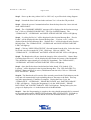
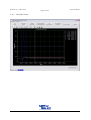
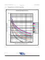
6.5
Thermal Curves of the NewCode Relay
NewCode Thermal Trip Curve
10000
Trip Time Delay ( Seconds )
1000
Class 40
Class 35
Class 30
Class 25
Class 20
100
Class 15
Class 10
Class 5
Class 3
Class 1
10
1
1
2
3
4
5
6
7
8
Muiltipiles of Full Load Current Setting
9
10
Revision 2c – 6 Dec 2012
NewCode Relay
Page 36 of 41
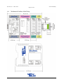
6.6
Mechanical Outline of the Relay
Revision 2c – 6 Dec 2012
NewCode Relay
Page 37 of 41
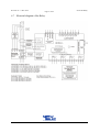
6.7 Electrical diagram of the Relay.
Revision 2c – 6 Dec 2012
NewCode Relay
Page 38 of 41
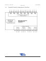
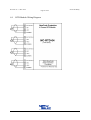
6.8
Expanded IO module wiring diagram of the Relay.
Revision 2c – 6 Dec 2012
NewCode Relay
Page 39 of 41
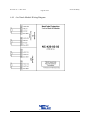
6.9
RTD Module Wiring Diagram
Revision 2c – 6 Dec 2012
NewCode Relay
Page 40 of 41
6.10 4 to 20mA Module Wiring Diagram
Revision 2c – 6 Dec 2012
NewCode Relay
Page 41 of 41
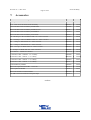
7.
Accessories
NewElec NewCode Ordering Information
Description.
Part No
Bin No.
110 – 230V NewCode Motor Protection Relay
FPR0416
65660
NewCode Motor Protection Relay with Profibus
FPR0400
65661
NewCode Motor Protection Relay with DeviceNet
FPR0417
65662
NewCode Motor Protection Relay with Modbus
FPR0418
65663
NewCode Motor Protection Relay with Canbus
FPR0419
65664
30 - 300 Amp C.T. & Core Balance with 110 – 550V Converter
FPR0401
65670
10 – 100 Amp C.T. & Core Balance with 110 – 550V Converter
FPR0402
65671
0.1 – 1 Amp C.T. Block with 110 – 550V Converter
FPR0403
65675
0.5 – 5 Amp C.T. Block with 110 – 550V Converter
FPR0404
65676
0.25 – 25 Amp C.T. Block with 110 – 550V Converter
FPR0405
65677
5 – 50 Amp C.T. Block with 110 – 550V Converter
FPR0406
65678
Core Balance - 100mm Dia. Window
BTX0010
65679
Connection Cable – 1000mm – C.T. to Relay
FPR0408
65685
Connection Cable – 500mm – C.T. to Relay
FPR0409
65686
Connection Cable – 300mm – C.T. to Relay
FPR0410
65687
Connection Cable – 100mm – C.T. to Relay
FPR0411
65688
External Memory Module
FPR0407
65695
NewCode Expanded I/O Module – 8 In/4 Out
FPR0412
65696
RTD Expansion Module
FPR0413
65697
NewCode Insulation Lockout Module
FPR0420
65698
NC-MK1-420-02-02 2X40-20 mA Input/Output
FPR0414
--oo0oo--