1
KX-MMI-420-EP
Page 1 / 21
KD/KE-Relay Man Machine
Interface
4x20 Display
(Explosion Proof)
User Manual
KE-MMI-420-EP
Version 01.01
(NE_KX-MMI-420_MAN_01_10_FN01)
14 June 2010
NewElec Pretoria (Pty) Ltd
Head Office: c/o 298 Soutter street & Maltzan street
Pretoria West
South-Africa
0182
GPS: 25°45'12''S 28°09'46''E
Http://www.newelec.co.za
KX-MMI-420-EP
Page 2 / 21
CONTENT
Page
3
1.
ABSTRACT
2.
2.1
2.2
2.3
2.4
2.5
SPECIFICATIONS
Electrical Requirements of the MMI
Mechanical Properties of the MMI
Communication Link of the MMI
Menu structure with Unit of the MMI
Environmental Rating
4
4
4
4
4
8
3.
DEFINITIONS AND TERMINOLOGY
9
4.
FUNCTIONAL DESCRIPTION
10
5.
5.1
5.1.1
5.1.2
5.1.3
5.2
5.3
5.4
5.4.1
5.4.2
5.4.3
5.4.4
5.4.5
5.4.6
5.5
5.6
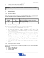
OPERATING INSTRUCTIONS
Getting Started
Charging the Battery
USB Memory Stick Preparation
Connecting the MMI to the Relay
Navigating Through the Menus
Monitoring Actual Data
Change or Viewing Settings
Change in MMI memory slots
Copy MMI memory slot to MMI memory slot
Upload relay settings to MMI memory slot
Download MMI memory slot to relay
Upload relay settings to USB stick
Download USB memory stick to relay
Retrieve and Uploading Event Records
Trouble Shooting (Frequently Asked Questions)
11
11
11
11
11
12
12
12
12
12
13
13
13
13
13
13
6.
6.1
6.2
6.3
6.4
6.5
DIAGRAMS
Physical Layout of Complete Instrument
Layout of the MMI Front Panel
Block Diagram of Instrument
Menu Structure
Mechanical Drawing
16
16
17
18
19
20
7.
7.1
7.2
ACCESSORIES
NewElec Li-Ion battery charger
NewElec USB memory stick
21
21
21
KX-MMI-420-EP
Page 3 / 21
1. ABSTRACT
The KD-MMI-420-EP (KD-Relay Man Machine Interface 4x20 Character Display) is a
portable, rechargeable battery powered unit, designed to function together with the KD or KE
motor protection relays. It is advisable to read this manual in conjunction with KD and KE
user manual. The display unit (MMI) is intrinsic safe and explosion proof certified, suitable
for use in potential dangerous environments (for example: coal mines).
The purpose of this unit is to provide a front-end facility (man machine interface) between the
operator and the motor protection relay. It is capable to monitor and adjust the motor
protection relay data. The relay data consists of settings, faults, events and actual data.
Settings can be adjusted as a batch or individually. Communication between the motor
protection relay and the display unit (MMI) is galvanic isolated and achieved via an infrared
(IrDA) serial link.
KX-MMI-420-EP
Page 4 / 21
2.
SPECIFICATIONS
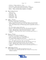
2.1
Electrical Requirements of MMI
•
•
•
•
•
2.2
The instrument is powered by a rechargeable Li-Ion battery pack
Operating time between charges – 10 hours
Battery charging time – 5 to 6 hours
Charger requirements:
◦ Input – 230Vac, 8 Watt.
◦ Output – 12Vdc, 500mA
Fuse – Slow blow 1 Ampere (5mm x 20mm).
Mechanical Properties of MMI
Physical dimensions – 325mm x 175mm x 135mm
Mass of unit – 1,85kg
Size of display on unit – 50mm x 20mm (character height - 5mm)
Display type – 4 lines by 20 characters liquid crystal display (LCD) with adjustable
back lighting.
• Size of characters in display window – 5mm
• Keyboard – diaphragm type (6 keys – up, down, left, right, enter and reset/menu)
• Indication lights – Light emitting diodes (6 LEDs - relay communication, in
service, trip, battery fault and charging)
•
•
•
•
2.3
Communication Link of MMI
• Infrared (IrDA)
• Communication speed – 19200 Baud (b/s)
• Maximum distance between units with no optical interference – Less then 1 meter.
2.4
Menu Structure with Unit Ranges of MMI
2.4.1 Main Menu (primary menu - 1st level)
• 1>Actual values
• 2>Relay settings
• 3>Faults
• 4>Events
• 5>MMI Settings
• 6>Relay Date Time (Real Time Clock)
• 7>Relay Info
2.4.2 Actual Values (2nd level)
• Load – Load current expressed in % (0 – 999%)
• TC level – Thermal capacity used expressed in % (0 – 100%)
• Vlev – Maximum Phase voltage (0 - 1200V), Vr – Red phase voltage (0 - 1200V)
• Vw – White phase voltage (0 – 1200V), Vb – Blue phase voltage (0 – 1200V)
• EL – Earth leakage (0 – 3000mA)
• Unbalance – Current unbalance (0 – 100%)
KX-MMI-420-EP
Page 5 / 21
•
•
•
•
•
Volt Sym – Voltage symmetry (0 – 50%)
Power Factor – Power factor expressed as a % (0 – 100%)
Iso. Lock – Isolation lockout expressed in k Ohm (0 – 200kOhm)
Relay 1 – Relay 1 operation status (energized / de-energized)
Relay 2 - Relay 2 operation status (energized / de-energized)
2.4.3 Relay Settings (2nd level)
• MMI Mem Slot
• Copy Slot → Slot
• DwnLd Slot → KX
• UpLoad KX → Slot
• DwnLd USB → KX
• UpLoad KX → USB
2.4.4 Faults – (2nd level)
Fault history retrieved from relay data base
• View [Nr] – Fault number x of 60 on display
• Status – Actual fault (caused by real current and voltage) or sim. fault caused
during simulation of current, voltage, power factor and earth leakage current)
• Type – Trip condition (Any one of the trip flags which is applicable at the time of
the trip)
• DT – Date and time stamp of fault record.
• Run hour – Motor running hours at the time of the trip expressed in hours.
• Current – Max current in % at the time the trip took place (0 – 999%).
• Voltage – Minimum phase voltage at the time of the trip (0 – 1200V)
• Contact R.T. - Contact release time or time to clear fault expressed in ms. (0 –
1000ms)
2.4.5 Events – (2nd level)
Event history retrieved from relay data base
• View [Nr] - Event number x of 2000 on display
• Status – Event type (alarm, trip or setting adjustment)
• DT – Date and time stamp of the event record.
• Alarm Flags – Alarm condition at the time of the recording of the event.
• Trip – Trip condition at the time of the event recording.
• Run hour – Motor running hours at the time of the recording of the event.
• Current – Maximum current at the time the event was recorded.
• Voltage – Minimum phase voltage at the time of the event recording.
• Contact R.T. - Contact release time or time to clear fault expressed in ms. (0 1000ms)
2.4.6 MMI Settings (2nd level)
System settings only for the MMI (not applicable for the relay)
• Auto scroll – Auto scroll the actual values after 5 minutes of no key activity
(Enabled / Disabled).
KX-MMI-420-EP
Page 6 / 21
• Back light auto on – Back light will be turned off after 5 minutes (Enabled /
Disabled).
• Contrast – Contrast adjustment of the LCD images (0 - 100%).
• Brightness – Brightness adjustment of the LCD back light (0 – 100%).
2.4.7 Relay Data Time - (2nd level)
• Date – Relay date adjustment of the real time clock of the relay.
• Time – Relay time adjustment of the real time clock of the relay.
2.4.8 Relay Info (2nd level)
Statistical and user data to manage the drive:
• Start-up counter – Increment every when the motor starts up (0 - 65535).
• Trip counter – Increment every time when a trip occurs (0 – 65535).
• Running hours – Increment every hour the of motor operation (0 – 65535).
• Drive description – Description of drive (20 characters).
• Drive file ID – Unique file name associated with the drive regarding event, fault
and setting files.
2.4.9 Settings (3rd level)
• TC Class Select – Thermal Curve Class (5 – 40sec)
• Maximum Load Set – Motor full load setting (10% - 100%)
• Voltage Select – Supply line voltage level (110V, 400V, 525V or 1050V)
• V Sym Trip Level – Voltage symmetry trip level (50% - 100%).
• Unbal Trip Level – Current unbalance trip level (0% - 50%)
• Unbal Trip Delay – Current unbalance trip delay (1 – 10 sec)
• U/C Trip Level – Undercurrent trip level (10 – 99%)
• U/C Restart Delay – Undercurrent restart delay (Manual, 10s, …, 1 h, 3h, 6h)
• U/C Trip Delay – Undercurrent trip delay (1 – 10 sec)
• EL Trip Level – Earth leakage trip level (0 – 3000 mA)
• EL Trip Delay – Earth leakage trip delay (100ms – 1sec, in steps of 50ms, IDT)
• EL Curve Select – Earth leakage curve select (Instantaneous Definite Time /
Inverse Definite Minimum Time)
• Starts per hour – Starts per hour allowed (0 – 30);
• U/C Startup Delay – Undercurrent start-up delay, pump priming time (0 – 200s)
• Power Fact Level – Power factor trip level setting (0 – 100%)
• TC Reset Level – Thermal capacity reset level (10 – 100%, default = 70%)
• Consec Start Lim – Consecutive starts limit (1 – 3)
• Run Stall T Level – Run-stall Trip Level (110% - 300%)
• Run Stall H Time – Run-stall hold off time (1 – 200s)
• U/C Trip – Undercurrent trip (Enable / Disable)
• Under Volt Trip (Enable / Disable)
• Over volt Trip (Enable / Disable)
• Volt Symt Trip – Voltage symmetry trip (Enable / Disable)
• Fail Safe – (Enable / Disable)
• Auto TC Reset – (Enable / Disable)
KX-MMI-420-EP
Page 7 / 21
•
•
•
•
•
•
•
•
•
•
•
•
•
•
•
•
•
•
•
•
•
•
•
•
•
•
•
•
•
•
•
•
•
•
•
•
•
•
•
•
•
•
•
•
Unbalance Trip – Current unbalance trip (Enable / Disable)
Phase Rot Trip – Voltage phase rotation trip (Enable / Disable)
Short Circ Trip – Short circuit Trip (Enable / Disable)
Single phase trip – (Enable / Disable)
Running Stall T – Run-stall trip (Enable / Disable)
Sel. U/C for Trip - Undercurrent / Power factor selected for trip (Enable / Disable)
Earth leakage Trip – Earth Leakage Trip (Enable / Disable)
Low Pass Filter – (Enable / Disable)
Iso. Lockout T – Isolation lockout trip (Enable / Disable)
Frequency Trip – Frequency monitoring (Enable / Disable)
Auto TC Reset Cal – (Enable / Disable)
Starts Per Hour – (Enable / Disable)
Volt Phase Rev – (Enable / Disable)
Vectorial Stall T – Vectorial stall trip (Enable / Disable)
Table 1 Mask 0&1 – 000:X, 001:X (X=0/1)
Table 1 Mask 2&3 – 010:X, 011:X (X=0/1)
Table 1 Mask 4&5 – 100:X, 101:X (X=0/1)
Table 1 Mask 6&7 – 110:X, 111:X (X=0/1)
Table 1 Input A – (Input pointer – see 2.4.10)
Table 1 Input B – (Input pointer – see 2.4.10)
Table 1 Input C – (Input pointer – see 2.4.10)
Table 2 Mask 0&1 – 000:X, 001:X (X=0/1)
Table 2 Mask 2&3 – 010:X, 011:X (X=0/1)
Table 2 Mask 4&5 – 100:X, 101:X (X=0/1)
Table 2 Mask 6&7 – 110:X, 111:X (X=0/1)
Table 2 Input A – (Input pointer – see 2.4.10)
Table 2 Input B – (Input pointer – see 2.4.10)
Table 2 Input C – (Input pointer – see 2.4.10)
Table 3 Mask 0&1 – 000:X, 001:X (X=0/1)
Table 3 Mask 2&3 – 010:X, 011:X (X=0/1)
Table 3 Mask 4&5 – 100:X, 101:X (X=0/1)
Table 3 Mask 6&7 – 110:X, 111:X (X=0/1)
Table 3 Input A – (Input pointer – see 2.4.10)
Table 3 Input B – (Input pointer – see 2.4.10)
Table 3 Input C – (Input pointer – see 2.4.10)
Timer A Time Out – (0 – 3000s)
Timer A Start In – (Input pointer – see 2.4.10)
Timer A Reset In – (Input pointer – see 2.4.10)
Timer B Time Out – (0 – 3000s)
Timer B Start In – (Input pointer – see 2.4.10)
Timer B Reset In – (Input pointer – see 2.4.10)
Start Motor – (hh:mm)
Stop Motor – (hh:mm)
Relay 2 Input Sig - (Input pointer – see 2.4.10)
KX-MMI-420-EP
Page 8 / 21
2.4.10 Input Pointers
It is signals that can be routed to the inputs of the logic functions, timers and relay 2.
Zero ('0')
One ('1')
InService
VoltPresentF
OverCrnt_af
ShortCirc_af
RunStall_af
I_Unbal_af
SinglePhase_af
EarthFault_af
EarthLeak_af
2.5
MinLoad_af
OverVolt_af
UnderVolt_af
VoltSym_af
HiFreq_af
LoFreq_af
IsoLockOut_af
OverCrnt_tf
ShortCirc_tf
RunStall_tf
I_Unbal_tf
SinglePhase_tf
EarthFault_tf
EarthLeak_tf
MinLoad_tf
OverVolt_tf
UnderVolt_tf
VoltSym_tf
HiFreq_tf
LoFreq_tf
IsoLockOut_tf
PhaseRot_tf
Environmental Rating
• Explosion proof certified
• Temperature range – 0°C to 60°C
• Humidity - < 85%
StartsPerHr_tf
Timer_A
! Timer_A
Timer_B
! Timer_B
RTClock
! RTClock
LogicFunc_1
! LogicFunc_1
LogicFunc_2
! LogicFunc_2
LogicFunc_3
! LogicFunc_3
Restart
FrozenContact
PLC_Inp0
PLC_Inp1
Tcap> THold
KX-MMI-420-EP
Page 9 / 21
3.
DEFINITIONS AND TERMINOLOGY
EEPROM
Electrical Erasable Programmable Read Only Memory (non volatile)
Flash memory
Similar to EEPROM (only block write - non volatile)
Galvanic isolation It is the principle of isolating functional sections of electrical system so
that charge-carrying particles cannot move from one section to another,
i.e. there is no electrical current flowing directly from one section to the
next. Energy and/or information can still be exchanged between the
sections by other means, however, such as by capacitance, inductance,
electromagnetic waves, optical, acoustic, or mechanical means.
In service
When the current rise above 10% of full load current it is assumed that
the motor is running.
Intrinsic safe
It is a protection technique for safe operation of electronic equipment in
explosive atmospheres. The concept was developed for safe operation of
process control instrumentation in hazardous areas. The theory behind
intrinsic safety is to ensure that the available electrical and thermal
energy in the system is always low enough that ignition of the hazardous
atmosphere cannot occur.
IrDA
Infrared serial data transmission link.
LED
Light emitting diode (It is used as visual indicators)
MMI
Man machine interface – It is a tool to monitor actual values, fault and
event records. It is also used to adjust the relay settings. In retrospect, it
is a more robust alternative, although not as comprehensive, for a laptop
computer with relay front-end software.
Motor protection
relay
It is an intelligent (computerized) unit monitoring an electric motor's
current and voltage supply. In case of overloading, phase lost etc. the
power supply of the motor will be interrupted by the protection relay to
prevent damage to the motor.
Slot
Memory space allocated to keep settings data for relay configuring
purposes.
Thermal Capacity It is a value expressed as a percentage to indicate the thermal condition
used
of the motor. It is based on the size, construction material, winding
isolation and cooling properties of the motor. When thermal capacity
reaches a value of 100%, it indicates that the motor has risen to it's
maximum temperature and any further temperature rise will cause
damage to the motor.
USB
Universal Serial Bus
USB drive
USB interface module for only the USB memory stick.
KX-MMI-420-EP
Page 10 / 21
4.
FUNCTIONAL DESCRIPTION
The KD-MMI-420-EP is packaged in a plastic toolbox and consists of the following function
blocks:
• Rechargeable Li-Ion battery pack
• Micro-controller
• Keyboard
• Liquid crystal display unit (LCD)
• Infrared serial port (IrDA)
• USB drive
Rechargeable Li-Ion battery pack - It is the power source of the portable MMI display unit.
The battery has to be charged with a NewElec Li-Ion battery charger before the MMI display
unit could be used. Battery endurance and charging times are listed under specifications.
Micro-controller – It is the core of the system. It provides processing power and enables all
the peripherals to function together as a unit. The micro-controller has on board memory for
program code, settings and temporary data.
Keyboard - It consists of six keys. The operator uses it to select and adjust the data of the
motor protection relay. Four keys are used for scrolling up, down, left and right respectively.
The remaining two keys are used to select (enter) and reset (return to the menu) respectively.
Liquid Crystal Display unit - It is a four line by twenty character display with back lighting
and contrast control. The display is used to display actual values and settings.
Infrared serial port (IrDA) - It is the serial communication interface between the relay and
MMI. The intention of the IrDA interface is to provide galvanic isolation between the relay
and the MMI. This enable the operator to download and upload data safely with minimal risk
of an explosion in hazardous environments.
USB drive - It is an interfaces only to the USB memory stick which is used for mass data
storage. The memory stick is plug-able and formatted according to the FAT32 file system.
This feature allows data to be viewed and edited in the office on a PC or Laptop equipped
with a USB port.
KX-MMI-420-EP
Page 11 / 21
5.
OPERATING INSTRUCTIONS
∆ Warning ! – Use only NewElec explosion proof certified devices to ensure
safe and reliable operation.
5.1
Getting Started
5.1.1 Charging the Battery
Before any operation could be performed ensure that the battery pack is properly charged.
Use the Li-Ion battery charger to charge the battery pack. The following conditions can be
indicated during the charge cycle by the battery fault and charging LEDs :
Battery Fault LED Charging LED
Flashing
Off
Off
On / Flashing
Off
Off
Condition Description
Battery is overheated, no charging is performed.
Battery is busy charging.
Battery fully charge. (5 to 6 hours).
5.1.2 USB Memory Stick Preparation
Important notes regarding USB memory stick preparation for data exchange:
• Use only explosion proof certified NewElec memory sticks.
• The memory stick needs to be formatted according to the FAT32 system 512MB
cache. Formatting is done on the USB port of the PC or the Laptop. Use Windows
Explorer to perform the task.
• Insert or remove the memory stick only when the MMI is powered down. Removal of
the memory stick while the MMI is busy may result in data corruption. A green flashing LED next to the USB connector of the MMI indicates read and write activity.
• Always ensure that the file names are not longer then eight characters for example
12345678.set
• The MMI has limited file functionality. The amount of file names is limited to 65535
names. No provision is made for renaming or deleting a file.
• Fault (filename.flt) and event (filename.evt) files can be viewed with MS Excel® or
any other equivalent software.
• Settings (filename.set) files can be viewed with the front-end software of the KD or
KE relay.
5.1.3 Connecting the MMI to the Relay
There are three connection points were the KD-Relay or KE-Relay can connect with the KDMMI-420-EP.
• KD-I2C-FLED IrDA panel.
• KD-RDU-420 IrDA panel.
• KD-IrDA module.
KX-MMI-420-EP
Page 12 / 21
The communication distance between the IrDA devices must be less then 1 meter. When
communication is established, the relay communication LED on the MMI will be solid on.
The in service LED indicates the motor's running status and the trip LED indicates the motor's
fault status. The motor will be switched off in the event of a trip condition.
5.2
Navigating Through The Menus
Navigating though the menus is done by using the direction buttons, enter key and reset key:
• UP button - It will scroll up in a menu or when in edit mode increment the parameter
value at the position of the cursor.
• DOWN button – It will scroll down in a menu or when in edit mode decrement a
parameter value at the position of the cursor.
• LEFT button - It will allow in edit mode to go left when editing a parameter value.
• RIGHT button – It will allow in edit mode to go right when editing a parameter value.
• ENTER button - It will allow going into a sub menu or confirm a change that was
done to a parameter value while in edit mode.
• RESET/MENU button - It will allow one level backwards in the menu structure or
reset the value that was changed while in edit mode.
5.3
Monitoring Actual Data
When auto scrolling is enabled the MMI Settings menu the display will automatically return
after five minutes of no keyboard interaction to the Actual menu.
5.4
Change or Viewing Settings
All features below can be found under the settings menu of the MMI. Range checking of
settings is done during editing.
5.4.1 Change in MMI memory slots
After selecting 'MMI memory', the MMI will prompt the operator to select a memory slot (1
to 4). After the selection has been made, the MMI will display all the settings of the selected
memory slot. When finding the setting to be altered, the enter-key has to be pressed in order
to alter the setting. A flashing cursor indicates that the setting is ready to be altered. The
enter-key must be pressed to confirm the change, while the reset key will restore the previous
value.
5.4.2 Copy MMI memory slot to MMI memory slot
MMI memory slot 5 is by default the memory slot where the relay settings will be uploaded to
when the MMI connects with the relay. When selecting copying memory slot the MMI will
prompt the operator to select from which memory slot (1 to 5) the data must be copied from.
After the operator selects a memory slot, the MMI will then prompt the operator to select a
destination memory slot (1 to 4). After selecting a memory slot the MMI will prompt the
operator for confirmation to overwrite destination memory slot.
KX-MMI-420-EP
Page 13 / 21
5.4.3 Upload relay settings to MMI memory slot
When the operator selects to upload relay settings the MMI will prompt the operator to select
the destination memory slot (1 to 4). The MMI will then prompt the operator to confirm the
the overwriting of the designated memory slot. The MMI will then proceed to upload the
relay settings.
5.4.4 Download MMI memory slot to relay
When the operator selects to download MMI setting to the relay. The MMI will prompt the
operator to select the memory slot (1 to 4) to be downloaded. The MMI will then prompt the
operator to confirm the the overwriting of the settings in the relay. The MMI will then proceed with download of the relay settings.
5.4.5 Upload relay settings to USB stick
When the operator selects to upload the relay settings to the USB memory stick, the MMI will
start uploading the relay settings to the MMI (memory slot 5). The MMI will then after-wards
download the relay settings to the USB memory stick. The unique relay ID or serial number
will be used as the file name what ever is available. The file extension will be 'filename.set'.
5.4.6 Download USB memory stick to relay
When the operator selects to download the relay settings from the USB memory stick, the
MMI will display a list of files that are available on the USB memory stick. After the
operator selected a file the MMI will ensure that the file is valid. The MMI will prompt the
operator to confirm the overwriting of the settings of the relay. The MMI will the proceed
with downloading of the relay settings.
5.5
Retrieve and Uploading Event / Fault Records
To retrieve event records the operator has to go to events menu. When arriving at the events
menu the operator has to select the amount of events required [10 – 2000]. When the enter
key is pressed the MMI will begin to upload events to MMI memory. After events are
uploaded an attempt will be made by the MMI to download the events data to the USB
memory stick.
Fault records are retrieved and uploaded in a similar way except for the fact that all the faults
[60] will be retrieved and uploaded on request.
The unique relay ID or serial number will be used as the file name what ever is available. The
file extension will be 'filename.flt' for faults and 'filename.evt' for events.
5.6
Trouble Shooting (Frequently Asked Questions)
Why does the KD-MMI-420-EP get stuck on the welcome screen ?
• It could be that the USB drive is not functioning properly.
KX-MMI-420-EP
Page 14 / 21
Why does the “COMMS” Green LED not come on ?
• Make sure the green light is on at both IrDA boxes.
• Make sure that there is a clear path between the IrDA devices.
• Make sure that the distance is shorter than a meter.
Why does the KD-MMI-420-EP struggle to read the files ?
• Make sure the file name being read is not longer than 8 characters.
• Make sure that the USB memory stick is formatted with the FAT32 format 512MB
cache.
• Cycle the KD-MMI-420-EP power and try again.
• Make sure that the green LED is on next to the USB memory stick.
• If still failing it could mean that the USB stick is not working properly.
Can faults / events be downloaded from KD-MMI-420-EP to the USB memory stick
without being connected to the relay ?
• Only when faults or events have been successfully uploaded from relay to the KDMMI-420-EP. If so, follow the next four steps.
• Break the connection between the Relay and the KD-MMI-420-EP.
• Go into events / faults again.
• Say yes to load the last events / faults loaded from a relay.
• The writing procedure will start again and the file will be saved to the last FILED
ID loaded from a relay.
Can the data be saved under a custom user file name (different file name) ?
• Due to limited memory space in the micro-controller, a fully functional DOS could
not be implemented to give the facility to delete, rename and create files.
• Future devices might have these features.
Why does KD_MMI-420-EP not seeing all the files ?
• The KD-MMI-420-EP is limited in the amount of files it can see on the USB drive.
It is due to code memory limitation.
• Only a total of 65535 files can be viewed.
• Feature devices will be looked at, to overcome this limitation.
Why is the screen not reading clearly ?
• Adjust the brightness in the MMI SETTINGS menu.
Why is the PC not detecting or reading any files on the USB memory stick ?
• The USB stick could have got corrupted when removing the USB stick while the
KD-MMI-420-EP was still busy with the drive.
• Format the USB memory stick according to the FAT32 file system 512 MB cache.
Always insert or remove USB memory stick when KD-MMI-420-EP is powered
down.
Why does it take a such long time to upload the events ?
• Due to the amount of events and the board rate of 19200 bits per second.
KX-MMI-420-EP
Page 15 / 21
• Future devices will be looked at to improve the rate of data exchange.
What steps have to be taken to open the event or fault file in a spreadsheet or wordprocessing application ?
• Find the file ID or serial number you are looking for on the USB memory stick.
• Right click on the file
• Go down to “Open With”.
• Select “Choose Program”
• Select your favorite spreadsheet or word-processing application.
• Click “OK”.
• Windows will remember the last application that you used to open the file.
• You can still open the file with a different application in the same way.
Can the file be viewed in a LINUX environment ?
• Yes, the file can be viewed in LINUX with a text editor or spreadsheet application.
Will a LINUX format works on the USB memory stick ?
• As long as the USB memory stick is formatted with a FAT32 file system, the KDMMI-420-EP USB driver will pick up the USB memory stick.
Can the USB memory stick be unplugged at any time ?
• No. Turn off the KD-MMI-420-EP before inserting or removing the USB memory
stick. This could lead to damage of the file system of the USB memory stick.
• If the USB memory stick becomes corrupted, it has to be again formatted (FAT32).
KX-MMI-420-EP
Page 16 / 21
6.
DIAGRAMS
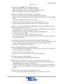
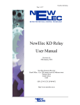
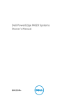
6.1
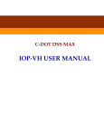
Physical Layout of the Complete Instrument
(Order number: FPR0220)
1
2
3
4
5
6
7
8
1 Liquid crystal display (4 x 20)
5
Fuse (Slow blow 1 Ampere)
2 Keyboard
6
Infrared interface unit (IrDA)
3 Indication lights (LED)
7
USB Memory stick
4 On / Off switch
8
Li-Ion battery charger
KX-MMI-420-EP
Page 17 / 21
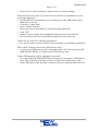
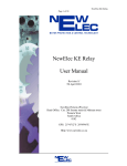
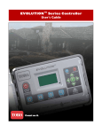
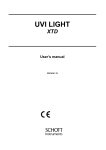
6.2
Layout of the MMI Front Panel.
1
2
3
4
5
6
7
8
9
10
11
12
1
Liquid display unit (4 x 20)
7
Left key
2
Up key
8
Communication indication
3
Enter key
9
In service (motor run) indication
4
Right key
10
Trip indication
5
Reset / Menu key
11
Faulty battery indication
6
Down key
12
Charge indication
KX-MMI-420-EP
Page 18 / 21
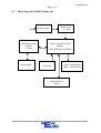
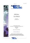
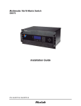
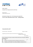
6.3
Block diagram of MMI display unit
Battery pack
(Li - Ion)
Battery charger
USB Memory Stick
Interface
(V Drive)
Memory stick
Micro-controller Unit with
Memory
(Flash, EEPROM and RAM)
Keyboard
Infrared Interface
(IrDA)
Liquid Crystal Display
(4lines x 20characters)
KX-MMI-420-EP
Page 19 / 21
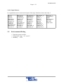
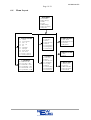
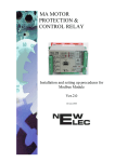
6.4
Menu Layout
MAIN MENU
1 Actual Values
2 Relay Settings
3 Faults
4 Events
5 MMI Settings
6 Relay Clock(RT C)
7 Relay Info
1. ACTUAL VALUES
1.1
1.2
1.3
1.4
1.5
1.6
1.7
1.8
1.9
1.10
1.11
I Load
T C level used
Vlev Vr
Vw Vb
EL
Unbalance
Volt Sym
P ower factor
Ioso Lock
Relay 1 (status)
Relay 2 (status)
2. SETTINGS
2.1
2.2
2.3
2.4
2.5
2.6
MMI Mem Slot
Copy Slot → Slot
DwnLd Slot → KX
UpLoad KX → Slot
DwnLd USB → KX
UpLoad KX → USB
3. FAULTS
3.1
3.2
3.3
3.4
3.5
3.6
3.7
View [Nr]
Status
Date & T ime
Run Hr
Current(Max)
Voltage(Min)
Contact R.T.
5. MMI SETTINGS
5.1 Auto Scroll
5.2 Backlight Auto On
5.3 Contrast
5.4 Brightness
6. RELAY CLOCK
4. EVENTS
4.1
4.2
4.3
4.4
4.5
4.6
4.7
4.8
4.9
View [Nr]
Status
Date & T ime
AlarmFlags
T rip Flag
Run Hr
Current(Max)
Voltage(Min)
Contact R.T.
6.1 Date
6.2 T ime
7. RELAY INFO
7.1
7.2
7.3
7.4
7.5
Start Up Cntr
T rip Cntr
Motor Run Hrs
Drv Description
Drv File ID
KX-MMI-420-EP
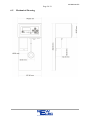
Page 20 / 21
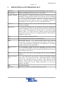
6.5
Mechanical Drawing
KX-MMI-420-EP
Page 21 / 21
7.
ACCESSORIES
All accessories are explosion proof certified and it is compulsory to be used for safety reasons
and reliable operation. All accessories are included when a new KD-MMI-420-EP is purchased. In case of lost or damage accessories can be reordered separately.
7.1
NewElec Li-Ion battery charger
Order information: NewElec Li-Ion battery charger (BAT0007)
7.2
NewElec USB memory stick
Order information: NewElec USB Memory Stick (CAB0028)
----ooOoo----