1
FCC User Information
WARNING: This equipment generates, uses and can radiate radio frequency
energy and if not installed and used in accordance with the instruction manual,
may cause interference to radio communications. It has been tested and found to
comply with the limits for a Class A computing device pursuant to Subpart B of
Part 15 of FCC Rules, which are designed to provide reasonable protection
against such interference when operated in a commercial environment. Operation
of this equipment in a residential area is likely to cause interference, in which
case the user at his own expense will be required to take whatever measures may
be required to correct the interference.
Limited Warranty
Communications Specialties, Inc. (CSI) warrants that for a period of three
years after purchase by Buyer, Beamer-V will be free from defects in material
and workmanship under normal use and service. A Return Material Authorization
(RMA) number must be obtained from CSI before any equipment is returned by
the Buyer. All material must be shipped to CSI, Hauppauge, New York, at the
expense and risk of the Buyer. Units returned to the Buyer will be shipped freight
collect.
CSI’s obligation under this warranty will be limited, at its option, to either
repair or replacement of defective units, including free materials and labor, at its
customer service facility in Hauppauge, New York. In no event shall CSI be
responsible for any incidental or consequential damages or loss of profits or
goodwill.
CSI shall not be obligated to replace or repair equipment damaged by fire,
war, acts of God or similar causes, or equipment that has been serviced, altered,
improperly installed or abused.
RMA numbers and repairs can be obtained from:
Communications Specialties Headquarters
Tel: (631) 273-0404
Fax: (631) 273-1638
Singapore Office
Tel: +65 6837 8790
Fax: +65 6333 0501
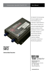
USER’S
MANUAL
Beamer-V
TM
Box Version
55 Cabot Court, Hauppauge, NY 11788
Tel: (631) 273-0404 Fax: (631) 273-1638
www.commspecial.com
Singapore Office
Tel: +65 6837 8790 Fax: +65 6333 0501
Introduction
Beamer-V is a high-quality, cost-effective fiber optic video transmission
system designed to transmit color and black and white signals over distances of
more than a mile. The system is easily installed and designed for long, troublefree operation in most indoor or outdoor-protected environments. Beamer-V is
compatible with all analog video standards, including NTSC, PAL and SECAM,
and will operate with all standard 62.5 micron fiber optic cables and industry
standard ST type connectors.
If you purchased part numbers 3100 or 3101, your product is supplied with:
1 Beamer-V Transmitter or Receiver unit
1 User's Manual
If you purchased part number 3105, your product is supplied with:
1 Beamer-V Transmitter unit
1 Beamer-V Receiver unit
1 User’s Manual
2 12 Vdc Power Supplies
Installation
See the diagram on the following page for assistance during installation.
Please note that Beamer-V Box units (transmitter P/N 3100 and receiver P/N
3101) may be used in conjunction with 2-channel card versions of Beamer-V
(transmitter P/N 3108A and receiver P/N 3109A). If you are connecting one or
more box units to a card unit, please refer to the manual that came with your
card unit for installation instructions regarding that portion of your system.
1.
Mount the Beamer-V transmitter at the camera or source of video to be
transmitted. Use the mounting tabs on the housing or the enclosed selfadhesive mounting pad.
Beamer-V is a trademarks of Communications Specialties, Inc.
P/N 102021 Rev D
CCTV Camera or
Other Video Source
exceed 250 ma. When power is applied, the red PWR indicator LED will
glow. Note that the (-) side of the power input is connected to the enclosure.
Video Monitor
or Other Receiver
6.
Connect the video monitor or other video receiving device to the BNC
connector on the Beamer-V’s receiver and the fiber optic cable plug to
the Beamer-V receiver’s optical connector.
7.
For a pleasing picture, slowly adjust the LEVEL control on the BeamerV’s receiver. If high accuracy is required, set this level to 1 volt pp with a
75 ohm load.
8.
Your Beamer-V video transmission system is now installed.
O O O O
Coaxial Cable
Coaxial
Cable
Beamer-V
Receiver
Beamer-V
Transmitter
ST type
Optical
ST type
Optical
Level
Adjust
62.5u Fiber Optic Cable
12 VDC
12 VDC
Power
Adapter
Power
Adapter
DC Common
+12VDC + 10%
Interface Troubleshooting
In rare instances, where the Beamer-V transmission system does not immediately
operate, the following “checklist” should be used:
1.
Is the correct operating power present and connected to the proper pins
on the power connector? If so, the red PWR LED should glow.
2.
If an external power source is being used, does it matter that the signal
and power ground are connected to the enclosure?
3.
Is a video signal present at the Beamer-V transmitter input?
4.
Is the proper 62.5 micron fiber optic cable being used?
5.
Is the length of fiber optic cable longer than 1.5 miles? If so, a weak,
snowy picture may result.
6.
Are the fiber optic connector ends free of any minute dust or dirt
particles? If there is any doubt, the use of a lint-free cloth moistened
with a drop of alcohol should be used to gently clean the optical surface.
Power Connector Details
Installation of Beamer-V Fiber Optic Transmission System
2.
Connect one of the plug-in power supplies to the input connector on the
Beamer-V transmitter. If an external power source is to be used, be
certain it provides regulated 12 volts CD+10%. Current from this source
will not exceed 250 ma. When power is applied, the red PWR indicator
LED will glow. Note that the (-) side of the power input is connected to
the enclosure.
3.
On the Beamer-V transmitter, connect the video signal to be transmitted
to the BNC connector and the ST fiber optic cable plug to the optical
connector.
If the above is correct and the system will still not operate properly, call our
customer service department for further assistance.
4.
Mount the Beamer-V receiver at the monitor or device where the video
will be received.
Standards to which conformity is declared:
5.
Connect the remaining plug-in power supply to the Beamer-V receiver’s
input connector. If an external power source is to be used, be certain it
provides regulated 12 volts DC +10%. Current from this source will not
CE Information
EMC
EN 55022: 1994, CISPR 22: 1993, Class B Limit
EN 50082-1: 1992
IEC 801-2: 1991; IEC 801-3: 1984: IEC 801-4: 1988
CCTV Camera or
Other Video Source
exceed 250 ma. When power is applied, the red PWR indicator LED will
glow. Note that the (-) side of the power input is connected to the enclosure.
Video Monitor
or Other Receiver
6.
Connect the video monitor or other video receiving device to the BNC
connector on the Beamer-V’s receiver and the fiber optic cable plug to
the Beamer-V receiver’s optical connector.
7.
For a pleasing picture, slowly adjust the LEVEL control on the BeamerV’s receiver. If high accuracy is required, set this level to 1 volt pp with a
75 ohm load.
8.
Your Beamer-V video transmission system is now installed.
O O O O
Coaxial Cable
Coaxial
Cable
Beamer-V
Receiver
Beamer-V
Transmitter
ST type
Optical
ST type
Optical
Level
Adjust
62.5u Fiber Optic Cable
12 VDC
12 VDC
Power
Adapter
Power
Adapter
DC Common
+12VDC + 10%
Interface Troubleshooting
In rare instances, where the Beamer-V transmission system does not immediately
operate, the following “checklist” should be used:
1.
Is the correct operating power present and connected to the proper pins
on the power connector? If so, the red PWR LED should glow.
2.
If an external power source is being used, does it matter that the signal
and power ground are connected to the enclosure?
3.
Is a video signal present at the Beamer-V transmitter input?
4.
Is the proper 62.5 micron fiber optic cable being used?
5.
Is the length of fiber optic cable longer than 1.5 miles? If so, a weak,
snowy picture may result.
6.
Are the fiber optic connector ends free of any minute dust or dirt
particles? If there is any doubt, the use of a lint-free cloth moistened
with a drop of alcohol should be used to gently clean the optical surface.
Power Connector Details
Installation of Beamer-V Fiber Optic Transmission System
2.
Connect one of the plug-in power supplies to the input connector on the
Beamer-V transmitter. If an external power source is to be used, be
certain it provides regulated 12 volts CD+10%. Current from this source
will not exceed 250 ma. When power is applied, the red PWR indicator
LED will glow. Note that the (-) side of the power input is connected to
the enclosure.
3.
On the Beamer-V transmitter, connect the video signal to be transmitted
to the BNC connector and the ST fiber optic cable plug to the optical
connector.
If the above is correct and the system will still not operate properly, call our
customer service department for further assistance.
4.
Mount the Beamer-V receiver at the monitor or device where the video
will be received.
Standards to which conformity is declared:
5.
Connect the remaining plug-in power supply to the Beamer-V receiver’s
input connector. If an external power source is to be used, be certain it
provides regulated 12 volts DC +10%. Current from this source will not
CE Information
EMC
EN 55022: 1994, CISPR 22: 1993, Class B Limit
EN 50082-1: 1992
IEC 801-2: 1991; IEC 801-3: 1984: IEC 801-4: 1988
FCC User Information
WARNING: This equipment generates, uses and can radiate radio frequency
energy and if not installed and used in accordance with the instruction manual,
may cause interference to radio communications. It has been tested and found to
comply with the limits for a Class A computing device pursuant to Subpart B of
Part 15 of FCC Rules, which are designed to provide reasonable protection
against such interference when operated in a commercial environment. Operation
of this equipment in a residential area is likely to cause interference, in which
case the user at his own expense will be required to take whatever measures may
be required to correct the interference.
Limited Warranty
Communications Specialties, Inc. (CSI) warrants that for a period of three
years after purchase by Buyer, Beamer-V will be free from defects in material
and workmanship under normal use and service. A Return Material Authorization
(RMA) number must be obtained from CSI before any equipment is returned by
the Buyer. All material must be shipped to CSI, Hauppauge, New York, at the
expense and risk of the Buyer. Units returned to the Buyer will be shipped freight
collect.
CSI’s obligation under this warranty will be limited, at its option, to either
repair or replacement of defective units, including free materials and labor, at its
customer service facility in Hauppauge, New York. In no event shall CSI be
responsible for any incidental or consequential damages or loss of profits or
goodwill.
CSI shall not be obligated to replace or repair equipment damaged by fire,
war, acts of God or similar causes, or equipment that has been serviced, altered,
improperly installed or abused.
RMA numbers and repairs can be obtained from:
Communications Specialties Headquarters
Tel: (631) 273-0404
Fax: (631) 273-1638
Singapore Office
Tel: +65 6837 8790
Fax: +65 6333 0501
USER’S
MANUAL
Beamer-V
TM
Box Version
55 Cabot Court, Hauppauge, NY 11788
Tel: (631) 273-0404 Fax: (631) 273-1638
www.commspecial.com
Singapore Office
Tel: +65 6837 8790 Fax: +65 6333 0501
Introduction
Beamer-V is a high-quality, cost-effective fiber optic video transmission
system designed to transmit color and black and white signals over distances of
more than a mile. The system is easily installed and designed for long, troublefree operation in most indoor or outdoor-protected environments. Beamer-V is
compatible with all analog video standards, including NTSC, PAL and SECAM,
and will operate with all standard 62.5 micron fiber optic cables and industry
standard ST type connectors.
If you purchased part numbers 3100 or 3101, your product is supplied with:
1 Beamer-V Transmitter or Receiver unit
1 User's Manual
If you purchased part number 3105, your product is supplied with:
1 Beamer-V Transmitter unit
1 Beamer-V Receiver unit
1 User’s Manual
2 12 Vdc Power Supplies
Installation
See the diagram on the following page for assistance during installation.
Please note that Beamer-V Box units (transmitter P/N 3100 and receiver P/N
3101) may be used in conjunction with 2-channel card versions of Beamer-V
(transmitter P/N 3108A and receiver P/N 3109A). If you are connecting one or
more box units to a card unit, please refer to the manual that came with your
card unit for installation instructions regarding that portion of your system.
1.
Mount the Beamer-V transmitter at the camera or source of video to be
transmitted. Use the mounting tabs on the housing or the enclosed selfadhesive mounting pad.
Beamer-V is a trademarks of Communications Specialties, Inc.
P/N 102021 Rev D