1
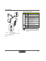
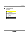
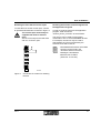
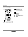
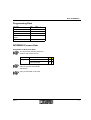
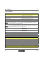
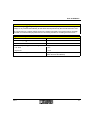
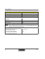
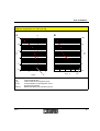
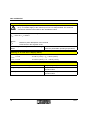
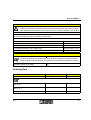
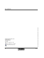
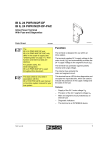
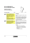
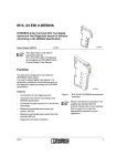
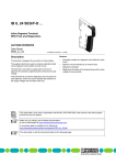
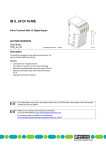
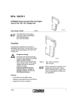
IB IL 24 SEG-ELF INTERBUS Inline Segment Terminal With Electronic Fuse Data Sheet 5657A 5 6 5 7 0 0 0 1 01/2000 This data sheet is intended to be used in conjunction with the INTERBUS Inline System Manual IB IL SYS PRO UM E. Function This terminal is a component of an INTERBUS Inline station. The segment terminal is used to create a partial circuit (segment circuit) within the main circuit. It is not used to supply power and has no elements for the protection against polarity reversal and surge voltage. This terminal has an LED for bus diagnostics and occupies two input data bits, which are used to indicate the status of the electronic fuse. 5 6 5 7 0 0 0 2 Figure 1 Features – Automatic creation of a segment circuit in the main circuit – Protection of the segment circuit using an electronic fuse with short circuit current limitation – Diagnostic indicators – Mapping the status of the electronic fuse in the INTERBUS input data – Resetting the fuse via INTERBUS or manually using an optional external button 5657A Terminal IB IL 24 SEG-ELF with connectors fitted Please note that the connector is not supplied with the terminal. Refer to the Ordering Data on page 13 to order the appropriate connector for your application. 1 IB IL 24 SEG-ELF Local Diagnostic Indicator E Des. Color Meaning D D S E G -E L F Green Bus diagnostics ON: INTERBUS is active Flashing: 0.5 Hz: Logic supply is present, INTERBUS not active 1 2 1 .1 1 1 2 .1 1 .2 2 2 2 .2 1 .3 3 3 2 .3 4 2 .4 1 .4 4 E 5 6 5 7 0 0 0 3 Figure 2 2 Hz: Communication power is present, I/O error 4 Hz: Logic supply present, local bus error OFF: Logic supply not present, INTERBUS not active Red Fuse in segment circuit (US) OFF: Fuse OK ON: Fuse has blown A blown fuse is indicated on both diagnostic indicators. The red LED E lights up and the green LED D flashes at 2 Hz. IB IL 24 SEG-ELF with the appropriate connector Function Identification Black 2 5657A IB IL 24 SEG-ELF Terminal Assignment The terminal points are only provided for measurement purposes and for connecting a manual reset button for the electronic fuse! Terminal Assignment Point 5657A 1.1 Connection of a manual reset button for the fuse (control input) 2.1 Connection of a manual reset button for the fuse (24 V) 1.2, 2.2 Measuring points for the main voltage UM 1.3, 2.3 Measuring points for GND of supply voltages 1.4, 2.4 Measuring points for the functional earth (FE) 3 IB IL 24 SEG-ELF Behavior of the Electronic Fuse Function of the Fuse Resetting the Fuse The fuse monitors the maximum nominal current in the segment circuit, which must not exceed 2.5 A. The terminal indicates the status of the fuse via LED E and via the two input data bits. There are three ways of resetting the fuse in an operational state: 1 Failure/deactivation and reactivation of the logic supply at the bus terminal module If the fuse blows, it remains in this state. The blown fuse is indicated by: 2 24 V pulse at the control input 3 Control signal from the application program via INTERBUS LED E ON LED D Flashing at 2 Hz (I/O error) Input bit IN0 = 0 and IN1 = 0 Error message Error messages to the higher-level control or computer system: Peripheral fault (PF) 4 5657A IB IL 24 SEG-ELF Resetting the Fuse Via the Control Input To reset the fuse via the control input, connect an optional external button as shown in Figure 3. The control input should only be supplied with 24 V to reset the fuse! Set the control input in the idle state with 0 V or leave it open. 1 Resetting the Fuse Via a Control Signal From the Application Program In order to reset the fuse from the application program, send the service "Control_Device_Function" of the firmware. This service can be used to send control commands to one or more INTERBUS devices. For example, the service may be used to acknowledge an I/O error triggered by the electronic fuse and to reset it. More detailed information on firmware services can be found in the "Firmware Services and Error Messages" User Manual IBS SYS FW G4 UM E (Order No. 27 45 18 5). 2 1 1 2 2 3 3 4 4 5 6 5 7 A 0 0 4 Figure 3 5657A Connection of a button for resetting the fuse 5 IB IL 24 SEG-ELF Internal Circuit Diagram Key: OPC IN T E R B U S O P C LED with details of the display designation "D" or "E" (see page 2) D U L INTERBUS protocol chip (bus logic including voltage conditioning) Optocoupler E L F E Electronic fuse Isolated area Other symbols are explained in the IB IL SYS PRO UM E User Manual. E L F + 2 4 V (U S ) + 2 4 V (U M ) 5 6 5 7 A 0 0 5 Figure 4 6 Internal wiring of the terminal points 5657A IB IL 24 SEG-ELF Programming Data ID code BEhex (190dec) Length code C2hex Input address area 2 bits Output address area 0 bits Parameter channel (PCP) 0 bits Register length (bus) 2 bits INTERBUS Process Data Assignment of IN Process Data The IN process data only maps the status of the electronic fuse. Bit view Bit 1 0 Assignment Fuse OK 1 1 Fuse has blown 0 0 The two bits can be at any position within a byte due to automatic addressing. OUT process data is not used. 5657A 7 IB IL 24 SEG-ELF Technical Data General Data Housing dimensions (width x height x depth) 12.2 mm x 120 mm x 71.5 mm (0.480 in. x 4.724 in. x 2.815 in.) Weight Approximately 44 g (without connector) Operating mode Process data operation with 2 bits Permissible temperature (operation) -25°C to +55°C (-13°F to 131°F) Permissible temperature (storage/transport) -25°C to +85°C (-13°F to 185°F) Permissible humidity (operation) 75% on average, 85% occasionally In the range from -25°C to +55°C (-13°F to +131°F) appropriate measures against increased humidity (> 85%) must be taken. Permissible humidity (storage/transport) 75% on average, 85% occasionally For a short period, slight condensation may appear on the housing if, for example, the terminal is brought into a closed room from a vehicle. Permissible air pressure (operation) 80 kPa to 106 kPa (up to 2000 m [6561.68 ft.] above sea level) Permissible air pressure (storage/transport) 70 kPa to 106 kPa (up to 3.000 m [9842.52 ft.] above sea level) Degree of protection IP 20 according to IEC 60529 Class of protection Class 3 according to VDE 0106, IEC 60536 Interface INTERBUS interface Through data routing Power Consumption Logic supply 7.5 V Current consumption from the local bus 30 mA, maximum Power consumption from the local bus 0.23 W, maximum Main voltage UM 24 V DC (nominal value) Nominal current consumption at UM 2.5 A (nominal value) Supply of the Module Electronics and I/O Through Bus Terminal/Power Terminal (UL, UM) Connection method 8 Through potential routing 5657A IB IL 24 SEG-ELF 24 V I/O Device Supply (UM, US) The main voltage UM is supplied by the bus terminal module or by a power terminal. The segment voltage US is provided automatically at this terminal and protected by the internal electronic fuse. No connections for a supply voltage exist on the segment terminal. The terminal points are only provided for measurement purposes and for connecting a button for resetting the blown fuse! Digital Control Input Number 1 Nominal voltage UIN 24 V DC Nominal current at UIN 5 mA Definition of operating points/switching thresholds Low level <5V High level > 15 V Permissible line length to the external button 5657A 30 m (98.43 ft.) (to ensure conformance with EMC directive 89/336/EEC) 9 IB IL 24 SEG-ELF Segment Circuit Protection Nominal voltage 24 V DC Permissible range 19.2 V DC to 30 V DC Nominal current 2.5 A Voltage drop at nominal current 0.5 V Short circuit current limiting Minimum 2.8 A Maximum 8A Behavior after error Latch function, i.e. remains switched off Closing resistor 60 mW Tripping time in the event of a short circuit 100 ms The fuse is tripped by a thermal overload protection. The tripping time depends on the ambient temperature and the level of the short circuit current. The data entered here applies for an ambient temperature of 25°C (77°F). The power supply unit must be able to provide a short circuit current of at least 8 A. Behavior when ground connection is interrupted 10 Leakage current when switched on (ON: logic supply present) 2 mA, maximum Output current when switched off (OFF: logic supply not present) 200 µA Output voltage when switched off 1V 5657A IB IL 24 SEG-ELF Time/Current Characteristic (A) and Time/Resistance Characteristic (B) on Ohmic Overload (Ambient Temperature TU = 25°C [77°F]) A B IG 1 0 0 0 1 0 0 1 0 0 1 0 1 0 1 1 t [s ] t [s ] 1 0 0 0 0 .1 0 .1 0 .0 1 5 6 7 IL [A ] Where t [s] IL [A] RL [W] IG Value K 5657A 8 K 0 .0 1 5 4 3 R 2 L [9 ] 1 0 K Typical tripping time Load current in the segment circuit Load resistance in the segment circuit Current limit (typical) Measured value on a hard short circuit 11 IB IL 24 SEG-ELF Power Dissipation To keep the power dissipation to a minimum, the control input must be in the idle state (0 V). A constant supply to the control input of 24 V is not permitted! This technical connection measure is the basis for the calculations below. Formula to calculate the power dissipation of the electronics PEL = 0.23 W + IL2 x 0.06 W Where Ptot IL Maximum power dissipation of the terminal Load current in the segment circuit Maximum power dissipation of the housing PHOU 0.6 W (within the permissible operating temperature) Derating on 30 V I/O Device Supply (UM/US) Maximum permissible load current in the segment circuit: ILmax = 2.5 A at -25°C (-13°F) TU +50°C (122°F) ILmax = 2.0 A at +50°C (122°F) < TU +55°C (131°F) Safety Devices Overload/short circuit in segment circuit Yes (see page 10) Surge voltage Components in the power terminal or the bus terminal module Polarity reversal Components in the power terminal or the bus terminal module 12 5657A IB IL 24 SEG-ELF Electrical Isolation To provide electrical isolation between the logic level and the I/O area, it is necessary to supply these areas from the bus terminal or from the bus terminal and a power terminal with separate power supplies. Interconnection of the 24 V power supplies is not allowed! Common potentials 24 V main power, 24 V segment voltage, and GND have the same potential. FE (functional earth ground) is a separate potential area. Separate system potentials consisting of bus terminal/power terminal and I/O terminal - Test distance - Test voltage 5 V supply incoming remote bus / 7.5 V supply (bus logic) 500 V AC, 50 Hz, 1 min. 5 V supply outgoing remote bus / 7.5 V supply (bus logic) 500 V AC, 50 Hz, 1 min. 7.5 V supply (bus logic) / 24 V supply (I/O) 500 V AC, 50 Hz, 1 min. 24 V supply (I/O) / functional earth ground 500 V AC, 50 Hz, 1 min. Error Messages to the Higher-Level Control or Computer System Overload/short circuit in segment circuit Yes If a short circuit occurs in the segment circuit, an error message is generated. LEDs D and E on the terminal also indicate the fault (see "Local Diagnostic Indicator" on page 2). Operating voltage out of range No Ordering Data Description Order Designation Order No. Segment terminal with electronic fuse IB IL 24 SEG-ELF 27 27 78 9 You need a connector for the terminal. Connector (black, w/o color print), pack of 10 IB IL SCN-PWR IN 27 27 46 2 Connector (black, with color print), pack of 10 IB IL SCN-PWR IN-CP 27 27 63 7 INTERBUS Inline System Manual IB IL SYS PRO UM E 27 43 04 8 5657A 13 © Phoenix Contact 01/2000 Subject to technical modification TNR 90 02 42 7 IB IL 24 SEG-ELF Phoenix Contact GmbH & Co Flachsmarktstr. 8 32825 Blomberg Germany + 49 - (0) 52 35 - 3-00 + 49 - (0) 52 35 - 3-4 12 00 www.phoenixcontact.com 14 5657A