1
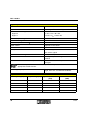
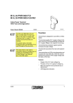
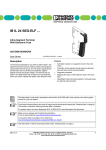
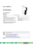
IB IL 120 DI 1 INTERBUS Inline Terminal With One Digital Input in the 120 V AC Voltage Area Data Sheet 5764B 5 7 6 4 1 0 0 1 09/2000 This data sheet is only valid in association with the INTERBUS Inline System Manual IB IL SYS PRO UM E. Function The terminal is designed for use within an INTERBUS Inline station. This terminal is used to detect digital input signals in the 120 V AC voltage area. Dangerous Voltage Connecting and disconnecting the terminal is only allowed if the power supply is disconnected. When working on the terminal and wiring, always switch off the supply voltage and ensure it cannot be switched on again. If these instructions are not followed, there is a danger of damage to health, or even of a life-threatening injury. 5 7 6 4 1 0 0 7 Figure 1 IB IL 120 DI 1 terminal with connector Please note that the connector is not supplied with the terminal. Please refer to Ordering Data on page 12 to order the appropriate connectors for your application. Features – Connections for one digital sensor – Maximum permissible load current 500 mA – Diagnostic and status indicators 5764B 1 IB IL 120 DI 1 Safety Instructions for Inline Terminals for Installation in Areas Outside the SELV (Low Voltage Area) Only qualified personnel may work on low voltage area Inline terminals. Qualified personnel are people who, because of their education, experience and instruction, and their knowledge of relevant standards, regulations, accident prevention and service conditions, have been authorized by those responsible for the safety of the plant to carry out any required operations, and who are able to recognize and avoid any possible dangers. (Definitions for skilled workers according to EN 50110-1:1996.) The instructions given in this data sheet must be followed during installation and startup. Technical modifications reserved. Correct Usage The terminal is only to be used within an Inline station as specified in this data sheet and the INTERBUS Inline System Manual. Phoenix Contact accepts no liability if the device is used for anything other than its designated use. This data sheet describes the module-specific features of the IB IL 120 DI 1 terminal. For general information on the INTERBUS Inline product family, please refer to the IB IL SYS PRO UM E INTERBUS Inline System Manual. 2 5764B IB IL 120 DI 1 General Description Local Diagnostic and Status Indicators D 1 1 2 0 D I1 Des. Color Meaning D Green Bus diagnostics 1 Yellow Input status indication Terminal Assignment Terminal Assignment Point 1 2 1 .1 1 1 2 .1 1 .2 2 2 2 .2 1 .3 3 3 2 .3 1 .4 4 4 1.1 Not used 1.2 Digital input 1.3 Connection of phase L 1.4 Neutral conductor connection (N) 2.1, 2.2, 2.3, 2.4 Not used 2 .4 5 7 6 4 1 0 0 2 Figure 2 IB IL 120 DI 1 with the appropriate connector Function Identification Cobalt blue with lightning bolt Housing/Connector Color Gray housing Gray connector, color-coded according to function 5764B 3 IB IL 120 DI 1 Internal Circuit Diagram Key: IN T E R B U S O P C OPC U L INTERBUS protocol chip (bus logic including voltage conditioning) LED Optocoupler Digital input Isolated area Terminal point, without metal contact Terminal point, without metal contact, with filler plugs L (1 2 0 V A C ) Other symbols are explained in the IB IL SYS PRO UM E User Manual. N 5 7 6 4 B 0 0 3 Figure 3 4 Internal wiring of the terminal points 5764B IB IL 120 DI 1 General Installation Instructions Installing the System Install the system according to the requirements of EN 50178. Starting Up an Inline Station An Inline station can only be started up if it has been properly installed. This means: – all terminals must be installed with their connectors – the station must be terminated with the end plate and the two end clamps Avoiding malfunctions The AC terminal must only be connected to the Inline station through an appropriate power terminal. The voltage should only be switched on when the AC area has been terminated with the end terminal and all the connectors are connected. The special features of the AC and SELV terminals and connectors are listed in the user manual and in the data sheets for the power terminals for AC areas. 5764B 5 IB IL 120 DI 1 Installation Instructions and Notes for an AC Area Dangerous Voltage Structure of an AC Area Please note that these are dangerous voltages when working on circuits that do not meet SELV requirements. An AC area must have an AC power terminal at one end and an AC end terminal at the other. Connecting and disconnecting terminals for the AC voltage area is only allowed if the power supply is disconnected. When working on terminals and wiring, always switch off the supply voltage and ensure it cannot be switched on again. I/O terminals that are suitable for this area can be used between these terminals. The number is limited by the system restrictions of the INTERBUS Inline station and the entire INTERBUS system (see IB IL SYS PRO UM E User Manual). 1 Please Use Grounded AC Networks B A R D R C L D 2 U L 3 4 U S U M B K -T Inline terminals for the AC voltage area should only be operated in grounded AC networks. 1 2 1 2 1 2 1 2 1 2 1 2 1 2 1 2 1 2 1 2 1 2 1 2 1 1 1 1 1 1 1 1 1 1 1 1 1 1 1 1 1 1 1 1 1 1 1 1 2 2 2 2 2 2 2 2 2 2 2 2 2 2 2 2 2 2 2 2 2 2 2 2 3 3 3 3 3 3 3 3 3 3 3 3 3 3 3 3 3 3 3 3 3 3 3 3 4 4 4 4 4 4 4 4 4 4 4 4 4 4 4 4 4 4 4 4 4 4 4 4 5 6 6 3 B 0 1 2 Figure 4 6 Example of an Inline AC area 1 Bus terminal 2 AC power terminal 3 Various AC input/output terminals 4 AC end terminal 5764B IB IL 120 DI 1 Fusing an AC Area Interrupting PE Jumpering in the AC Area Protect each AC area using an intrinsically safe fuse. The PE jumper begins at the power terminal of the AC area and, in a complete AC area, ends at the end terminal. Please note that the fuse required depends on the specific application. Connecting the Supply and the I/O in the AC Area Multiple supplies are not permitted If a terminal is removed from this area, the PE jumper is interrupted. As long as the installation instructions are followed, all subsequent terminals will be disconnected. The supply voltage must only be supplied to the power terminal for which it is meant. The connecting cables of all actuators and sensors should only be connected to the Inline AC terminals. The use of external bus bars for group voltages is not permitted. 5764B 7 IB IL 120 DI 1 Connection Example 1 D 1 2 0 D I1 1 2 1 1 2 2 3 3 4 4 Programming Data ID code BEhex (190dec) Length code C2hex Process data channel 2 bits Input address area 2 bits Output address area 0 bits Parameter channel (PCP) 0 bits Register length (bus) 2 bits Assignment of the Terminal Points for the IN Process Data Bit 1 0 Terminal Terminal point (signal) – 1.2 Terminal point (L) – 1.3 Terminal point (N) – 1.4 5 7 6 4 1 0 0 4 Typical sensor connections Observe the current carrying capacity The maximum total current flowing through the potential jumpers is 8 A. 8 Bit View N IN Figure 5 L (1 2 0 V ) INTERBUS Process Data Status indication LED 1 For the assignment of the bit view shown to your control or computer system, please refer to data sheet DB GB IBS SYS ADDRESS, Part No. 90 00 99 0. 5764B IB IL 120 DI 1 Technical Data General Data Housing dimensions (width x height x depth) 12.2 mm x 120 mm x 66.6 mm (0.480 in. x 4.724 in. x 2.622 in.) Weight 39 g (without connector) Operating mode Process data operation with 2 bits Sensor connection type 3-wire Permissible temperature (operation) -25°C to +55°C (-13°F to +131°F) Permissible temperature (storage/transport) -25°C to +85°C (-13°F to +185°F) Permissible humidity (operation) 75% on average, 85% occasionally In the range from -25°C to +55°C (-13°F to +131°F) appropriate measures against increased humidity (> 85%) must be taken. Permissible humidity (storage/transport) 75% on average, 85% occasionally For a short period, slight condensation may appear on the housing if, for example, the terminal is brought into a closed room from a vehicle. Permissible air pressure (operation) 80 kPa to 106 kPa (up to 2000 m [6562 ft.] above sea level) Permissible air pressure (storage/transport) 70 kPa to 106 kPa (up to 3000 m [9843 ft.] above sea level) Degree of protection IP 20 according to IEC 60529 Interface INTERBUS local bus Through data routing Power Consumption Communications power 7.5 V Current consumption from the local bus 30 mA, maximum Power consumption from the local bus 0.23 W, maximum I/O supply voltage 120 V AC (nominal value) Nominal current consumption on the I/O supply voltage Depends on the sensor Supply of the Module Electronics Through the Bus Terminal and of the I/O Through the Power Terminal Connection method 5764B Through potential routing 9 IB IL 120 DI 1 Digital Input Number 1 Input features According to EN 61131-2 Type 1 Definition of switching thresholds Signal 0 0 V AC UIN 40 V AC Signal 1 77 V AC UIN 135 V AC Nominal input voltage UIN 120 V AC Permissible range 108 V AC UIN 135 V AC Nominal input current for UIN 8.1 mA at 120 V AC, 60 Hz Total current Depends on the sensor Characteristic curve of the current Linear in the area 1 V < UIN < 135 V Delay time TON 40 ms, typical TOFF 10 ms, typical Permissible cable length to the sensor 30 m (98.425 ft.) Protection No integrated protection against short circuit and overload Behavior in the event of an error (short circuit) Protective element in the power terminal is damaged Short circuit protection can be achieved by means of a pre-connected fuse with an appropriate fusible element. Switching frequency Maximum network frequency, depending on bus length, data rate, and ambient conditions Input Characteristic Curve 10 Frequency (Hz) Input Voltage (V) Typical Input Current (mA) Active Power Loss (mW) 60 30 2.55 213 60 60 4.54 254 60 90 6.46 321 60 120 8.10 416 60 150 9.46 537 5764B IB IL 120 DI 1 Power Dissipation Formula to calculate the power dissipation of the electronics P E L = 0 .2 3 W Where PEL Z UIN + ( U Z IN )2 x 1 0 0 Ω+ U 2 IN 6 8 0 0 0 Ω Total power dissipation of the terminal Reactance (Z = 18813 W [60 Hz]) Input voltage of the input Power Dissipation of the Housing PHOU 0.7 W (within the permissible operating temperature) Concurrent Channel Derating None Safety Devices Overload/short circuit in phase L Using external fuse Surge voltage Protective circuits of the power terminal Electrical Isolation/Isolation of the Voltage Areas Common Isolated Groups Phase and neutral conductor have the same potential. PE is a separate potential area. Separate system potentials consisting of bus terminal/power terminal in the 24 V DC area and supply terminals/I/O terminals in the AC area - Test Distance - Test Voltage 5 V supply incoming remote bus/7.5 V supply (bus logic) 500 V AC, 50 Hz, 1 min 5 V supply outgoing remote bus/7.5 V supply (bus logic) 500 V AC, 50 Hz, 1 min 7.5 V supply (bus logic)/I/O area Routine test 2500 V AC, 50 Hz, 1 min 1200 V AC, 50 Hz, 1 min I/O area/PE 500 V AC, 50 Hz, 1 min Input/phase 500 V AC, 50 Hz, 1 min Error Messages to the Higher-Level Control or Computer System None 5764B 11 IB IL 120 DI 1 Ordering Data Description Order Designation Terminal with one digital input in the 120 V AC IB IL 120 DI 1 voltage area Order No. 28 36 70 6 I/O connector with 8 connections using the spring-clamp method (gray, with color print) pack of 10 IB IL SCN-8-AC-ICP 27 40 26 1 INTERBUS Inline System Manual IB IL SYS PRO UM E 27 43 04 8 © Phoenix Contact 09/2000 Subject to technical modification TNR 94 24 96 2 A connector is needed to complete the terminal. Phoenix Contact GmbH & Co Flachsmarktstr. 8 32825 Blomberg Germany + 49 - 52 35 - 30 0 + 49 - 52 35 - 34 12 00 www.phoenixcontact.com 12 5764B