1
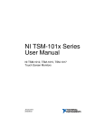
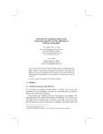
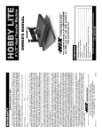
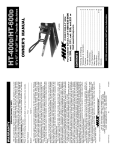
B-Bot
Biped Bot
User Guide
60073 V0113
Cautionary and Warning Statements
•
•
•
•
This kit is designed and intended for educational purposes only.
Use only under the direct supervision of an adult who has read and
understood the instructions provided in this user guide.
Read warnings on packaging and in manual carefully.
Always exercise caution when using sharp tools.
Principles at Work
Hydraulics
A hydraulic system is one that uses fluid as a force. The principle behind
a hydraulic system is simple: Force applied at one point is transmitted
to another point using a fluid.
Force
Force
Pushing on one end of a syringe filled with water (a hydraulic system)
creates an equal and opposite reaction on the other syringe. On the
B-Bot, a syringe is connected by a tube filled with water to a mechanical
part of the robot. Force is what causes the part to move.
Linear to Rotational Motion
The B-Bot is an example of reciprocal linear motion being converted
into rotary motion. The syringe being pulled back and forth – the
reciprocal linear motion – is converted into rotary motion – the gears
and hubs moving the legs – thanks to two one-way bearings and a
rack-and-pinion gear train.
One-Way Bearing
Operation
Engaged
Position
(axle turns
with gear)
Disengaged
Position (axle
does not turn
with gear)
Gear
Far side gear
Bearing roller
One-way bearing Far side bearing
Axle
Gear rack
Near side bearing
Near side gear
One-Way Bearing
Operation in B-Bot
Axle
rotates due
to rotation
of the far
side gear
Axle
rotates due
to rotation
of the near
side gear
The gear train features a top and bottom rack on the axle with the oneway bearings, so the linear motion moves the B-Bot forward no matter
which direction the syringe plunger goes.
2
B-Bot Biped Bot User Guide 60073 V0113
Materials Included
•
•
•
•
•
•
•
Bag of laser-cut parts
12 cc and 6 cc syringe
Tubing
Hub and bushing set
Axle
2 one-way bearings
4 spacers
•
•
•
•
•
•
•
4 – 1" screws
2 – 1/2" screws
7 – 3/8" screws
2 bushings
2 – #6 flanged spacers
4 – #2 flanged spacers
Piece of thread
Items Required (not included)
•
•
•
•
•
CA or white glue (such as HD Bond II)
Small Phillips screwdriver
File or emery sandpaper/cloth
Wire cutters
Small pliers (optional)
Building the B-Bot
1. Open the bag of laser-cut parts. Pop out any interior pieces that
need removed.
2. Lay Parts 1 and 2 flat with the number side facing up. Glue the Parts
3 into the center slots of 1 and 2 as shown.
3. Place a Part 4 on top of the 3s on each side. The “knob” should point
toward the man’s back. Let dry.
Steps 2-3
3
3
4
4
1
B-Bot Biped Bot User Guide 60073 V0113
2
3
4. Lay Parts 6 flat with the number side facing up. Glue a Part 5
lengthwise into each Part 6 in the two small slots.
5. Lay Parts 7 flat with the number side facing up. Glue the slotted end
of each Part 6 into a 7. Making sure these stay straight, let dry. These
are the legs.
Steps 4-5
6
5
7
6
5
7
6. Using wire cutters, trim off two edges of the Step 6
6 CC syringe plunger as shown.
7. Place the syringe plunger into the slots of
the Part 9 with the two circles on it (they
should face away from the plunger). Make
sure the trimmed edges of the plunger are
facing up and down, not side to side.
8. Place Part 10 over the plunger.
9. Place Part 8 on top so the two saw edges of Parts 8 and 9 face each
other. Insert two 3/8" screws from the side with the two circles. This
is the gear train assembly.
4
B-Bot Biped Bot User Guide 60073 V0113
Steps 7-9
Completed
assembly
9
10
8
3/8"
screws
10. Using a file or sandpaper, file off any rough edges on the ends of
the axle. Place a one-way bearing on the axle and notice how it will
spin in only one direction and that a tiny arrow on the side indicates
this. Remove the bearing.
11. Lay the two Part
Steps 10-13
12
11s on a flat surface
11
and center the
12
bearings inside
11
these so both
bearings will spin in
12
the same direction.
12. Place one Part 11
One-way
bearings
over a Part 12. Pick
this up and place
the other Part
Completed
11 on the other
assembly
side so Part 12 is
sandwiched between the other two pieces. Make sure to keep the bearings spinning in the same direction.
13. Insert an axle through the bearings and center it. Place a Part 12 on
both sides of the bearing assembly.
B-Bot Biped Bot User Guide 60073 V0113
5
14. Insert two bushings in the holes at the bottom of Parts 1 and 2.
Place the bearing assembly between Parts 1 and 2, inserting the
axle ends in the holes with the bushings.
15. Place two of the spacers between Parts 1 and 2 aligned with the
two holes in the torso. Insert 1" screws from the side of Part 2 to
secure. Tip: It may be easier to hold the spacers with the pliers to do
this.
Steps 14-16
Completed
assembly
1"
screw
Spacers
Bushing
Top
hole
Hub
1"
screw
Bearing
assembly
Bottom
hole
Bushing
Hub
16. Note that each hub has three holes. Place a hub on each side of the
axle so that one side has a hole at the top and the other has a hole
at the bottom (see photo above). If the hubs feel loose on the axle,
remove the hubs and insert a small piece of thread through the
center hole on the hub and reattach.
17. Insert the gear train assembly, gear rack first, down into the man’s
torso as shown. Make sure each gear rack engages one gear (Part
11). Make sure the syringe lips are inserted into the slots on Parts 1
and 2.
18. Place the other two spacers between the holes in the head and
secure them with the 1" screws as shown. Reach in and move the
gear train up and down – the hubs should spin forward.
6
B-Bot Biped Bot User Guide 60073 V0113
19. Through the
middle hole,
attach a leg to
each hubs with
3/8" screws so
that you are
screwing into the
top and bottom
holes pointed
out earlier.
After doing this,
make sure the
holes still point
in opposite
directions. If they
aren’t, use the
pliers to twist
them in place.
20. Place Parts 13
(the arms) under
the Parts 4 on
each side of the
torso. Using 1/2"
screws, secure
these through
the holes at the
top of the legs
(three parts will
be held together
on each side).
Be sure its snug
but the arms can
move.
21. With 3/8" screws,
fasten each Part
13 arm to the
hole on the Part
4 knobs.
Steps 17-21
Gear train
assembly
Spacers
1"
screws
3/8" screw &
#2 flanged
spacer
1/2" screw &
#6 flanged
spacer
13
13
3/8" screw &
#2 flanged
spacer
B-Bot Biped Bot User Guide 60073 V0113
Note: Screws and
spacers shown on
the left are repeated
on the right
7
Powering the B-Bot
1. Make sure the 6 cc syringe on the
Step 2
B-Bot is completely depressed.
2. With the 12 cc syringe depressed,
insert its tip into the cup of water
and pull back the plunger to fill the
syringe. Attach the tubing to the end
and depress the syringe to fill the
tubing with water.
3. Attach the other end of the tubing
to the syringe on the B-Bot. Remove
the 12 cc syringe and
refill it to the 10 cc mark.
Attach it again to the
tubing.
Completed
4. To operate the B-Bot, set
B-Bot
it on a flat surface such
as the floor, counter, or
tabletop. Depress the
12 cc syringe plunger
and then pull it back
out – continue to do this
to make the B-Bot move
forward.
P.O. Box 1708 • Pittsburg, KS 66762
shop.pitsco.com
Toll-Free Orders 800-835-0686
8
B-Bot Biped Bot User Guide 60073 V0113