1
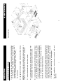
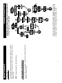
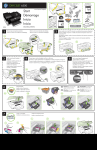
©2007 HIX Corp.
12
HT120205
Manufacturers of the Finest Quality Textile and Graphics Screen Printing and Heat Transfer Equipment
1201 E. 27th Terrace • Pittsburg, KS 66762 • U.S.A.
Web site: www.hixcorp.com • Phone: (800) 835-0606
E-Mail: [email protected] • Fax: (866) 561-0894
E-Mail: [email protected] • Fax: (866) 563-4600
This warranty applies to equipment manufactured by the HIX Corporation (HIX), Pittsburg,
Kansas, U.S.A. HIX warrants to the original purchaser, its Conveyor Dryers, Heat Transfer
Presses, Mug Presses, Mug Glazer, Retensionable Screen Frames, Textile Printers, Spot
Heaters, and Exposure Units against defects in workmanship and material, except for wear
and tear for a period of “One Year” from the date of purchase. HIX warrants its Accessories,
Reten Splines/Hardware/Tool Kit, and Shuttle for a period of 90 days from the date of purchase. DoughXpress and Thermatrol products are covered under separate warranty.
In the event of a defect, HIX, at its option, will repair, replace or substitute the defective item
at no cost during this period subject to the limitations of insurance and shipping costs stated
below.
In the case of heat transfer presses (except the Mug Press, Hobby Lite), HIX warrants the
heat casting for the “Life” of the machine for the original purchaser. If a part becomes obsolete
at the time for repair, and/or cannot be reasonably substituted for, HIX will credit, at half the
then current list price or last recorded price, only that part toward a new machine or any
product HIX offers. This credit offer shall be the sole responsibility of the HIX Corporation in the
event of an obsolete part.
This warranty does not cover belts, pads, mug wraps, mug press liners, canvas, rubber
blankets, bulbs, glass, PTFE or finish, rod ends, turn buckles on printers, or mug press or
damages due to accident, misuse/abuse, alterations or damage due to neglect, shipping or
lack of proper lubrication or maintenance. HIX shall not be responsible for repairs or alterations
made by any person without the prior written authorization by HIX. This warranty is the sole
and exclusive warranty of HIX and no person, agent, distributor, or dealer of HIX is authorized
to change, amend or modify the terms set forth herein, in whole or in part.
In the case of a problem with the equipment identified herein, HIX Corporation should be
contacted during regular business hours to discuss the problem and verify an existing warranty. HIX personnel will assist the customer to correct any problems which can be corrected
through operation or maintenance instructions, simple mechanical adjustments, or replacement of parts. In the event the problem cannot be corrected by phone, and upon the issuance
of a return authorization by HIX, the equipment shall be returned to HIX or an authorized
service representative. All insurance and shipment/freight costs are solely the responsibility
of the customer, and not that of HIX, and HIX shall not be responsible for improper handling or
damage in transit. HIX offers a reconditioning service and a core exchange/credit policy on
some models. HIX customer service personnel may be contacted for complete return authorization and reconditioning information.
This expressed warranty is given in lieu of any and all other warranties, whether expressed or implied, including but not limited to those of merchantability and fitness for a
particular purpose, and constitutes the only warranty made by HIX Corporation.
In no event shall HIX’s liability for breach of warranty extend beyond the obligation to repair
or replace the nonconforming goods. HIX shall not be liable for any other damages, either
incidental or consequential, or the action as brought in contract, negligence or otherwise.
This warranty gives you specific legal rights and you may also have other rights which
vary from state to state.
Model #: ____________________________ Serial #: ________________________________
Date Purchased: _____________________ From: _________________________________
HIX will automatically register the equipment on the date it was shipped to you or your
distributor. If the equipment was not purchased directly from HIX, but through a distributor
(either domestic or foreign), please keep a copy of their sales invoice showing the serial
number and date it was sold/shipped to you with this warranty. In this case, we will use the
distributor’s invoice date as the beginning warranty date. STAPLE A COPY OF YOUR RECEIPT TO THIS WARRANTY and keep in a safe place to provide verification of your warranty
should a problem occur. Thank you.
Please fill in the following information and attach a copy of your receipt for your records.
(Effective January 1, 2007)
WARRANTY
BEFORE warranty repair you MUST get Prior Authorization:
Receiving and Shipping ............................................................................ 2
Temperature & Instructions ....................................................................... 3
Pressure .................................................................................................... 3
Transfer Application ................................................................................... 4
Troubleshooting ........................................................................................ 5
Fuse Replacement .................................................................................... 6
Relay Bypass ............................................................................................. 7
Maintenance .............................................................................................. 8
Parts Identification ............................................................................... 9-10
Warranty ................................................................................................... 12
CONTENTS
For Customer Service, Call 1-800-835-0606
ext. 209, ext. 211, ext. 220, ext.221 or
Visit www.hixcorp.com
HT-600D
OWNER’S MANUAL
15”x15” / 16”x20” Heat Transfer Machines
HT-400D/HT-600D
2
1. Remove plywood shipping base.
CAUTION: Handle must be tied to base before moving or
shipping.
2. Plug the machine into the correct grounded electrical outlet.
The HT-600 requires a 20 amp receptacle.
WARNING: When using an extension cord, use 12 or 14
ga.-3 conductor. Maximum length, 25’ (7.62 m).
INSTALLATION
(Additional bottom boards, box and liners may be obtained
from your supplier for a nominal cost.)
1. Fasten machine to plywood shipping base with bolts provided.
2. Tie or tape handle securely to base.
3. Place in original box, and put side liner and top liner in place.
Fold in flaps and seal the box.
NOTE: Save all of your shipping/packing materials.
DO NOT RISK COSTLY SHIPPING DAMAGE!
SHIP ONLY IN ORIGINAL BOX.
SHIPPING OR RETURNS
Inspect your machine for hidden shipping damage. Contact
the delivery company immediately, should you find damage.
INSPECTION
Remember to save all packing materials - including box,
liner and board. You may need these for shipping your
machine or if a repair is necessary in the future.
UNPACKING
RECEIVING AND INSTALLATION
11
WARNING: For continued protection against risk of fire, replace with the following
fuses only: 120 Volt Units - Buss MDA-15; 220 Volt Units - Buss MDA-10.
# DESCRIPTION
Part # Qty.
31. Assembly Doghouse ............................................................ 1
30. Cordset ............................................................................... 1
29. Cord Grip ...............................................................13250
1
28. Fuse Holder ........................................................... 57118
1
27. Fuse ...................................................................................
26. Timer .................................................................................. 1
25. Dohouse Back ..................................................................... 1
24. EMI Filter ............................................................................ 1
46. Pin Handle Link ......................................................42129
1
47. Screw #14x1-1/4 Tap PHPH .................................... 59816
2
48. Assembly Handle Grip & Dowel ............................... 26856
1
PARTS IDENTIFICATION
#
1.
2.
3.
4.
5.
6.
7.
8.
9.
10.
11.
12.
23.
22.
21.
20.
19.
18.
17.
16.
15.
14.
13.
35.
36.
37.
38.
39.
40.
41.
42.
43.
44.
45.
34.
33.
32.
10
DESCRIPTION
Part # Qty.
Assembly HT400/600 Handle .................................. 10499
1
Assembly Link/Pin Main Arm .................................. 42110
1
Assembly Main Arm ............................................... 42404
1
Link Rocker ........................................................... 10502
2
Pin Rocker Link ..................................................... 42137
1
Nut 1/2" Push ........................................................ 20214 12
Knob Plastic .......................................................... 25143
1
Nut Jam 1/2-20 ...................................................... 25151
3
Block 2-1/2" Adj. Threaded ...................................... 25526
1
Pin Rocker Link Pivot ............................................. 41384
1
Assembly Top Adusting Rod ................................... 25208
1
Relay .................................................................................. 1
Terminal Board ....................................................... 72231
1
Screw #8x1/2 Tap-B PHPH ...................................... 21482 8
Bolt Lower Platen ................................................................. 2
Washer Spring ....................................................... 12378 12
Pin Main Arm Link .................................................. 41384
1
Spring #105 ........................................................... 49122
2
Nut 1/4-20 Hex .......................................................14548
4
Bolt 1/4-20x1-3/4 ....................................................10710
2
Switch ................................................................................ 1
Nut 1/2-20 Nyloc .................................................... 89078
1
Assembly Frame ....................................................41384
1
Washer 3/8" Hard ...................................................86504
4
Spacer Heatshield .................................................. 41384
4
Casting 1620 Lower ................................................ 82768
1
Pad 1/2" 1620 ........................................................ 50542
1
Casting Upper Heated .......................................................... 1
Heatshield ............................................................. 41384
1
Thermostat .......................................................................... 1
Thermometer ......................................................... 40345
1
Assembly Thermostat Cover .................................... 22640 1
Thermostat Knob ....................................................14217
1
Spacer Haysite ...................................................... 41384
2
Switch Rocker ..................................................................... 1
Lamp Red ........................................................................... 1
Decal Overlay ........................................................ 09970
1
PARTS IDENTIFICATION
3
1. The pressure control knob, located on the top of the machine,
should be set so that the heat head will lock down firmly.
2. Pressure is reduced by turning knob (with machine open)
counter-clockwise and increased by turning it clockwise.
NOTE: Adjustments may be required from one garment to
another and will vary to achieve the desired result.
CAUTION: Excessive pressure can cause structural
damage, voiding the machine warranty!
PRESSURE
5. Wait for the machine to reach your preset temperature by monitoring
the display temperature until it matches the set temperature.
4. When you have your desired settings press the menu button
a third time to lock in your settings otherwise the previous
settings will still be used.
3. To change or set the time, press the menu button on the digital
control. The light next to “TIME” will light. Press the up ▲, or
down ▼, button to your desired setting.
1. Turn on the machine by pushing the on/off switch.
2. To change or set the temperature, press the menu button on
the digital control. The light next to “TEMP” will light. Press the
up ▲, or down ▼, button to your desired setting.
TEMPERATURE & TIME INSTRUCTIONS
OPERATION
4
Specific application instructions are enclosed with each
transfer.
If a hot peel/split transfer is being applied, immediately peel
the paper after the machine has opened. DO NOT allow
the transfer to cool. If a cold peel transfer is being applied,
rub the transfer with an eraser or cloth and allow to cool for
5-10 seconds before removing the release paper.
5. Continuously peel the paper off the transfer (away from your
garment). NOTE: Do not fold the transfer back on itself.
Successful transfer work depends on the correct balance
of time, temperature and pressure. The type and thickness
of the material and the kind of transfer being used will
determine what settings are necessary.
4. Pull operating handle down locking the machine closed. After
the designated time has elapsed, open the machine.
3. Position the transfer and close the machine.
NOTE: Wrinkles may be removed by bringing heated platen in
contact with the garment before the transfer is positioned.
2. Align garment on the lower platen and smooth out the wrinkles.
1. Set the temperature, time, and pressure to the desired settings
as instructed on page 3. Always consult your specfic transfer
recommendations. Typical settings are: Cold Peel - 350°F
(177°C), 15 seconds and Hot Split - 375°F (190°C),
10-12 seconds.
TRANSFER APPLICATION
OPERATION
Exploded View
9
MAINTENANCE
8
You may clean the heat platen with steel wool, scrubbing aluminum
sponge, or fine wire brush.
Cleaning The Heat Platen
NOTE: Unplug the machine before lubricating.
Your press requires lubrication every 6 months. Using 3-in-1 oil (available from your hardware store), add one to two drops of oil at all
moving parts.
Lubrication
MAINTENANCE
5
*Customer Service Tech Sheets are available for this step.
Visit www.hixcorp.com to print or call 620-231-8568 and we
will send you one. Parts ordering is available on-line.
WARNING: Before making repairs, be sure on/off switch
is off and machine is unplugged!
TROUBLESHOOTING
6
3. Replace back cover of machine.
2. Remove blown fuse. Replace with the proper fuse.
HT-400: 120V=MDA-15; 220V=MDA-8
HT-600: 120V=MDA-15; 220V=MDA-10
1. Remove back cover of the machine and locate internal fuse
holder on inside of the machine.
WARNING: Before making repairs, be sure on/off switch is
off and machine is unplugged!
FUSE REPLACEMENT
REPAIRS
7
NOTE: Replace the relay if the machine starts heating. This is a
test only. Do not operate machine with relay bypassed.
5. Plug machine in and turn the power switch on.
4. Tighten the connection.
3. Loosen terminal #1 on relay and replace wire #26 along with
wire #12 under terminal #1.
2. Remove wire #26 from terminal #2 on relay.
1. Remove the back cover of the machine.
WARNING: Before making repairs, be sure on/off switch is
off and machine is unplugged!
RELAY BYPASS
REPAIRS