1
PW
5M-7M-9M-11M
Instructions for installation and use
English
Ver. : 11/2011
SA
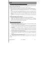
Summary Installation ...................................................................................... 2 1.1 General .............................................................................................................. 2 1.2 Operating conditions ......................................................................................... 3 1.3 Installation ......................................................................................................... 3 Operation ........................................................................................ 6 2.1 The Control Panel .............................................................................................. 6 2.2 Checks to be performed before operating the appliance ................................. 7 2.3 Starting the appliance ........................................................................................ 7 2.4 Checks to perform after operating the appliance ............................................. 7 2.5 Winterizing ........................................................................................................ 8 Maintenance ................................................................................... 8 3.1 Maintenance instructions .................................................................................. 8 3.2 Recycling the product ........................................................................................ 9 3.3 Additional recommendations ............................................................................ 9 Error codes .................................................................................... 10 FAQ................................................................................................ 11 Technical information .................................................................... 12 6.1 Technical specifications ................................................................................... 12 Warranties ..................................................................................... 12 Registration on line ........................................................................ 14 Conformity certificate .................................................................... 14 Available in the appendixes at the end of the manual: - electrical diagram - dimensions Please read this manual carefully before installing, maintaining or repairing this appliance! The symbol indicates important information that must be taken into account in order to avoid risk of personal injury and/or damage to the appliance. The symbol indicates useful information. As part of our continuous improvement policy our products may be subject to change without notice. H03579‐03.A1.SA Ver. 11/2011 1 Installation 1.1 General 1.1.1 Caution Exclusive use: heating swimming pool water (not be used for any other application), the product must be installed by a qualified technician according to the manufacturer’s instructions and in compliance with local regulations. The installer is responsible for the correct installation of the device and also for ensuring compliance with local regulations in this respect. The manufacturer will not be held responsible for any potential issues that may arise due to failure to comply with local regulations pertaining to installation, incorrect installation may cause serious damage and/or personal injuries (possibly death), that this device must be handled by competent and capable people (physically and mentally) who have received adequate instructions for use (by reading the user guide or as instructed by the installer). Persons who do not satisfy these requirements must not handle the appliance so as to avoid exposure to potentially dangerous parts. In the event of malfunction do not attempt to repair the appliance yourself: call your retailer, before working on the appliance, ensure that the power supply is disconnected and secured, Prior to any operation, check that: - The voltage on the identification plate of the appliance corresponds to the main voltage available on site, - the socket and the power supplied are adapted to the power requirements of the heat pump, and that they are grounded, - the electrical plug is adapted to the socket available. elimination or shunting of one of the safety leads automatically to the cancellation of the guarantee, as for the replacement of parts by non‐original parts, Keep the appliance out of the reach of children, Do not vent R410A into the atmosphere: R410A is a fluorinated greenhouse gas, covered by the Kyoto Protocol, with a Global Warming Potential (GWP) = 1975 ‐ (Directive of the EC 842/2006). 1.1.2 General terms of delivery, storage and transport Any equipment, including carriage and packing free, is shipped at the recipient’s risk. H03579‐03.A1.SA Ver. 11/2011 2 In the case of damage caused during shipping the recipient must mention any reservations in writing on the carrier's delivery note (confirmation to be sent to the carrier within 48 hours by registered mail and Acknowledgement of Receipt). If the appliance has been turned on its side, mention your reservations in writing to the carrier. 1.1.3 Contents X1 x2
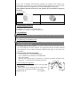
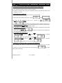
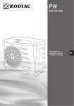
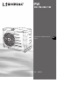
1.2 Operating conditions Operating range: between 7 °C and 32 °C of air temperature between 10 °C and 32 °C of water temperature 1.3 Installation Do not pick up the unit using the outer casing, use the base to lift and move the unit. 1.3.1 Selecting an installation site The appliance must be installed outdoors and there must be adequate open space surrounding it (see §1.3.3). the heat pump must be installed at a minimum distance from the end of the pool so as to avoid exposure to water splashes. The appropriate distance should be defined with reference to the national electrical standards that apply in the country of installation. The heat pump must not be installed: - near a heat source or near inflammable gas, - near a road with a risk of water and mud splashes, - facing strong wind, - with the vent facing toward a permanent or temporary obstacle (window, wall, hedge, etc…), it must be at least 3meters from such. Fixing holes 1.3.2 Installing the appliance place onto a stable, solid (concrete slab type) and level surface, protect from risks of flooding due to condensation produced by the appliance whilst it is operating. H03579‐03.A1.SA Ver. 11/2011 3 It is possible to fix the appliance to the ground using the holes in the base of the appliance or using fixing rails (not supplied). It is also possible to fix the appliance with brackets (not supplied). A drilling explanation diagram is available on the rear of the packaging box. 1.3.3 Hydraulic connections With by‐pass (recommended) Without by‐pass
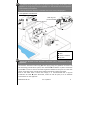
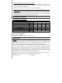
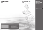
* Minimum distance filter water treatment by‐pass Respect the direction of the hydraulic connection (see § "Dimensions" in the appendix). Connections should be made using Ø50 PVC pipe, gluing the pipework connectors to the swimming pool filtration system, after the filter and before any water treatment system . In order to ensure the water tightness between these joints and the heat pump, wrap Teflon tape around the threading of the water intake and output. Even if the water flow is lower than 8m³/h, it is recommended that a by‐pass installation be used (valve VB closed, valves VE and VS open) so as to facilitate interventions on the appliance. H03579‐03.A1.SA Ver. 11/2011 4 Installing a by‐pass is mandatory if the water flow is higher than 8m³/h, use valve VB to adjust the water flow and leave valves VE and VS open. PW Test pressure bar
Operating pressure bar
Head Loss mCE
Minimum water flow‐rate m³/h
Average water flow‐rate m³/h
Maximum water flow‐rate* m³/h
* this flow‐rate must not be exceeded 5M
7M
9M
11M 4.95
5 5
5 6
1.5
2.3
2.45
2
3
4
8
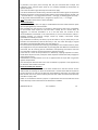
1.3.4 Electrical connections the unit is designed for connection to a general power supply with full earth and neutral or neutral earth systems, electrical protection: by circuit‐breaker (curve D) or fuse (Am), and with a 30 mA differential trip switch at the head of the supply line (circuit‐breaker or switch). Acceptable tolerance for tension variation: ‐10%, +7% (while operating) Risk of electrical shock inside the device. Only a fully qualified and approved technician should perform cabling connections inside the appliance. If the power cable is damaged it must be replaced by a qualified technician. PW 5M‐7M‐9M connect the power cord supplied with the appliance to a 16A socket complying with the standards and regulations in force in the country where it is installed, extension cords and adapters must not be used, If the power supply cable is not long enough, contact a qualified technician. PW 11 the electrical supply of the appliance must come from a protection and switching device (not supplied) complying with the standards and regulations in force in the country, the electrical supply cable must not be exposed to elements that are sharp, hot or represent a crush hazard, check that all cables are secure and all terminal connections are correct. Loose terminals may cause the supply terminal board to overheat, and will void the warranty. The appliance must be earthed. H03579‐03.A1.SA Ver. 11/2011 5 supply cable section: for cables of a maximum length of 20 metres (calculation base: 5A/mm²), must be checked and adapted depending on installation conditions PFP Voltage 11M 230V‐50Hz Maximum current consumption A 15.5
Cable section mm² 3 x 2.5 Electrical protection 3G2.5
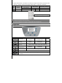
A 16 phase (L) + neutral (N) + Earth (PE) electrical conduits must be secured, use the stuffing box to bring the supply cable into the appliance. Operation 2.1 The Control Panel Symbol Designation water flow Heating external pump (option) ambient air temperature Default Not flashing Water flow is correct Flashing
Water flow to low or no water flow Off active Starting up inactive / Refer to the manual of the optional feature Sufficient insufficient / See §4 “on/off” button Button for displaying the temperature of the pool water or for setting parameters H03579‐03.A1.SA Ver. 11/2011 6 Symbol Designation
setting values buttons
Not flashing Flashing
Off 2.2 Checks to be performed before operating the appliance the hydraulic connections must be tight, the unit must be stable (as well as level and upright), the electrical supply cable must not be exposed to sharp or hot elements which could damage it or crush it. 2.3 Starting the appliance open the water supply and adjust the valves, if any (see §1.3.3), connect the heat pump to the power supply : to turn on the appliance: press for 2 seconds on then , : then by default the screen will display the requested temperature, to set the desired temperature ("requested temperature"): when the heat pump is operating, press on or to set the value. It’s possible to read the water temperature: when water is flowing through the heat pump, press on : fixed requested temperature, It’s possible to lock the keyboard: - lock the keyboard: press on flashes for 10 seconds then displays the and simultaneously for 3 seconds: will be displayed for 3 seconds then: , and simultaneously for 3 seconds: - unlock the keyboard: press on will flash for 4 seconds then: , 2.4 Checks to perform after operating the appliance After following the steps for running the heat pump, temporarily cut the water circulation to check that the heat pump stops operating: flow diode should flash. the water H03579‐03.A1.SA Ver. 11/2011 7 2.5 Winterizing Winterizing is essential due to the risk of the condenser freezing. This situation is not covered by the warranty.
switch off the heat pump by pressing the button for 2 seconds, then disconnect the power cable, ensure that no water is flowing through the heat pump, drain the water condenser (risk of freezing) by removing the two pool water inlet and outlet connections at the back of the heat pump, in the case of a full winterizing of the pool: connect the inlet and outlet connections "lightly" without tightening (one turn) in order to avoid foreign bodies entering into the condenser, in the case of winterizing the heat pump alone: do not reconnect the inlet and outlet connectors, instead place two stops (supplied) on the condenser water inlet and outlet. To avoid damaging the appliance with condensation, do not cover it with an air‐
tight cover.
Maintenance 3.1 Maintenance instructions A general servicing of the appliance is recommended both when winterizing and when restarting in order to ensure the proper operation of your heat pump, to preserve its performance and to prevent potential failures. Servicing costs will be borne by the user. Do not use a high‐pressure water hose. ensure that no foreign bodies obstruct the fan grid, clean the inside of the appliance, do not use solvent‐based cleaning products, clean the evaporator (for placing see§ “Dimensions” in appendix) with a soft brush and a fresh water hose (disconnect the power cable), do not twist or bend the metal blades, check the correct operation of the regulator, check that the condensation is drained properly whilst the appliance is operating. The following operations must be performed by a qualified technician: check the correct working condition of all safety components, check that all metal elements are earthed, check the tightening and connections of the electric cables and the cleanliness of the electrical equipment box, H03579‐03.A1.SA Ver. 11/2011 8 3.2 Recycling the product This symbol means that the equipment must not throw it into your household waste. It will be collected selectively so that it can be reused, recycled or recovered. Any substances it may contain which are potentially dangerous to the environment will be eliminated or neutralised. Enquire with your retailer for the conditions that apply to the recycling of your product. 3.3 Additional recommendations In relation with the Pressurised Equipment Directive (PED‐97/23/CE) 3.3.1 Installation and maintenance the unit may not be installed close to combustible materials, or the air duct inlet of an adjacent building. for certain appliances, it is essential to fit protection grids if the unit is installed in an area which is unprotected and easily accessible. during installation, repair and maintenance work, it is strictly prohibited to step on pipes and hoses as these could break and the escaping refrigerant could cause serious scalding. when servicing the appliance, the composition and state of heat carrying fluid must be checked, as well as the absence of any refrigerant. during the annual unit sealing test in accordance with valid legislation, the high and low pressure switches must be checked to ensure they are securely fastened to the refrigeration circuit and that they shut‐off the electrical circuit when tripped. during maintenance work, ensure there are no traces of corrosion or oil around refrigeration components. before beginning work on the refrigeration circuit, isolate the appliance and wait several minutes before removing the temperature or pressure sensors. Certain elements such as the compressor and associated piping may attain temperatures in excess of 100°C and high pressures with the consequent risk of severe scalding. 3.3.2 Repair all brazing work must be carried out by a qualified brazer/welder, replacement pipes must always be made of copper in compliance with standard NF EN 12735‐1. leak detection, pressure test: - never use oxygen or dry air, risk of fire or explosion, - use dry nitrogen or the mixture of nitrogen and refrigerant indicated on the name plate, - the test pressure for both the high and low pressure circuits must not exceed 42 bar. H03579‐03.A1.SA Ver. 11/2011 9 the high pressure circuit pipes are made of copper and have a diameter equal to or greater than 1’’5/8. A certificate as indicated in §2.1 in compliance with standard NF EN 10204 will be requested from the supplier and filed in the installation technical documentation. the technical data relative to the safety requirements of the various applicable directives must be indicated on the name plate. This data must be recorded in the unit installation instructions which are included in the installation technical file: model – code – serial number, maximum and minimum OT, OP, year of manufacture, EC label, manufacturer’s address, refrigerant and weight, electrical parameters, thermo‐dynamic and acoustic performance. Error codes Display Designation
Cause
Air Sensor faulty or temperature disconnected sensor fault Defrost sensor fault Sensor defective or disconnected Low pressure fault Gas leak on the refrigerating circuit Insufficient water flow or faulty flow sensor High pressure fault Other Solution Replace the sensor, contact your retailer or a qualified technician Replace the sensor, contact your retailer or a qualified technician Contact your retailer or a qualified technician Check the water flow or contact your retailer or a qualified technician Contact your retailer or a qualified technician Replace the sensor, contact your retailer or a qualified technician Wait until the air temperature reaches the operating temperature range Contact your retailer or a qualified technician Clean the evaporator (see §2.1) Water Sensor defective temperature sensor fault or disconnected Ambient air temperature too low The fan is not Defrost operational cycle fault The evaporator is (>20 minutes) clogged up Value for air Contact your retailer or a temperature or qualified technician defrost is incorrect H03579‐03.A1.SA Ver. 11/2011 10 FAQ Is it possible to improve the temperature performance? A heat pump is designed to extract heat from the surrounding air and transfer it to the pool water. The higher the air temperature, the more heat the heat pump will be able to transfer to the pool water. Setting the setpoint to maximum will not heat the water any faster. In order to improve the efficiency of your heat pump it is recommended that you: - protect the pool with a cover (floating cover, roller cover …), so as to avoid heat loss, - choose periods when the outside temperature is mild (> on average 10° C) in order to facilitate the temperature increase (this may take several days. The actual time will vary according to weather conditions and the power of the heat pump), - the higher the surrounding air temperature, the more efficient the heat pump will be. Check that the filtration time is sufficient: ‐ during the heating phase, water circulation must be continuous (24h/24), ‐ maintain the temperature throughout the season, allow for an "automatic" circulation of at least 12 hrs/day (the longer this time is, the more time the heat pump will have to function and to heat the water). Why is my heat pump not heating? Several reasons could explain this situation: 1. At start‐up the appliance remains on "pause" for 30 seconds before actually starting up: check that this time has passed, 2. once the pool has reached the required temperature, the heat pump switches off: check that the water temperature is lower than the requested temperature (see §2.4), 3. when there is no water flow or when it is insufficient, the heat pump will stop: check that water is flowing correctly through the heat pump, via an external circulation system, that the pipework connections are correct and check that the "water flow" diode is lit and not flashing, 4. when the outdoor air temperature drops below 7°C, the heat pump will stop: check the outdoor temperature as well as the "surrounding air temperature" indicator 5. The heat pump may have detected a malfunction: check to see if an error code is displayed on the screen, if so refer to §4. If the problem persists after you have checked all the above points, contact your retailer. H03579‐03.A1.SA Ver. 11/2011 11 The heat pump is giving off water: is this normal? Your appliance will give off water in the form of condensation. This water is the humidity contained in the air which condenses on contact with certain cold components inside the heat pump. Caution: your appliance can drain several litres of water per day. Where should my water treatment system be positioned with respect to the heating system? The water treatment system (chlorinator, salt chlorinator, etc…) must be installed preferably downstream from the heat pump (see installation §1.3.3), and must be compatible with the latter (check with the manufacturer). Technical information 6.1 Technical specifications PW 5M
7M
9M Single phase voltage
230V‐50Hz Power consumption* kW
0.98
1.56
2.06 Power restored* kW
4.65
6.52
8.6 Nominal current consumption*
A
4.45
7.09
9.36 COP* 4.7
4.2
4.2 Sound power dBA
65.4
66.7
69 Sound pressure at 10 meters
dBA
37.4
38.7
41 Protection calibre A
16
* with an ambient air of +15 °C and a pool water of 24 °C, humidity 70% unit protection class: IP 24 refrigerant gas: R410A refrigerant charge: see product information plate 11M 2.6 10.5 12.4 4.1 72 44 Warranties Principle Unless otherwise stipulated, we contractually guarantee the correct operation of our new Products. We guarantee that our Products conform to their technical specifications and that they are free of material and manufacturing default. The present warranty is limited, at our discretion, either to the repair or exchange for a new or repacked Product, or to the refund of any Products recognized as being defective by our services. Shipping expenses for the repaired or replaced Products delivered to the client will be borne by us. The guarantee excludes any labour costs, travel and/or accommodation expenses incurred as the result of repairs made outside of continental France and excludes any payment of damages. All Product returns must first be approved and determined by our services. Returns sent by the Client without our prior approval will not be accepted. H03579‐03.A1.SA Ver. 11/2011 12 In particular, the spare parts warranty will only be honoured after analysis and inspection of the returned spare parts by our company followed by the decision to replace said parts. In all cases the seller's legal warranty will continue to apply. In order to benefit from the warranty, the Client and the End User agree to respect the following parameters concerning the water balance of the swimming pool: pH: 6.8 < pH < 7.6; free chlorine: < 3,0 mg/L; total bromine: < 5.0 mg/L; stabilising agent (if used): < 75 mg/L; total dissolved metals (iron, manganese, copper, zinc…) : < 0.1 mg/L Note: using water drawn from a well is forbidden. General limitations The present warranty does not apply to visible defects that the Client failed to report upon accepting delivery of the Products. Also excluded from the warranty are: defects or deterioration due to the unsuitability of the Product with respect to the end User's needs, due to normal wear, to negligence, to incorrect installation or to a use that does not conform to the recommendations mentioned in the User Manual, to lack of maintenance and/or a handling accident, to incorrect storage, and/or by studies, instructions and/or specifications made by our Client. Any modifications made by the Client, by the End User or by any third party to our Products will automatically void the warranty in full. The same will apply if original parts were to be replaced with spare parts not sold by us. Our Client will be responsible for ensuring compatibility of our Products with any other pool equipment it may be installed with, by checking with the different manufacturers concerned, also for ensuring that all installation and operating instructions and rules are respected in order for the overall system to operate correctly. In the case of a return of the product to our workshop, shipping expenses to and fro, will be borne by the end user, except for those expenses mentioned under paragraph 2 of the present article. Immobilisation and deprivation of use of an appliance due to repair will not give the right to compensation. This warranty will become void in the case of a default in payment or late payment by our Client for the Product concerned. Period covered by the warranty The effective warranty start date is the date mentioned on the sales invoice for the new Product as issued by our Client to the End User. This document will be required as proof of purchase in order for the warranty to be effective. Failing this, our Client shall bear the full cost of any claims made by the end User under the contractual warranty and after its expiry date. Under no circumstances shall any repairs or replacements carried out under the terms of this warranty cause its duration to be extended or renewed. H03579‐03.A1.SA Ver. 11/2011 13 Particular dispositions for Products of Heating and Dehumidification range Unless otherwise specified, we guarantee the correct operation of our new products installed and put into service by a professional installer (excluding installation via "retrofit" kit") for a period of two years starting from the date mentioned on the invoice as issued by our Client to the end User. Users are also required to have an approved technician perform regular maintenance on our products, as detailed in the instructions in the product user guide. The warranty only covers defaults in materials and craftsmanship that have been acknowledged by our technical department/services. The present warranty does not apply to malfunctions and/or degradations due to external factors unrelated to us (poor power supply, adjustment of the bypass, incorrect air circulation, bad insulation of the premises, thermal bridges, incorrect winterization, etc.…). The heat exchanger of the heat pumps benefits from a 5‐year warranty against corrosion. For any warranty issues, please contact your local retailer.
We recommend that you keep your purchase invoice safe, if you require assistance for your product. Registration on line Register your product on our website: - you will be the first to be informed of new Zodiac products and special offers, - You can help us to constantly improve the quality of our products. Australia – New Zealand
South Africa
Europe and rest of the world
www.zodiac.com.au
www.zodiac.co.za
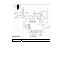
www.zodiac‐poolcare.com Conformity certificate Z.P.C.E. declares that the herewith products or ranges: Swimming pool Heat pumps: Zodiac Power 5M‐7M‐9M‐11M are in conformity with the provisions: of the ELECTROMAGNETIC COMPATIBILITY directive 89/336/EEC. of the LOW VOLTAGE directive 73/23/EEC. H03579‐03.A1.SA Ver. 11/2011 14 Electric diagram PW 5M‐7M‐9M English
P1
Power supply 230V‐1N‐50Hz
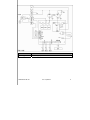
H03579‐03.A1.SA Ver. 11/2011 1 PW 11M
English
L‐N‐PE
Power supply 230V‐1N‐50Hz
H03579‐03.A1.SA Ver. 11/2011 2 AF C1 C2 C3 CD E1 E2 ED1 F1 KM1 KM2 KM3 KM4 M1 M2 M3 SD1 SD2 SD3 T1 Digital display Earth Compressor capacitor Fan capacitor Auxiliary pump capacitor
Flow rate controler High pressure switch Low pressure switch Auxiliary pump Fuse Compressor relay Fan relay Auxiliary pump relay Complementary relay Compressor Fan Auxiliary pump (150W‐200W maximum)
Water temperature sensor
Air temperature sensor
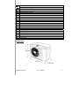
Defrost sensor Transformer Dimensions H03579‐03.A1.SA Ver. 11/2011 3 PW 5M 7M 9M 11M weight (Kg) 45 47 48
51
English pool water inlet
pool water outlet Evaporator H03579‐03.A1.SA Ver. 11/2011 4 Zodiac Innovative pool products and services
Votre revendeur / your retailer
Pour plus de renseignements, merci de contacter votre revendeur.
For further information, please contact your retailer.
Hinweise und Auskünfte erhalten, Sie bei ihrem Händler.
Voor nadere inlichtingen kunt u zich wenden tot uw zwembadbouwer.
Para cualquier información adicional, contactar con su detallista.
Per qualsiasi informazione supplementare, mettetev in contatto con il vostro rivenditore.
ZODIAC® is a registered trademark of Zodiac International, S.A.S.U., used under license.
ZODIAC POOL CARE EUROPE / BP 90023, 49180 St Barthélémy d’Anjou cedex-France / S.A.S.U AU CAPITAL DE 517 200 E / SIREN 395 068 679 / RCS PARIS / Pour Qui Pourquoi / H03579-03.A