1
Instructions for installation and use
English
More documents on:
www.zodiac-poolcare.com
H0470400.A - 2014/09
EN
•Read this manual carefully before installing, maintaining or repairing this appliance!
•The symbol
indicates important information that it is imperative to take into consideration in
order to avoid all risks of harm to persons or damage to the appliance.
•The symbol
indicates useful information.
Warnings
•As part of a continuous improvement process our products may be modified without prior notice.
•Exclusive use: salt water chlorination system for pools (must not be used for any other purpose).
•System designed to operate with water from the public mains supply. Use of well water or rain water is prohibited.
•The appliance must be installed by a qualified technician in compliance with the manufacturer’s
instructions and with applicable local standards. Under no circumstances can the manufacturer be
held liable in the event of failure to comply with applicable local standards. Under no circumstances
shall the manufacturer be held liable if current local installation regulations are not followed.
•It is important that this equipment is operated by competent and qualified (both physically and
mentally) people that have previously received the instructions for use (by reading this booklet).
Any person not meeting these criteria should not go near the equipment, to avoid the risk of being
exposed to dangerous components.
•If the equipment malfunctions: do not attempt to repair the equipment yourself – contact your
installer.
•Before working on the equipment, ensure that it and any other equipment connected to it are
disconnected from the electricity supply.
•Before all connections, make sure that the voltage indicated on the maker's plate of the appliance
corresponds to the mains voltage.
•Removing or bypassing one of the safety devices automatically voids the guarantee, as does fitting
replacement parts not manufactured by us.
•Incorrect installation can result in damaged equipment or serious physical injury (or even death).
•Keep the equipment out of the reach of children.
1
H0470400.A - EN - 2014-09
Contents
1. Information before installation............................................................................... 3
1.1 General delivery conditions................................................................................................................ 3
1.2 Contents............................................................................................................................................. 3
1.3 Technical specifications....................................................................................................................... 3
2. Installation.............................................................................................................. 3
2.1 Preparing the pool: water balance..................................................................................................... 3
2.2 Installing the control box.................................................................................................................... 4
2.3 Installing the cell................................................................................................................................. 4
2.4 Installing the flow controller (Ei² Expert only).................................................................................... 5
2.5 Electric connections............................................................................................................................ 5
3. Use......................................................................................................................... 6
3.1 Description of the Ei² user interface .................................................................................................. 6
3.2 Description of the Ei² Expert user interface........................................................................................ 7
EN
4. Maintenance........................................................................................................ 10
4.1 Washing the pool filter (backwash).................................................................................................. 10
4.2 Cleaning the electrode...................................................................................................................... 10
4.3 Wintering.......................................................................................................................................... 11
5. Troubleshooting.................................................................................................... 11
6. Registering the product......................................................................................... 12
7. Product conformity............................................................................................... 12
H0470400.A - EN - 2014-09
2
1. Information before installation
1.1 General delivery conditions
All equipment, even carriage and packaging paid, is shipped at the recipient's risk. If damaged caused during transport is
observed, the recipient should write appropriate comments on the delivery note provided by the carrier (and confirmed
in writing to the carrier by registered letter).
1.2 Contents
Ei²
Ei² control box
Ei² cell
Installation kit
Ei² Expert
Control box
Ei² Expert
Ei² Expert cell
Installation kit
Fixture collar kit
1.3 Technical specifications
Power supply voltage
Electric power
Protection index
Box size (l x h x d)
Cell size (l x h x d)
Weight (box + cell)
Flow through the cell
Pressure in the cell
Operating water temperature
230 Vac-50 Hz
Max. 140 W
IPX5
28.5 x 40.5 x 12.5 cm
16.5 x 22.5 x 12.5 cm
6.0 kg (+/- 500 g depending on model)
Minimum
Maximum
18 m³/h - ND 50 mm
5 m³/h
25 m³/h - ND 63 mm
/
2.75 bar
5 °C
40 °C
2. Installation
2.1 Preparing the pool: water balance
These appliances are designed to disinfect pool water using its salt water chlorination function.
It is essential that the pool water balance is controlled and adjusted before installing the appliance. Making sure that the
pool water balance is correct from the very start will reduce the likelihood of encountering problems on the first days of
operation or during the season the pool is in use.
3
H0470400.A - EN - 2014-09
Even though it is an autonomous system, it is essential to regularly analyse the water to check the water balance
parameters and adjust them if necessary.
Unit
Recommended
values
To increase
To decrease
Test frequency
(during season)
pH
/
7.2 – 7.4
Add pH+ or use
automatic regulation
Add pH- or use
automatic regulation
Weekly
Free
chlorine
mg/L or
ppm
0.5 – 2
Increase the chlorine
production or use Boost
mode (Ei² Expert only)
Reduce chlorine
production
Weekly
TAC
(alkalinity or
buffering power)
°f
(ppm)
8 – 15
(80 – 150)
Add alkaline corrector
(Alca+ or TAC+)
Add hydrochloric acid
Monthly
Monthly
Quarterly
HL
(level of calcium
carbonate)
°f
(ppm)
10 – 30
(100 – 300)
Add calcium chloride
Add a calcium carbonate
sequestering agent
(Calci-) or carry out
carbonate removal
Cyanuric
acid
(stabiliser)
mg/L or
ppm
< 30
Only add cyanuric acid if
necessary (Chlor Stab)
Partially empty the pool
and refill it
Salinity
g/L or
kg/m³
4
Add salt
Metals
(Cu, Fe, Mn…)
mg/L or
ppm
±0
/
Leave as such or
partially empty the pool
and refill it
Add metal binder (Metal
Free)
EN
Quarterly
Quarterly
2.2 Installing the control box
• The control box must be installed in a dry ventilated equipment room protected against frost, with no pool maintenance
products stored nearby.
• It must not be installed more than 1.5 metres from the cell (maximum cable length).
• If the box is fixed to a post, a watertight panel must be fixed behind the control box (350x400 mm minimum).
• Fix the support solidly to the wall or the watertight panel, and place the control box on it using the screws provided.
2.3 Installing the cell
Ei²
Ei² Expert
• The cell must be installed on the piping after the filtering, after any measurement sensors, and after eventual heating
systems.
• The cell must be installed on a horizontal pipe with a free area of at least 30 cm, keeping as far away as possible from
any bends, in vertical position (maximum tolerance ±30° (1)).
• Respect the water flow direction (see arrows (2)).
• Dismantle the cell.
• Position the lower collar of the cell (3) upside down at the position where the pipe will be installed.
• Use a drill bit or centre-punch to mark the positions of the holes to be drilled on the pipe (4), remove the lower collar
and drill the holes using the hole saw supplied.
• Check that the edges are perfectly smooth and deburred (use abrasive paper, for example).
H0470400.A - EN - 2014-09
4
• Clip together the lower and upper parts of the cell collar on the pipe at the holes, respecting the water flow direction
(use the "EU" Ø50 reducer for a Ø50 mm pipe).
• Position the top transparent part of the cell (presence of a foolproof locating notch), position the locking ring on the
thread of the upper collar, then tighten firmly by hand (do not use a tool).
• Connect the cell power supply cable in compliance with the wire colour codes (red, black and blue connectors) and then
fit the protective cap.
• The cell must always be the last element placed on the pool return pipe (see diagram).
• It is always recommended to install the cell on a by-pass. This assembly is MANDATORY if the flow is in excess
of 18 m³/hour to avoid load loss.
• If you installed the cell on a by-pass, it is recommended to fit a check valve downstream from the cell and not
a manual valve, to avoid any risk of incorrect handling.
An "AUS" reducer and a black seal are supplied in the installation kit. They are intended for 1 1/2" (= 38 mm) pipes.
However, the black seal can be used instead of the original seal if the pipe is not standardised (diameter smaller
than ND 50 or ND 63).
2.4 Installing the flow controller (Ei² Expert only)
The flow controller and its fixture collar (Ø50 mm) must imperatively be installed on the piping close to the cell and
upstream from it. Use the threaded adapter and Teflon tape supplied to install the flow controller on its fixture collar.
• Cell installed in by-pass: the flow controller must be installed on the cell by-pass between the upstream isolation valve
and the cell itself.
• Cell installed in line: the flow controller must be installed just in front of the cell and after a possible valve.
• Failure to comply with these instructions could lead to the destruction of the cell! The manufacturer cannot
be held liable in this case.
• The flow detector has a direction for installation (arrow indicated on it showing the flow direction for the
water). Make sure that is is correctly placed on its fixture collar so that it stops the salt water chlorinator
production when filtering is stopped ("No flow" displayed showing the absence of flow, see §5).
2.5 Electric connections
2.5.1 Connecting the control box
The salt water chlorinator can be connected in compliance with the applicable standards in the country of installation.
Ei²:
• Mandatory connection: directly coupled to the pool filtering (the appliance is only supplied with power when filtering
is operating).
Ei² Expert:
• Preferred connection: the appliance is permanently plugged in to the power supply (power supply protected by a 30
mA ground fault circuit breaker).
• Possible connection: directly coupled to the pool filtering (the appliance is only supplied with power when filtering is
operating).
==> When all connections (electrical and hydraulic) have been made, reconnect the mains power supply to power on the
appliance.
• Failure to comply with these instructions could lead to the destruction of the cell! The manufacturer cannot
be held liable in this case.
• Whichever connection is used, it is mandatory to programme the Ei² Expert operating times (called "Timers")
(see §3.2.5).
5
H0470400.A - EN - 2014-09
2.5.2 Connection to an electric roll-on shutter (Ei² Expert only)
If the pool is fitted with an electric roll-on shutter, it can be connected to the Ei² Expert chlorinator using a dry contact so
that the latter automatically adapts its chlorine production when the shutter is closed (see §3.2.3).
• Make sure the appliance is powered off.
• Remove the 12 screws securing the cover screws and remove it (take care not to tear out the ribbon cables).
• Unscrew the dedicated cable gland tightening ring (at the bottom of the control box) and remove the plug to feed
through the cable from the shutter. Tighten the cable gland tightening ring.
• Connect the cable from the shutter on the "POOL+" and "POOL-" connectors on the electronic board.
• Close the box respecting the tightening order shown on the following diagram (9 long screws for the perimeter of the
box and 3 short screws for the bottom of the box). The box IPX5 protection index cannot be guaranteed if this procedure
is not followed.
Ei² Expert connections
Torque = 1.2 N.m (= 12.2 kg.cm)
EN
A
B
C
Mains power supply 220-240 Vac / 50 Hz
Memory battery type CR2032
Ei² Ei² Expert
X
X
E
X
X
F
X
X
G
D
Shutter connection (contact closed = shutter
closed)
X
Cell power supply
H
Ei²
Connection of flow detector
Ribbon cables at the user interface
Transformer connections
Ei² Expert
X
X (1)
X (2)
X
X
X
Fuse 2.5 A time-delayed
X
• The Ei² Expert chlorinator is compatible with several different types of electric shutter. However, certain systems
may not be compatible. In this case, activate "Low" mode manually from the chlorinator control panel (see
§3.2.3).
• Refer to the shutter manufacturer's installation manual.
• The dry contact operating principle is as follows: contact closed = shutter closed.
3. Use
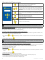
3.1 Description of the Ei² user interface
Increase or reduction the chlorine production:
100 %
20 %
40 %
60 %
80 %
- Activate / deactivate the chlorine production by a short press.
- Switch off the device with a long press (5 seconds).
- Switch on the device with a short press.
H0470400.A - EN - 2014-09
FLOW
Red indicator showing the absence of flow and/or presence of air in the cell.
SALT
Orange indicator showing a water conductivity problem (not enough salt,
water too cold, etc.).
6
3.2 Description of the Ei² Expert user interface
- Exit the user menu or the internal settings menu.
- Deactivate Boost mode or Low mode.
- From the home screen: increase or decrease in chlorine production.
- In the user menu: value changes when a choice is proposed (flashing
characters).
- Simultaneous press for 5 seconds: access the internal settings menu.
- Access to user menu and navigation in the settings (with successive
presses)
- Activate/deactivate the chlorine production by a short press.
- Switch off the device with a long press
- Switch on the device with a short press
and
and
- Activate Boost mode
- Activate "Low" mode manually
If the language displayed on the screen when the Ei² Expert is first switched on is not appropriate, see §3.2.6.
3.2.1 Chlorine production activated
When chlorine production starts, the "Start..." message is displayed on screen for about 6 seconds. "CHLORINATION" is
then displayed, indicating that the device is producing chlorine.
3.2.2 "Boost" mode: chlorine production increased to 100 % for 24 h
In certain cases the pool may need higher than normal chlorination (stormy weather, high number of bathers, etc.).
"Boost" mode is used to increase chlorine level quickly.
• Press buttons
starts.
and
simultaneously: "BOOST" is displayed on the screen and 100 % chlorine production
• To stop "Boost" mode, press
.
When "Boost" mode is activated, the rated chlorine production settings are temporarily overridden and the Ei²
Expert chlorinator will operate for a total of 24 hours at 100 % chlorine production. The number of days will
therefore depend on the Ei² Expert operating times (see §3.2.5).
3.2.3 "Low" mode: chlorine production reduced to 10 % if the pool is covered
If the pool has a covering system (shelter, shutter, cover, etc.), "Low" mode is designed to adapt the chlorine production
to situations where the pool is covered (lower needs). Its effect is to limit chlorine production to 10%.
This mode is also called "Shutter" mode.
Manual activation (shelter, cover, etc.) :
• Press buttons
to 10 %.
and
• To stop "Low" mode, press
simultaneously: "LOW" is displayed on the screen and chlorine production is reduced
.
Automatic activation (compatible electric roll-on shutter):
• Make sure that the shutter is compatible and connected to the Ei² Expert chlorinator (see §2.5.2).
• «Low» mode will automatically be activated when the shutter is closed.
• "Low" mode will stop as soon as the shutter is completely open.
7
H0470400.A - EN - 2014-09
3.2.4 Setting the time
The Ei² Expert chlorinator is fitted with an internal memory. When the device is first switched on it is important
to leave it powered on continuously for at least 24 hours in order to initially charge the accumulator (permanent
separate power supply or filtering on permanently). Once charged the accumulator has several weeks of autonomy
in the event of a power failure.
The time is displayed in a 24 hour format.
• Switch on the device and wait until screen start-up sequence is finished.
• Press the
button to access the user menu, the minutes start to flash.
• Use the
and
buttons to set the minutes, then press
• Use the
and
buttons to set the hours, then press
to store.
to store.
• Press the
button to return to the home screen.
3.2.5 "Summer" and "Winter" modes and setting the "Timers"
"Timer" programming is used to define the device operating times within the filtering system operation times.
The daily operating times must be sufficient to correctly treat the water. Ei² Expert proposes default settings of
Timers 1 and 2. They can be customised (see §3.2.5.b).
A reminder of the calculation rule: the ideal daily filtering time is obtained by dividing the required pool water
temperature (measured in °C) by 2.
Example: for water at 28 °C, time = 28/2 = 14 hours per day
The Ei² Expert chlorinator can store 2 seasonal operating modes called by default "Sum" and "Win". The following
settings can be customised for each mode:
- the device operating times, the "timers": T1 (Timer 1) and T2 (Timer 2)
- the required chlorine production rate: 10 %, 20 %, 30 %,... up to 100 %.
STANDBY = Device operating status
T = "Timer" mode (always active)
SUM = "Summer" operating mode
80 % = chlorine production rate
14:25 = time in 24 h format
3.2.5.a Mode selection: "SUMMER" or "WINTER"
• Press
• Use the
screen.
4 times to set the clock. "SUM" starts to flash.
buttons to choose "SUM" or "WIN" mode, then press the
and
button to return the home
3.2.5.b Programming the timers according to the modes
The times of Timers 1 and 2 cannot overlap. In addition, the time range of Timer 1 necessarily precedes that of
Timer 2.
TE1 / TE2 = Timer in "summer" mode No. 1 / Timer in "summer" mode No. 2
08:00-12:00 = Operating time range of Timer No. 1
14:00-18:00 = Operating time range of Timer No. 2
H0470400.A - EN - 2014-09
8
EN
• Press
4 times to set the clock. "SUM" starts to flash.
• Select the mode to be customised "SUM" or "WIN" using the
move to the timer setting screen.
and
• Use the
and
buttons to set the Timer 1 stop minutes, then press
• Use the
and
buttons to set the Timer 1 stop hours, then press
• Use the
and
buttons to set the Timer 1 start minutes, then press
and
buttons to set the Timer 1 start hours, then press
• Use the
• Repeat the steps for Timer 2.
• Press the
• Use the
buttons, then press
to store and
to store.
to store.
to store.
to store.
button to store the timers and move to setting the chlorine production rate.
and
buttons to choose the required chlorine production rate (from 10 % to 100 %).
3.2.6 "Internal settings" menu
Ei² Expert has an "Internal settings" menu to change and/or view the following operating parameters:
• Language
• Polarity inversion cycles
• Operating hours counter
To access this menu, press the
and
buttons simultaneously for 5 seconds.
EMEA: Device sale and use region (not modifiable)
FR French: Language used (modifiable, by default = French)
Cyc=5h: Polarity inversion cycle (modifiable, by default = 5 h)
00000: Operating hours counter (not modifiable)
3.2.6.a Setting the language
By default the Ei² Expert chlorinator is set to display in French. 13 languages are available: French, English, Spanish,
Italian, Swedish, German, Portuguese, Dutch, Afrikaans, Czech, Hungarian, Slovakian and Turkish.
• From the home screen, press the
• Use the
• Press the
and
and
buttons for 5 seconds. The current language starts to flash.
buttons to select the required language.
button to return to the home screen.
3.2.6.b Polarity inversion
The choice of polarity inversion cycles may affect the cell lifetime (+/- 15 %). Ask your professional reseller for
advice in case of doubt.
9
H0470400.A - EN - 2014-09
Ei² and Ei² Expert are equipped with a polarity inversion system making the cell self-cleaning (default setting = 5
hours).
Ei² Expert offers a choice of 3 inversion cycles:
• 3 hours: for water of high carbonate content (TH > 40 °f or 400 ppm)
• 5 hours: for normal water (20 °f < TH < 40 °f or 200 ppm < TH < 400 ppm)
• 7 hours: for water of low carbonate content (TH < 20 °f or 200 ppm).
• From the home screen, press the
• Press the
• Use the
• Press the
and
buttons for 5 seconds.
button. The polarity inversion cycle hours start to flash.
and
buttons to select the required cycle.
button to return to the home screen.
3.2.6.c Operating hours counter
Ei² Expert can count its total operating hours (= chlorine production time). This information may be useful to
determine the electrode age. The value is provided for information only and may be modified.
• From the home screen, press the
and
buttons for 5 seconds.
• The number of operating hours is displayed at the bottom right of the screen.
• Press the
button to return to the home screen.
EN
4. Maintenance
4.1 Washing the pool filter (backwash)
Ei² and Ei² Expert MUST be switched off when washing the filter. When the device is on (filtration on), press the
button for 5 seconds to switch it off.
button (short press). It will resume
After cleaning the filter, switch the device on again by pressing the
normal operation (production slaved to filtration for Ei² and production according to the Timers set for Ei²
Expert.
The manufacturer cannot be held liable in case of incorrect handling.
4.2 Cleaning the electrode
The Ei² and Ei² Expert are equipped with a smart polarity inversion system designed to prevent the electrode
plates from scaling. However cleaning may be required in regions where the water is very hard.
• Turn off the chlorinator and the filtering, close the isolation valves, remove the protection cover and disconnect the cell
power cable.
• Unscrew the tightening ring and remove the cell. The ring is crenelated thus allowing a lever to be used in the event of
it jamming. Place the cell backwards and fill it with a cleaning solution so that the electrode plates are immersed.
• Leave the cleaning solution to dissolve the scale deposit for about 15 minutes. Dispose of the cleaning solution at an
approved waste recycling site, never pour into the rainwater drainage system or into the sewers.
• Rinse the electrode using clean water and put it back on the cell fixture collar (there is an alignment foolproofer).
• Refit the tightening ring, reconnect the cell cable and refit the protective cover. Open the isolation valves and restart
the filtering and chlorinator.
• If you do not use a commercially available cleaning solution, you can manufacture it yourself by carefully mixing
1 volume of hydrochloric acid with 9 volumes of water (Warning: always pour the acid into the water and not
the opposite and wear suitable protective equipment!).
• Make sure that the setting of the polarity inversion cycles is adapted to the pool water hardness. See paragraph
3.2.6.b to change them.
H0470400.A - EN - 2014-09
10
4.3 Wintering
The chlorinator has a protective system to limit chlorine production under bad operating conditions such as cold
water (winter) or a lack of salt.
• Active wintering = filtering operational in winter: below 10 °C it is preferable to switch off the chlorinator. Above this
temperature you can leave it running.
• Passive wintering = lower water level and drained piping: leave the electrode dry in its cell with its isolation valves open.
5. Troubleshooting
Ei²
Ei²Expert
INVERSION
Possible causes
The self-cleaning cycle is automatic;
this message is not an error code but
an information message.
HIGH SALT
• Salt overload (> 10 g/L).
"Salt"
indicator
on
CHECK SALT
• Lack of salt (< 4g/L) due to water
loss or dilution (filter backwash,
water renewal, rain, leaks, etc.).
• Pool water temperature too low (<
18 °C, variable).
• Cell scaled up or worn.
"Flow"
indicator
on
NO FLOW
• Stop or failure of the filtering
pump.
• Presence of air or gas in the cell
(incorrect filling with water).
• By-pass valves closed.
• Flow controller and/or cell
disconnected or defective.
PUMP
• This message is displayed
CONTROLLER
alternately with "NO FLOW" if the
situation continues.
CELL FAULT
• Short-circuit in the cell or cable
disconnected/badly connected.
• Worn electrode.
OVERHEATING
X
• Device internal temperature over
70 °C.
• Device internal temperature over
80 °C.
• The device no longer stores the
time.
Solutions
• Wait for about 10 minutes and chlorine
production will resume automatically at the
previously set level.
• The 3 central LEDs flash for a few seconds when
polarity inversion is carried out on Ei².
• Drain the pool partially to reduce the salt
concentration.
• Add salt to the pool to keep the level at 4 g/l. If
you do not know the salt level or how to test it,
consult your reseller.
• Basic production limitation signal when the
water is too cold. Reduce chlorine production or
add salt to compensate.
• Clean or replace the cell.
• Check the pump and its programming clock, the
filter, the skimmer(s), and the by-pass valves.
Clean them if necessary.
• Check the cable connections (cell and flow
controller).
• Check that the flow controller is working
correctly (replace it if necessary).
• Perform the same checks as above.
• Check the cell connections.
• Replace the cell.
• Have the control box (electronic board and
transformer) checked by a qualified technician if
necessary.
• The device reduces its production to 50 %.
• Production stops.
• Production restarts automatically when the
temperature drops.
• Check the condition of the accumulator.
• Replace it if necessary (3 V accumulator, type
"CR2032"), see §2.5.2 to open and close the box.
==> If the problem continues contact your reseller.
11
H0470400.A - EN - 2014-09
6. Registering the product
Register your product on our website:
--you will be the first to be informed of new Zodiac® products and special offers,
--you can help us to constantly improve our product quality.
Europe & Rest of the World
www.zodiac-poolcare.com
America
www.zodiacpoolsystems.com
Australia – Pacific
www.zodiac.com.au
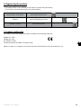
7. Product conformity
This appliance has been designed and built according to the following standards:
EN6000-6-1: 2006
EN6000-6-3: 2007
IEC 61558-2-6: 1997
AS/ NZ 3136-2001 (IEC 60065 + IEC 60335-2-60)
EN
Relative to which it is compliant. The product has been tested under the normal conditions of use.
H0470400.A - EN - 2014-09
12
Pour plus de renseignements, merci de contacter votre revendeur.
For further information, please contact your retailer.
ZODIAC® is a registered trademark of Zodiac International, S.A.S.U., used under license.
Zodiac Pool Care Europe - BP 90023 - 49180 St Barthélémy d’Anjou cedex - S.A.S.U. au capital de 1 267 140 € / SIREN 395 068 679 / RCS PARIS
www.zodiac-poolcare.com
Votre revendeur / your retailer