1
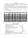
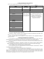
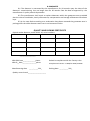
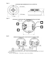
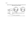
ISO 9001:2008
OPTICAL SMOKE POINT DETECTOR
Model: SPD-3.10
USER’S
MANUAL
Private enterprise "ARTON"
6 Prutska street
Chernivtsi 58008 Ukraine
EN 54-7
For further information please contact us:
+38 0372 584373
www.arton.com.ua
1. FUNCTIONS
1.1 The SPD-3.10 smoke optical point detector is designed to detect smoky fires indoors.
1.2 The detector sets off when small quantities of smoke appear indicating alarm condition and
transmitting alarm signal to a control panel. The detector also has functions of standby mode
indication and checking for proper operation.
1.3 The detector operates with 2-wire and 4-wire fire alarm and fire intruder alarm control
panels all day long. You can connect detectors to a 2-wire CP using B01, B1 bases. You can connect
the detector to a 4-wire CP using B2, B3, B4, and B5 bases. B6, B7, B8, and B9 are end-of-line bases
installed by one at the end of each loop and used in 4-wire loops to control power voltage and
circuit continuity.
1.4 The detector can also be connected to a 4-wire CP using B01, B1 bases as well as MUSH-1,
MUSH-2 and other modules.
1.5 The compatible bases, their features and wiring can be found in Table 1.
Base
Remote
indicator
Relay
B01
B1
B2
B3
B4
B5
B6 (EOL)
B7 (EOL)
B8 (EOL)
B9 (EOL)
+
+
+
+
+
1
1
1
1
2
2
2
2
Relay
contacts of the
base
NC
NO
NC
NO
NO, NC
NO, NO
NO, NC
NO, NO
Table 1
Wiring
2-wire
2-wire
4-wire
4-wire
4-wire
4-wire
4-wire
4-wire
4-wire
4-wire
Note: «+» denotes the presence of the function, «-» denotes its absence;
2 TECHNICAL SPECIFICATIONS
2.1 Technical specifications of the SPD-3.10 with B01 base.
2.1.1 Wiring…………………………………………………………………………2-wire
2.1.2 Supply voltage range, V………………………………………………………10 - 30
2.1.3 Standby current consumption, mA……………………………………………0,10 max
2.1.4 Alarm current consumption, mA …………………………………………….8 - 30
2.1.5 Internal resistance in alarm mode at 20 mA, Ohm…………………………...500 max
2.1.6 Reverse current at minus 30 V voltage, μA…………………………...............5 max
2.1.7 Start-up time, sec………………………….......................................................30 max
2.1.8 Dimensions, mm…………………………........................................................∅85х37
2.1.9 Weight, g…………………………...................................................................150 g
2.1.10 Operating temperature range, °С…………………………............................from - 30 to 55
2.1.11 Meantime-between-failures, h………………………….................................60 000 min
2.1.12 Average lifespan, years…………………………...........................................10 min
2.2 Technical characteristics of the SPD-3.10 detector with the B1-B9 bases.
2.2.1 For technical characteristics of the SPD-3.10 detector with the B1-B9 bases please refer to
the appropriate manuals.
3. ITEMS SUPPLIED WITH THE DETECTOR
3.1 The items supplied with the detector are shown in Table 2.
Name
SPD-3.10 smoke optical detector
Manual
Package
B1 base
Manual
B2 base
Manual
B3 base
Manual
B4 base
Manual
B5 base
Manual
B6 base
Manual
B7 base
Manual
B8 base
Manual
B9 base
Manual
Quantity
Up to 25 pcs.
Table 2
Note
B01 base included
1 pc.
1 pc.
Per 25 detectors
SPD-3.10 detectors can be completed with B1-B9 bases
Quantity and type
of bases depend on
the purchase order
The quantity of bases in one
package corresponds with the
quantity of the detectors.
B1-B9 bases are supplied the
appropriate manuals.
3.2 You can order bases without detectors.
3.3 MUSH-1, MUSH-2 modules can be supplied to connect the detectors with B01 or B1
bases to a 4-wire control panel if specially ordered.
3.4 K-5 mounting rings can be supplied to install detectors onto suspended ceilings if
specially ordered.
4. DESIGN AND PRINCIPLES OF OPERATION
4.1 The detector consists of the detector itself and the base. The optical system, the signal
processing electronic unit and LED control circuit are in the plastic housing of the detector.
4.2 For the appearance, dimensions of the detector, dimensions of the B01 base please refer
to Figure 1, Figure 2.
4.3 The principle of detector’s operation is based on the control of optical medium density.
When exceeding smoke density threshold, the electronic circuit shall issue the alarm signal.
4.4 The standby mode is indicated with the red flashing LED.
4.5 The indication of the fire mode depends on the AL the detector is connected to. The LED
is steadily lit in DC AL, and flashes in AC AL.
4.6. The test button is used to check functions of the detector.
4.7 The B1-B9 bases are constructed the same as B01 base, with the same dimensions (see
Figure 2). The only difference is that auxiliary screw contacts and coordination compartment (closed
with the lid) are fitted on the on the bases for connection to AL. The purpose, view, screw contacts
marking and wiring diagram are shown in the appropriate manuals for bases.
5. HOW TO PREPARE THE DETECTOR FOR OPERATING
5.1 Open the package after receiving detectors, check contents.
ATTENTION! If detectors were in below 0o C temperature conditions before opening the
package, allow them to acclimatize inside the structure for at least 4 hours.
5.2 Test detectors for proper operating.
5.2.1 Connect a base to a DC power source of 20-30 V and ≥50 mA load current (“plus”
connect to the contact “1”, “minus” – to the contact “8”). Fit a current limiting resistor between
contacts “8” and “7”. The resistance value of the limiting resistor specifies the alarm current
consumption in the detector circuit according to p. 2.6. The recommended resistance value is 100
Ohm for 12 V, and - 680 Ohm for 24 V.
ATTENTION! Connection to above 12 V power source without a resistor limiting current at 30
mA is PROHIBITED.
5.2.2 Connect the electronic unit to the base.
5.2.3 Energize the detector. The detector shall go to standby mode, the red LED flashes shall
indicate about. Leave the detector in that condition for at least 30 sec.
5.2.4 Check the voltage on the contacts “1” and “2” of the base relatively to the contact “8”
with a DC voltmeter. The difference of the voltages should not be more than 0.1 V.
5.2.5 Press the test button and keep it pressed for at least 10 sec. In not more than 10 sec
the detector shall go to the alarm mode, steady light of the red LED indicates about.
5.2.6 Deenergize the detector for at least 3 sec. The red LED shall be off.
5.2.7 Repeat p.5.2.3.
5.2.8 Insert into the test hole on the detector’s cover (a plastic or metal pin Ø0,9 mm, 40-50
mm long) for at least 10 sec. In not more than 10 sec. the detector shall go to the alarm mode.
5.2.9 Deenergize the detector. The LED shall be on.
6. LOCATION AND INSTALLATION
6.1 You should l detectors in places with the following conditions:
-minimal vibrations of constructions;
-minimal illumination intensity;
-maximum distance from sources of electrical-magnetic interferences (electric wiring etc.), infrared radiation (heat devices);
-elimination of water ingress on the case and penetration out of the base;
-no gas, steam, aerosol emission that can cause corrosion.
6.2 You should provide protection against construction debris and dusts when repairing lodgings.
6.3 Detectors are connected to a loop with the help of bases. It is possible to connect up to three
≤0,5 mm2 wires to one screw joint of the base.
6.4 It is recommended to install detectors onto suspended ceilings with K-5 mounting ring.
6.5 The wiring diagrams for detectors with B01 base to control panels are shown in Figure 3Figure 6.
6.6 For wiring diagrams for detectors with the B1-B9 bases to control panels please refer to the
appropriate manuals.
7. MAINTENANCE
7.1 Vacuum at least every six months to keep the unit working efficiently by turning off the
mains supply first and vacuuming through the vents during one minute using a soft brush
attachment or using another 0,5-3 kg/cm2 compressor.
7.2 Then test detectors for proper operating.
7.3 The test can be made either by pressing the test button or inserting a tester-pin into the
hole on the detector’s head (see p. 5.2.8). The red LED will be lit when the detector operates
properly, and the control panel will issue the alarm signal.
8. GUARANTEE
8.1 The detector is warranted by the manufacturer for 18 months upon the date of the
detector’s commissioning but not longer than for 30 months from the date of approval by the
manufacturer’s quality control department.
8.2 The manufacturer shall repair or replace detectors within the guarantee term provided
that the rules of installation, timely maintenance, transportation and storage of detectors have been
kept.
8.3 In the case faults according to a reclamation have been removed the guarantee term is
prolonged for the while detectors were not in use because of faults.
QUALITY AND PACKING CERTIFICATE
Optical smoke detector, model SPD-3.10, serial numbers:
_________________pieces
With B01 base______________pieces
With B__base_______________pieces
Manufacturing date
__ __.__ __.201_
Quality control mark____________________
Packed in compliance with the factory rules
Compliant with EN 54 – 7:2000/А1:2002/А2:2006
Packing date __ __.__ __.201_
Figure 1
Figure 2
APPEARANCE AND DIMENSIONS OF SPD-3.10 DETECTOR
APPEARANCE, DIMENSIONS AND CONTACTS NUMERATION OF B01 BASE
7
2
8
1
Figure 3
WIRING DIAGRAM FOR SPD-3.10 WITH B01 TO DC CONTROL PANEL
For 24 V: CLR = (0,36–2) kOhm, EOL resistor - from 2,4 to 10 kOhm depending on the control
panel specifications.
For 12 V: CLR=≤620 Ohm, EOL resistor – from 1,2 to 6,2 kOhm.
Figure 4
WIRING DIAGRAM FOR SPD-3.10 WITH B01 TO CONTROL PANEL
TO INCREASE FALSE ALARM IMMUNITY
EOL resistor and CLR correspond to Figure 1.
Capacitors С i – ceramic 0,1 – 0,22 µF; C EOL – 22 µF 25 V
Figure 5
WIRING DIAGRAM FOR SPD-3.10 WITH B01 TO AC CONTROL PANEL
AL with current limited at 20 mA.
Diode VD EOL type 1N4148, EOL resistor 3.9 kOhm 0,25 W
Figure 6
WIRING DIAGRAM FOR SPD-3.10 WITH B01 TO FIRE-INTRUDER CONTROL PANEL
THROUGH MUSH-1 MODULE (MUSH-2)
R N resistor –1,5 kOhm 0,25 W.
EOL resistor is specified by control panel specifications (from 1 to 10 kOhm)