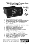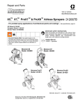
1
PD8 Series ProtEX-MAX Supplemental Instruction Manual Modern, Sleek and Practical Enclosure Display Mountable at 0°, 90°, 180°, & 270° Degrees Explosion-Proof, IP68, NEMA 4X Enclosure PROVU®, Trident X2, or Vigilante® II Functionality SafeTouch® Through-Glass Button Programming Flanges for Wall or Pipe Mounting Modbus® RS-485 Serial Communications Standard on Most Models Free MeterView® and MeterView® Pro Software All Models Include Sunlight Readable Displays PRECISION DIGITAL CORPORATION 89 October Hill Road • Holliston MA 01746 USA Tel (800) 343-1001 • Fax (508) 655-8990 www.predig.com PD8 Series Explosion-Proof Instrument Supplemental Manual Disclaimer The information contained in this document is subject to change without notice. Precision Digital makes no representations or warranties with respect to the contents hereof; and specifically disclaims any implied warranties of merchantability or fitness for a particular purpose. ! CAUTION: Read complete instructions prior to installation and operation of the instrument. WARNING: Risk of electric shock or personal injury. WARNING • This product is not recommended for life support applications or applications where malfunctioning could result in personal injury or property loss. Anyone using this product for such applications does so at his/her own risk. Precision Digital Corporation shall not be held liable for damages resulting from such improper use. • Failure to follow installation guidelines could result in death or serious injury. Make sure only qualified personnel perform the installation. • Never remove the instrument cover in explosive environments when the circuit is live. • Cover must be fully engaged to meet flameproof/explosion-proof requirements. • Information in this manual supersedes all enclosure, compliance, and agency approval information included in additional product manuals included with this product. Limited Warranty Precision Digital Corporation warrants this product against defects in material or workmanship for the specified period under “Specifications” from the date of shipment from the factory. Precision Digital’s liability under this limited warranty shall not exceed the purchase value, repair, or replacement of the defective unit. Registered Trademarks All trademarks mentioned in this document are the property of their respective owners. © 2011-2015 Precision Digital Corporation. All rights reserved. www.predig.com 2 PD8 Series Explosion-Proof Instrument Supplemental Manual INTRODUCTION The ProtEX-MAX has been designed to offer the functions and features of any PROVU, Trident X2, or Vigilante II model in a great looking full-approved explosionproof product. The PD8 series is not just a 1/8 DIN meter mounted in an explosionproof housing; a special bezel and electronics were designed exclusively for the ProtEX-MAX. The bezel and faceplate give the front panel a very finished appearance and house the additional electronics for the PD8. The user has the ability to program and operate the instrument without opening the housing using the built-in SafeTouch through-glass button programming or serial communications port with free Modbus protocol included (serial communications not present on PD8-154 or PD8-158 Series models). How to Use this Manual This ProtEX-MAX includes this manual addendum and a complete panel meter instruction manual for a PROVU, Trident X2, or Vigilante II. This manual addendum combines with the additional included manual to provide you complete product information. This manual contains all the information on the ProtEX-MAX enclosure, SafeTouch through-glass button programming, and the on-board functions that may include RS-485 serial communications, digital inputs, digital outputs, and other features not included in the base model. These features have electrical wiring connections on the round board mounted to the rear of the electronics housing.. ! NOTICE Information in this manual supersedes all enclosure, compliance, and agency approval information included in additional product manuals included with this product. For information on programming your product, the user interfaces, or general instrument specifications, please refer to the PROVU, Trident X2, or Vigilante II instruction manual included with this ProtEX-MAX. Example: A PD8-6000-6H2 will include this manual as well as the PD6000 PROVU instruction manual (LIM6000). Refer to the PROVU PD6000 manual for all setup, programming, and most electronics specifications. Refer to this manual for operation of the SafeTouch through-glass button programming, on-board RS-485 connections, digital inputs/outputs, enclosure information, and all approvals. ! For PD8-6xxx/7xxx models only: Transmitter supplies rated @ 25 mA max each NOTICE 3 PD8 Series Explosion-Proof Instrument Supplemental Manual MODEL NUMBER DESCRIPTIONS Model Description Integrated Functionality PD8-154 4 Point Alarm Annunciator Vigilante II PD154 PD8-158 8 Point Alarm Annunciator Vigilante II PD158 PD8-765 Large Display Universal Input Meter Trident X2 PD765 PD8-6000 Process Meter PROVU PD6000 PD8-6060 Dual-Input Process Meter PROVU PD6060 PD8-6080 Modbus Serial Input Scanner PROVU PD6080 PD8-6081 Feet & Inches Modbus Serial Input Scanner PROVU PD6081 PD8-6100 Strain Gauge Meter PROVU PD6100 PD8-6200 Analog Input Rate/Totalizer PROVU PD6200 PD8-6210 Analog Input Batch Controller PROVU PD6210 PD8-6262 Dual Analog Input Batch Controller PROVU PD6262 PD8-6300 Pulse Input Rate/Totalizer PROVU PD6300 PD8-6310 Pulse Input Batch Controller PROVU PD6310 PD8-6363 Dual Pulse Input Rate/Totalizer PROVU PD6363 PD8-7000 Temperature Meter PROVU PD7000 Ordering Configuration Example The model number of a PD8 Series ProtEX-MAX is in the format of PD8- followed by the numeric model number of the product whose features the ProtEX-MAX shares. Note that only “H” SunBright display models are available ProtEX-MAX models with integrated PROVU functionality. Example: A PD8-6000-6H2 is the model number of a dual-line process meter with the features and options of a PD6000-6H2; all PD6000 PROVU features with AC line power, 2 relays, and a SunBright sunlight readable display. PROVU Based Configuration Example PD8 6 0 0 0 6 H 2 Any PROVU SunBright Display Model Trident X2 Based Configuration Example PD8 7 6 5 6 X 2 - 1 - 1 Any Trident X2 Model Vigilante II Based Configuration Example PD8 1 5 4 6 R 2 Any Vigilante II Model 4 0 PD8 Series Explosion-Proof Instrument Supplemental Manual Table of Contents INTRODUCTION ---------------------------------------------------------------------- 3 MODEL NUMBER DESCRIPTIONS --------------------------------------------- 4 Ordering Configuration Example -------------------------------------------------------- 4 SPECIFICATIONS -------------------------------------------------------------------- 7 Instrument Specifications ----------------------------------------------------------------- 7 General ------------------------------------------------------------------------------------------- 7 Serial Communications --------------------------------------------------------------------- 7 Digital Inputs & Outputs -------------------------------------------------------------------- 8 External Switch Contacts ------------------------------------------------------------------ 8 Product Ratings and Approvals; -------------------------------------------------------- 9 COMPLIANCE INFORMATION ---------------------------------------------------------- 10 Safety ------------------------------------------------------------------------------------------- 10 Electromagnetic Compatibility --------------------------------------------------------- 10 SAFETY INFORMATION ---------------------------------------------------------- 11 INSTALLATION ---------------------------------------------------------------------- 11 Unpacking ------------------------------------------------------------------------------------- 12 Pre-Installed Conduit/Stopping Plug ------------------------------------------------- 12 Mounting --------------------------------------------------------------------------------------- 12 Cover Jam Screw --------------------------------------------------------------------------- 12 CONNECTIONS ---------------------------------------------------------------------- 13 Required & Factory Wired Connections -------------------------------------------- 13 Digital I/O Connections ------------------------------------------------------------------- 18 External Switch Contacts ---------------------------------------------------------------- 19 Serial Communications Connections ------------------------------------------------ 21 Using PROVU Serial Adapters ----------------------------------------------------------- 24 OPERATION -------------------------------------------------------------------------- 25 Overview --------------------------------------------------------------------------------------- 25 ® SafeTouch Buttons ----------------------------------------------------------------------- 25 Digital I/O -------------------------------------------------------------------------------------- 26 Serial Communications Overview----------------------------------------------------- 26 TROUBLESHOOTING ------------------------------------------------------------- 28 Troubleshooting Tips---------------------------------------------------------------------- 28 SERVICE ------------------------------------------------------------------------------- 29 MOUNTING DIMENSIONS -------------------------------------------------------- 30 EC DECLARATION OF CONFORMITY --------------------------------------- 31 5 PD8 Series Explosion-Proof Instrument Supplemental Manual Table of Figures Figure 1: Integrated Vigilante II (PD8-154-6 & PD8-158-6) Required Connections...................................................................................... 14 Figure 2: Integrated Vigilante II (PD8-154-7 & PD8-158-7) Required Connections...................................................................................... 15 Figure 3: Integrated Trident X2 (PD8-765) Required Connections ....... 16 Figure 4: Integrated PROVU Required Connections ............................... 17 Figure 5: Digital I/O Connections ............................................................ 18 Figure 6: External Switch Contacts ........................................................ 20 Figure 7: ProtEX-MAX Connections to a Serial Converter ................... 21 Figure 8: RS-485 Wiring ........................................................................... 22 Figure 9: RS-485 Two-Wire Multi-Drop Wiring ....................................... 23 Figure 10: General Four-Wire Network Connection .............................. 27 Figure 11: General Two-Wire Network Connection ............................... 27 Figure 12: Enclosure Dimensions – Front View .................................... 30 Figure 13: Enclosure Dimensions – Side Cross Section View ............. 30 6 PD8 Series Explosion-Proof Instrument Supplemental Manual SPECIFICATIONS Except where noted all specifications apply to operation at +25°C. Instrument Specifications Refer to the data sheet and manual for the meter/controller integrated to the PD8. General CONNECTIONS Screw terminals accept 12 to 22 AWG wire ENCLOSURE Explosion-proof die cast aluminum with glass window, corrosion resistant epoxy coating, color: blue. NEMA 4X, 7, & 9, IP68. Default conduit connections: Four ¾" NPT threaded conduit openings and two ¾" NPT metal conduit plugs with 12 mm hex key fitting installed. Additional conduit opening configurations may be available; verify quantity and sizes on specific device labeling during installation. MOUNTING Four slotted flanges for wall mounting or NPS 1½" to 2½" or DN 40 to 65 mm pipe mounting. See Mounting Dimensions on page 30. OVERALL DIMENSIONS 6.42" x 7.97" x 8.47" (W x H x D) (163 mm x 202 mm x 215 mm) APPROXIMATE SHIPPING WEIGHT 16.0 lbs (7.26 kg) WARRANTY 3 years parts and labor Serial Communications These specifications are not applicable to PD8-154 and PD8-154 series, which have no serial communications. COMPATIBILITY CONNECTORS MAX DISTANCE EIA-485 Removable screw terminal connector 3,937' (1,200 m) max STATUS INDICATION Separate LEDs for Power (P), Transmit (TX), and Receive (RX) 7 PD8 Series Explosion-Proof Instrument Supplemental Manual Digital Inputs & Outputs Note: PD8 Series PROVU integrated functionality models only. See notices and warnings on page 18. CHANNELS SYSTEM 4 digital inputs & 4 digital outputs per module One expansion module may be added for a total of 8 inputs & 8 outputs Note: The jumper located between the RJ45 connectors must be removed on the expansion module. DIGITAL INPUT LOGIC HIGH 3 to 5 VDC DIGITAL INPUT LOGIC LOW 0 to 1.25 VDC DIGITAL OUTPUT LOGIC HIGH 3.1 to 3.3 VDC DIGITAL OUTPUT LOGIC LOW 0 to 0.4 VDC SOURCE CURRENT 10 mA maximum output current SINK CURRENT 1.5 mA minimum input current To be used as pull-up for digital inputs only. Connect normally open pushbuttons across +5 V & DI 1-4. +5 V TERMINAL DO NOT use +5 V terminal (pin 1) to power external devices. WARNING External Switch Contacts PD8-765 Series Trident X2 integrated functionality models only. See Vigilante II Instruction Manual for information on PD8-154 and PD8-158 Series external switch contact specifications. Open State +5 VDC open contact on switch input terminals Closed State Closed contact switch input terminal to common/ground, active low 0 to 0.4 VDC, or open collector transistor activated input 8 PD8 Series Explosion-Proof Instrument Supplemental Manual Product Ratings and Approvals; FM Enclosure: Type 4X; IP66 Class I, Division 1, Groups B, C, D Class II, Division 1, Groups E, F, G Class III, Division 1, T5/T6 Class I, Zone 1, AEx d, IIC Gb T5/T6 Zone 21, AEx tb IIIC T90°C; Ta -40°C to +65°C T6 Ta = -40°C to +60°C; T5 Ta = -40°C to +65°C Certificate Number: 3047283 CSA Class I, Division 1, Groups B, C, D Class II, Division 1, Groups E, F, G Class III, Division 1 Class I Zone 1 Ex d IIC Zone 21 Ex tb IIIC T90°C -40°C < Tamb. < +60° C; Temperature Code T6 -40°C < Tamb. < +65° C; Temperature Code T5 Enclosure Type 4X & IP66 Certificate Number: 2531731 ATEX II 2 G D Ex d IIC T* Gb Ex tb IIIC T90°C Db IP68 Ta = -40°C to +*°C *T6 = -40°C to +60°C *T5 = -40°C to +65°C Certificate number: Sira 12ATEX1182 IECEx Ex d IIC T* Gb Ex tb IIIC T90°C Db IP68 Ta = -40°C to +*°C *T6 = -40°C to +60°C *T5 = -40°C to +65°C Certificate Number: IECEx SIR 12.0073 Special Conditions for Safe Use: Use suitably certified and dimensioned cable entry device and/or plug. The equipment shall be installed such that the supply cable is protected from mechanical damage. The cable shall not be subjected to tension or torque. If the cable is to be terminated within an explosive atmosphere, then appropriate protection of the free end of the cable shall be provided. Cable must be suitable for 90°C. Year of Construction This information is contained within the serial number with the first four digits representing the year and month in the YYMM format. For European Community: The ProtEX-MAX must be installed in accordance with the ATEX directive 94/9/EC, and the product certificate Sira 12ATEX1182. 9 PD8 Series Explosion-Proof Instrument Supplemental Manual COMPLIANCE INFORMATION Safety LOW VOLTAGE DIRECTIVE EN 61010-1:2010 Safety requirements for measurement, control, and laboratory use Electromagnetic Compatibility EMISSIONS Radiated Emissions AC Mains Conducted Emissions IMMUNITY RFI - Amplitude Modulated Electrical Fast Transients Electrostatic Discharge RFI - Conducted AC Surge Surge Power-Frequency Magnetic Field Voltage Dips Voltage Interruptions EN 55022:2010 Class A ITE emissions requirements Class A Class A EN 61326-1:2006 Measurement, control, and laboratory equipment EN 61000-6-2:2005 EMC heavy industrial generic immunity standard 80 -1000 MHz 10 V/m 80% AM (1 kHz) 1.4 - 2.0 GHz 10 V/m 80% AM (1 kHz) 2.0 - 2.7 GHz 10 V/m 80% AM (1 kHz) ±2 kV AC mains, ±1kV other ±4 kV contact, ±8kV air 10 V, 0.15-80 MHz, 1kHz 80% AM ±2 kV Common, ±1kV Differential 1 kV (CM) 3 A/m 70%V for 0.5 period 40% V for 5 & 50 periods 70% V for 25 periods <5% V for 250 periods 10 PD8 Series Explosion-Proof Instrument Supplemental Manual SAFETY INFORMATION WARNINGS Read complete instructions prior to installation and operation of the instrument. Installation and service should be performed only by trained service personnel. Service requiring replacement of internal sub-components must be performed at the factory. Disconnect from supply before opening enclosure. Keep cover tight while circuits are alive. Conduit seals must be installed within 18" (450mm) of the enclosure or within 2" (50mm) for Zone installations. Verify that the operating atmosphere of the instrument is consistent with the appropriate hazardous locations certifications. If the instrument is installed in a high voltage environment and a fault or installation error occurs, high voltage may be present on any lead Read all product labels completely and follow all instructions and requirements listed on the labels for installation or service. INSTALLATION Install in accordance with applicable local and national regulations (e.g. NEC). For Installation in USA: The ProtEX-MAX must be installed in accordance with the National Electrical Code (NEC) NFPA 70. For Installation in Canada: The ProtEX-MAX must be installed in accordance with the Canadian Electrical Code CSA 22.1. All power supplies below 36 V and input circuits must be derived from a CSA Approved Class 2 source. For European Community: The ProtEX-MAX must be installed in accordance with the ATEX directive 94/9/EC and the product certificate Sira 12ATEX1182. Disconnect from supply before opening enclosure. Keep cover tight while circuits are alive. Conduit seals must be installed within 18" (450mm) of the enclosure or within 2" (50mm) for Zone WARNING installations. Wiring connectors are accessed by opening the enclosure. To access electrical connectors, remove the 2 captive screws and then remove the electronics module. Connectors are on the rear of the electronics module. 11 PD8 Series Explosion-Proof Instrument Supplemental Manual Unpacking Remove the instrument from packing box. Inspect the packaging and contents for damage. Report damages, if any, to the carrier. If any part is missing or the instrument malfunctions, please contact your supplier or the factory for assistance. Pre-Installed Conduit/Stopping Plug The PD8 Series is supplied with two pre-installed conduit plugs for installations that do not require the use of all conduit entries. The conduit/stopping plugs include an internal 12mm hexagonal socket recess for removal. The pre-installed plugs and their installation are included in the hazardous area approvals for the PD8 Series enclosure. In hazardous areas, conduit and conduit/stopping plugs require the application of non-setting (solvent free) thread sealant. It is critical that all relevant hazardous area guidelines be followed for the WARNING installation or replacement of conduit or plugs. Mounting The ProtEX-MAX Series has four slotted mounting flanges that should be used for pipe mounting or wall mounting. Refer to Mounting Dimensions, page 30 for details. Do not attempt to loosen or remove flange bolts while the instrument is in service. WARNING Cover Jam Screw The cover jam screw should be properly installed once the instrument has been wired and tested in a safe environment. The cover jam screw is intended to prevent the removal of the instrument cover in a flameproof environment without the use of tools. Using a M2 hex wrench, turn the screw clockwise until the screw contacts the aluminum enclosure. Turn the screw an additional 1/4 to 1/2 turn to secure the cover. Caution: Excess torque may damage the threads and/or wrench. 12 PD8 Series Explosion-Proof Instrument Supplemental Manual CONNECTIONS WARNINGS Static electricity can damage sensitive components. Observe safe handling precautions for static-sensitive components. Use proper grounding procedures/codes. If the instrument is installed in a high voltage environment and a fault or installation error occurs, high voltage may be present on any lead or terminal. Follow all fusing and wiring precautions requirements for the instrument integrated to the PD8 Series model number being connected. To access the connectors, remove the enclosure cover and unscrew the two captive screws that fasten the electronics module. Signal connections are made to depluggable connectors on the back of the electronics module. Some connectors may be provided already connected. These connections are required for proper operation of the ProtEX-MAX, and should not be removed unless instructed to by this manual. Wires marked as being used for testing purposes should be removed. Grounding connections are made to the two ground screws provided on the base – one internal and one external. After all connections have been completed and verified, apply power to the unit. Required & Factory Wired Connections The ProtEX-MAX comes with several pre-wired connections. These connections are detailed below, and must be maintained in order for the instrument to function properly. For details on the required wiring to maintain basic ProtEX-MAX functions, refer to the appropriate below section for the specific ProtEX-MAX model number. Observe all safety regulations. Electrical wiring should be performed in accordance with all agency requirements and applicable national, state, and local codes to prevent damage to the meter WARNING and ensure personnel safety. 13 PD8 Series Explosion-Proof Instrument Supplemental Manual Required Connections on PD8-154-6 and PD8-158-6 Series Models ProtEX-MAX units with Vigilante II integrated functionality have two factory wired connectors. Four wires connect the remote switch inputs of the annunciator. Two wires connect the DC power supply on the main meter electronics to the ProtEX-MAX connector board. These must remain connected as shown for the SafeTouch Buttons to function on these models. ! The connections described in this section must remain connected for the SafeTouch buttons to function. NOTICE Figure 1: Integrated Vigilante II (PD8-154-6 & PD8-158-6) Required Connections 14 PD8 Series Explosion-Proof Instrument Supplemental Manual Required Connections on PD8-154-7 and PD8-158-7 Series Models Low voltage PD8-154-7 and PD8-158-7 models require low voltage power to be supplied to the power supply connector on the ProtEX-MAX connector board as well as to the integrated Vigilante II connections as described in the Vigilante II Instruction Manual. In addition, four wires connect the remote switch inputs of the annunciator to the ProtEX-MAX connector board. These wires must remain connected for the SafeTouch buttons to function. ! The connections described in this section must remain connected for the SafeTouch buttons to function. NOTICE Figure 2: Integrated Vigilante II (PD8-154-7 & PD8-158-7) Required Connections 15 PD8 Series Explosion-Proof Instrument Supplemental Manual Required Connections on PD8-765 Series Models ProtEX-MAX units with Trident X2 integrated functionality have two factory wired connectors. A modular cable must connect from the rear of the integrated Trident X2 electronics to the ProtEX-MAX connector board. The Trident X2 integrated models also have a 5 position external switch connector wired from the rear of the integrated Trident X2 electronics to the ProtEX-MAX connector board as shown below. This must remain connected as shown to the ProtEX-MAX connector board for the SafeTouch Buttons to function on these models. ! The connections described in this section must remain connected for the SafeTouch buttons to function. NOTICE Figure 3: Integrated Trident X2 (PD8-765) Required Connections 16 PD8 Series Explosion-Proof Instrument Supplemental Manual Required Connections on PD8-6000, PD8-6060, PD8-6080, PD8-6081, PD8-6100, PD8-6200, PD8-6210, PD8-6300, PD8-6310, and PD8-7000 Series Models One factory installed M-LINK cable connects the integrated PROVU electronics to the ProtEX-MAX connector board. Figure 4: Integrated PROVU Required Connections 17 PD8 Series Explosion-Proof Instrument Supplemental Manual Digital I/O Connections ProtEX-MAX models with integrated PROVU functionality have a 10 position terminal block for connecting the digital inputs and outputs. See Model Number Descriptions on page 4 for details on ProtEX-MAX integrated instruments. 1 2 3 4 5 6 7 8 9 10 +5 I1 I2 I3 I4 O1 O2 O3 O4 G 5 VDC DI 1-4 DO 1-4 GND Figure 5: Digital I/O Connections (PROVU Integrated Instruments Only) ! NOTICE The digital inputs are configured at the factory to function identically to the front panel pushbuttons in order to work with the SafeTouch buttons. Changing the programming of the digital inputs will affect the function of the SafeTouch buttons. Observe all safety regulations. Electrical wiring should be performed in accordance with all agency requirements and applicable national, state, and local codes to prevent damage to the meter WARNING and ensure personnel safety. 18 PD8 Series Explosion-Proof Instrument Supplemental Manual External Switch Contacts ProtEX-MAX models with integrated Vigilante II, PROVU, or Trident X2 may be wired with external switch contacts. See Model Number Descriptions on page 4 for details on ProtEX-MAX integrated instruments. For Vigilante II Integrated Functionality Instruments The ProtEX-MAX includes a removable screw terminal connector with external switch contacts. See the Vigilante II instruction manual for more information on connecting these external switch contacts. For PROVU Integrated Functionality Instruments The ProtEX-MAX includes 4 digital inputs. These digital inputs are preconfigured at the factory to function as external contacts to duplicate the front button functions of the instrument. The factory configuration uses the following corresponding digital input terminals for external switch contacts. Digital Input Connection I1 I2 I3 I4 Factory Default Function MENU RIGHT arrow UP arrow ENTER arrow See Digital Inputs & Outputs in the Specification on page 8 for details on the digital inputs. ! NOTICE The digital inputs are configured at the factory to function identically to the front panel pushbuttons in order to work with the SafeTouch buttons. Changing the programming of the digital inputs will affect the function of the SafeTouch buttons. 19 PD8 Series Explosion-Proof Instrument Supplemental Manual For Trident X2 Integrated Functionality Instruments The ProtEX-MAX includes a removable screw terminal connector for external switch contacts. External switch contacts may be wired across the switch contact and COM on the connector labeled Trident X2 External Switch Connections in the Figure below. Figure 6: External Switch Contacts (Trident X2 Integrated Instruments Only) ! NOTICE Removing the connectors or changing the default wiring of the ProtEX-MAX external switch connectors will affect the function of the SafeTouch buttons. See External Switch Contacts in the Specification on page 8 for electrical specifications for using the external switch contacts. 20 PD8 Series Explosion-Proof Instrument Supplemental Manual Serial Communications Connections ProtEX-MAX instruments with integrated PROVU and Trident X2 functionality have a 5 position terminal block for connecting RS-485 serial devices. See Model Number Descriptions on page 4 for details on ProtEX-MAX integrated instruments. Vigilante II integrated models do not have serial communications. Figure 7 details the wiring connections from the ProtEX-MAX to an RS-485 serial converter (such as the PDA7485 or PDA8485) for a four-wire network. ProtEX-MAX to RS-485 Serial Converter Connections RS-485 Serial Converter ProtEX-MAX RS-485 Connections DO DI DO DI DI DO DI DO Figure 7: ProtEX-MAX Connections to a Serial Converter (PROVU & Trident X2 Integrated Instruments Only) Baud rates are adjustable and handled by the PROVU or Trident X2 (see the included manuals for more details on programming the serial communications settings). The ProtEX-MAX has three diagnostic LEDs: a Power (P) LED to show when the module is powered properly, a Transmit Data (TX) LED to show when the module is being transmitted to by the PC side, and a Receive Data (RX) LED to show when the module is sending data to a receiving device. The following diagrams detail how to connect the RS-485 serial communications from the ProtEX-MAX to a RS-485/RS-232 serial converter (PDA7485) in four wire and two wire configurations. 21 PD8 Series Explosion-Proof Instrument Supplemental Manual Figure 8: RS-485 Wiring Notes: 1. 2. 3. Termination resistors are optional and values depend on the cable length and characteristic impedance. Consult the cable manufacturer for recommendations. Refer to RS-232 to RS-485 Converter documentation for further details. Use shielded cable, twisted-pairs plus ground. Connect ground shield only at one location. Observe all safety regulations. Electrical wiring should be performed in accordance with all agency requirements and applicable national, state, and local codes to prevent damage to WARNING the meter and ensure personnel safety. 22 PD8 Series Explosion-Proof Instrument Supplemental Manual Figure 9: RS-485 Two-Wire Multi-Drop Wiring Notes: 1. 2. 3. Termination resistors are optional and values depend on the cable length and characteristic impedance. Consult the cable manufacturer for recommendations. Refer to RS-232 to RS-485 Converter documentation for further details. Use shielded cable, twisted-pair plus ground. Connect ground shield only at one location. Observe all safety regulations. Electrical wiring should be performed in accordance with all agency requirements and applicable national, state, and local codes to prevent damage to WARNING the meter and ensure personnel safety. When using more than one instrument in a multi-drop or multi-point mode, each meter must be provided with its own unique address. Refer to the PROVU or Trident X2 instruction manual included with this ProtEX-MAX for information on how to change the communication address. 23 PD8 Series Explosion-Proof Instrument Supplemental Manual Using PROVU Serial Adapters ! NOTICE PROVU expansion modules and serial adapters are not included in the hazardous area approvals of the ProtEX-MAX. The PDA1232 and PDA8008 may be used only while the ProtEX-MAX is in a safe area, and will disable some features while installed. PROVU expansion modules and serial adapters are not recommended for use with the ProtEX-MAX. It is recommended that any serial protocol conversion required on the RS-485 communications connection be performed using a PDA7485 RS-232 to RS-485 or PDA8485 USB to RS-485 serial converter located in a safe area. 24 PD8 Series Explosion-Proof Instrument Supplemental Manual OPERATION Overview The following instructions detail the operation of features specific to the ProtEX-MAX. For information on using the features of the integrated meter or controller, including instrument programming, configuration, input, output, or display features, see the PROVU, Trident X2, or Vigilante II instruction manual. Setup and programming may be done through the infrared through-glass SafeTouch buttons, or using the mechanical buttons when uncovered. There is a slide switch located on the connector board. This is used to enable or disable SafeTouch Buttons. SafeTouch® Buttons The ProtEX-MAX is equipped with four sensors that operate as through-glass buttons so that it can be programmed and operated without removing the cover (and exposing the electronics) in a hazardous area. These buttons can be disabled for security by selecting DISABLE on the switch labeled NO-CONTACT BUTTONS located on the connector board. To actuate a button, press one finger to the glass directly over the marked button area. Then retract finger more than three inches from the glass before pressing the next button. When the cover is removed, the four mechanical buttons located next to the sensors are used. The sensors are disabled when a mechanical button is pressed and will automatically be re-enabled after 60 seconds of inactivity. The SafeTouch Buttons are designed to filter normal levels of ambient interference and to protect against false triggering, however, it is recommended that the SafeTouch Buttons be disabled (slide switch to LOCK) if there is an infrared interference source in line-of-sight to the display. The SafeTouch Buttons are configured by default to duplicate the function of the front panel mechanical pushbuttons associated with the integrated meter. The symbols by each SafeTouch button correspond to a mechanical button. Operation of the instrument is performed as described in the PROVU, Trident X2, or Vigilante II instruction manual included with the ProtEX-MAX. SafeTouch Button Tips: To the extent possible, install the display facing away from sunlight, windows, reflective objects and any sources of infrared interference. Keep the glass window clean. Tighten the cover securely. Use a password to prevent tampering. Take caution when cleaning the window glass as it may result in unintentional SafeTouch button events. Only clean the ProtEX-MAX when the system is safely shut down, and inspect WARNING the ProtEX-MAX for proper configuration prior to system restart. 25 PD8 Series Explosion-Proof Instrument Supplemental Manual Digital I/O Digital inputs and outputs are only present on ProtEX-MAX models with integrated PROVU functionality. See Model Number Descriptions on page 4 for details on which instruments qualify. The ProtEX-MAX has four digital inputs and four digital outputs. External digital inputs can function similarly to the front panel function keys. ! NOTICE The digital inputs are configured at the factory to function identically to the front panel pushbuttons in order to work with the SafeTouch buttons. Changing the programming of the digital inputs will affect the function of the SafeTouch buttons. They can be configured to trigger certain events (i.e. acknowledge/reset alarms, reset max and/or min values, disable/enable all output relays, and hold current relay states), provide direct menu access point, or mimic front panel keys. Digital outputs can be used to remotely monitor alarm relay output states, or the states of a variety of actions and functions executed by the meter. See the PROVU Instruction Manual included with this instrument for details on programming the Digital I/O. Serial Communications Overview RS-232 and RS-485 are standard interfaces approved by the Electronic Industries Alliance (EIA) for connecting serial devices. In EIA terms, the device (e.g. meter) that connects to the interface is called a Data Communications Equipment (DCE) and the device to which it connects (e.g. the computer) is called a Data Terminal Equipment (DTE). RS-485 can support multi-point connections per line because it uses lowerimpedance drivers and receivers. Line drivers and receivers are used to exchange data between two or more points (nodes) on a serial communications network. Reliable data communications can be difficult in the presence of induced noise, ground level differences, and other hazards associated with installation of a network. When communicating at high data rates, or over long distances in real world environments, RS-232 is often inadequate. The differential data transmission of RS-485 offers superior performance in most applications. Differential signals can help nullify the effects of ground shifts and induced noise signals that can appear as common mode voltages on a network. A multi-point network consists of multiple drivers and receivers connected on a single bus, where any point (node) can transmit and/or receive data. RS-485 allows multiple drivers and receivers on the same two-wire or four-wire system. The RS-485 standard specifies up to 32 drivers and 32 receivers on a single bus, but with the 26 PD8 Series Explosion-Proof Instrument Supplemental Manual introduction of "automatic" repeaters and high-impedance drivers/receivers, this number can be extended to hundreds of points (nodes) on a network. The cabling used for an RS-485 serial communications network should always be a high quality cable such as Belden 8162 or Alpha 6203C. A two-wire system requires two twisted pairs, and a four-wire system requires three twisted pairs (the extra twisted pair is needed for the signal ground). Figure 10 illustrates how to connect a general four-wire network (a four-wire network actually contains 5 wires). PDA8485 RS-485 DEVICE GND DO DO DI DI GND DI DI DO DO Figure 10: General Four-Wire Network Connection Figure 11 illustrates how to connect a general two-wire network (a two-wire network actually contains 3 wires). Note that the PDA7485 and PDA8485 have DIP switches that allow for two-wire connections without the need to externally wire the DO to the DI and the /DO to the /DI (see the converter section for complete details). PDA8485 RS-485 DEVICE GND DATA DATA GND DO DO DI DI Figure 11: General Two-Wire Network Connection 27 PD8 Series Explosion-Proof Instrument Supplemental Manual TROUBLESHOOTING The ProtEX-MAX rugged design should make it unusual for the installer or operator to refer to this section of the manual. If the instrument is not working as expected, refer to the recommendations below. Troubleshooting Tips Symptom SafeTouch buttons do not respond Check/Action If mechanical button was pushed. The SafeTouch buttons will be re-enabled automatically 60 seconds after the last button push. If slide switch on connector board is in DISABLE position, switch to ENABLE. Strong direct sunlight may interfere with SafeTouch button operation. It is recommended to operate the buttons by standing so as to block direct sunlight. Serial Communications Power LED Indicator is off 1. Check modular cable connection 2. Check power to the device 1. Check serial cable 2. Check protocol selected on device 3. Check instrument address & baud rate 4. Check program address & baud rate 1. Check serial cable 2. Check protocol selected on device 3. Check instrument address & baud rate 4. Check program address & baud rate Remove all unnecessary cables and instruments from the bus. Try getting the system to work with only one device (to ease troubleshooting) and then expand the system one device at a time. Increase the baud rate 1. Increase the TX delay time 2. Decrease the baud rate 1. Check modular cable connection 2. Check power to instrument Call Technical Support for assistance or the instruction manual included with this ProtEX-MAX. Meter not communicating with MeterView, MeterView Pro, or other programs If only the TX (or DATA IN) data status LED is flashing when serial communications attempted If both data status LEDs (TX and RX) are off when trying to communicate Communications slow Random communication errors Power LED is off Other symptoms not described above 28 PD8 Series Explosion-Proof Instrument Supplemental Manual SERVICE WARNINGS Installation and service should be performed only by trained service personnel. Service requiring replacement of internal sub-components must be performed at the factory. Disconnect from supply before opening enclosure. Keep cover tight while circuits are alive. Conduit seals must be installed within 18" (450mm) of the enclosure. Verify that the operating atmosphere of the instrument is consistent with the appropriate hazardous locations certifications. If the instrument is installed in a high voltage environment and a fault or installation error occurs, high voltage may be present on any lead Read all product labels completely and follow all instructions and requirements listed on the labels for installation or service. If the enclosure is sound and undamaged, then only the internal electronics housing will need to be returned to the factory for service. Contact the factory for RMA number and return instructions. 29 PD8 Series Explosion-Proof Instrument Supplemental Manual MOUNTING DIMENSIONS All units: inches (mm) Figure 12: Enclosure Dimensions – Front View Figure 13: Enclosure Dimensions – Side Cross Section View 30 PD8 Series Explosion-Proof Instrument Supplemental Manual EC DECLARATION OF CONFORMITY Issued in accordance with ATEX Directive 94/9/EC Manufacturer: Device: Notified Body: Precision Digital Corporation 89 October Hill Rd Ste 5 Holliston, MA 01746 USA PD8 Series Device Sira Certification Service, notified body no. 0518 Rake Lane, Eccleston, Chester, CH4 9JN, England EC Type Examination Certificate: Quality Assurance Notification No.: Sira 12ATEX1182 SIRA 10 ATEX M462 Compliance with Standards: Product Markings: EN 60079-0:2009 EN 60079-1:2007 EN 60079-31:2008 EN 61326:2006 IEC 61010-1:2010 & EN61010-1:2010, including Group and National Differences as they apply for AU, CA, and US II 2GD Ex d IIC T* Gb Ex tb IIIC T90°C Db IP68 Ta = -40°C to +*°C *T6 = -40°C to +60°C *T5 = -40°C to +65°C The standard EN 60079-0:2009 is no longer harmonized. The requirements of this standard have been checked against the harmonized standard EN 60079-0:2012 and there were no major technical changes affecting the latest technical knowledge for the products listed above. Community Directives: 94/9/EC ATEX Directive 2004/108/EC EMC Directive Name: Company: Title: Date: Jeffrey Peters Precision Digital Corporation President 08/01/2014 31 PD8 Series Explosion-Proof Instrument Supplemental Manual How to Contact Precision Digital For Technical Support: Call: (800) 610-5239 or (508) 655-7300 Fax: (508) 655-8990 Email: [email protected] For Sales Support: Call: (800) 343-1001 or (508) 655-7300 Fax: (508) 655-8990 Email: [email protected] For the latest version of this manual please visit: www.predig.com LIM8_H 03/15