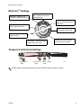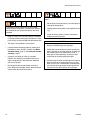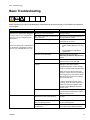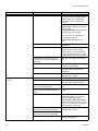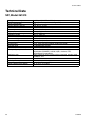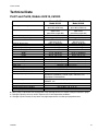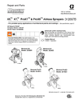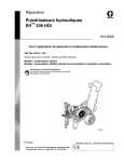
1
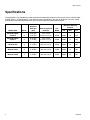
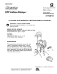
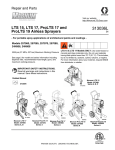
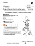
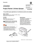
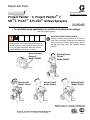
Repair and Parts
Visit our website;
http://MAGNUM.Graco.com
Project Painter™ 5, Project Painter™ 7,
SR™7, ProX7™ & ProX9™ Airless Sprayers
312004B
- For portable spray applications of architectural paints and coatings (See specifications, page 2.)
IMPORTANT SAFETY INSTRUCTIONS.
Read all warnings and instructions in this manual.
Save these instructions. See page 2 for model and
series information including dispense rate, recommended hose length, guns, and maximum working
pressure.
Project Painter 5 and Project Painter 7 ONLY. Use
water based or mineral-spirit type material only. Do
not use materials having flash points lower than 70°F
(21°C). For more information about your material
request MSDS from distributor or retailer.
MAGNUM Project
Painter 5
Model: 261800
MAGNUM Project
Painter 7
Model: 261805
ti9195a
ti9194a
MAGNUM SR7
Model: 261810
ti9193a
MAGNUM ProX7
Model: 261815
ti9369a
Graco Inc. P.O. Box 1441 Minneapolis, MN 55440-1441
Copyright 2007, Graco Inc. is registered to I.S. EN ISO 9001
MAGNUM ProX9
Model: 261820
ti9368a
Specifications
Specifications
This equipment is not intended for use with flammable or combustible materials used in places such as cabinet shops
or other “factory”, or fixed locations. If you intend to use this equipment in this type of application, you must comply
with NFPA 33 and OSHA requirements for the use of flammable and combustible materials.
2
Maximum Working
Pressure
Model Name
Series
Dispense
Rate gpm
(lpm)
MAGNUM Project
Painter 5
A
0.24 gpm
(0.91 lpm)
1/4 in. x 25 ft
(6.4 mm x 7.5 m)
SG10
2800
19
193
MAGNUM Project
Painter 7
A
0.31 gpm
(1.17 lpm)
1/4 in. x 35 ft
6.4 mm x. 11 m)
SG10
3000
21
207
MAGNUM SR7
A
0.31 gpm
(1.17 lpm)
1/4 in. X 35 ft
(6.4 mm x 11 m)
SG10
3000
21
207
MAGNUM ProX7
A
0.34 gpm
(1.28 lpm)
1/4 in. X 50 ft
(6.4 mm x 15 m)
SG20
3000
21
207
MAGNUM ProX9
A
0.38 gpm
(1.44 lpm)
1/4 in. X 50 ft
(6.4 mm x 15 m)
SG20
3000
21
207
Hose Length and
Diameter
Gun
Model
PSI
MPa
bar
312004B
Warnings
Warnings
The following warnings are for the setup, use, grounding, maintenance, and repair of this equipment. The exclamation point symbol alerts you to a general warning and the hazard symbols refer to procedure-specific risks. Refer
back to these warnings. Additional, product specific warnings may be found throughout the body of this manual
where applicable.
WARNING
FIRE AND EXPLOSION HAZARD
Flammable fumes, such as solvent and paint fumes, in work area can ignite or explode. To help prevent
fire and explosion:
• Use equipment only in well ventilated area.
• Eliminate all ignition sources; such as pilot lights, cigarettes, portable electric lamps, and plastic drop
cloths (potential static arc).
• Sprayer generates sparks. When flammable liquid is used in or near the sprayer or for flushing or
cleaning, keep sprayer at least 20 feet (6 m) away from explosive vapors.
• Keep work area free of debris, including solvent, rags and gasoline.
• Do not plug or unplug power cords or turn lights on or off when flammable fumes are present.
• Ground equipment and conductive objects in work area. Read Grounding instructions.
• If there is static sparking or you feel a shock, stop operation immediately. Do not use equipment
until you identify and correct the problem.
• Keep a fire extinguisher in the work area.
ELECTRIC SHOCK HAZARD
Improper grounding, setup, or usage of the system can cause electric shock.
• Turn off and disconnect power cord before servicing equipment.
• Use only grounded electrical outlets.
• Use only 3-wire extension cords.
• Ensure ground prongs are intact on sprayer and extension cords.
• Do not expose to rain. Store indoors.
SKIN INJECTION HAZARD
High-pressure fluid from gun, hose leaks, or ruptured components will pierce skin. This may look like just
a cut, but it is a serious injury that can result in amputation. Get immediate surgical treatment.
• Do not point gun at anyone or at any part of the body.
• Do not put your hand over the spray tip.
• Do not stop or deflect leaks with your hand, body, glove, or rag.
• Engage trigger lock when not spraying.
• Follow Pressure Relief Procedure in this manual, when you stop spraying and before cleaning,
checking, or servicing equipment.
312004B
3
Warnings
WARNING
EQUIPMENT MISUSE HAZARD
Misuse can cause death or serious injury.
• Do not exceed the maximum working pressure or temperature rating of the lowest rated system
component. Read Technical Data in all equipment manuals.
• Use fluids and solvents that are compatible with equipment wetted parts. Read Technical Data in all
equipment manuals. Read fluid and solvent manufacturer’s warnings. For complete information
about your material, request MSDS from distributor or retailer.
• Check equipment daily. Repair or replace worn or damaged parts immediately with genuine Graco
replacement parts only.
• Do not alter or modify equipment.
• Use equipment only for its intended purpose. Call your Graco distributor for information.
• Route hoses and cables away from traffic areas, sharp edges, moving parts, and hot surfaces.
• Do not kink or overbend hoses or use hoses to pull equipment.
• Comply with all applicable safety regulations.
• Keep children and animals away from work area.
• Do not operate the unity when fatigued or under the influence of drugs or alcohol.
PRESSURIZED ALUMINUM PARTS HAZARD
Do not use 1,1,1-trichloroethane, methylene chloride, other halogenated hydrocarbon solvents or fluids
containing such solvents in pressurized aluminum equipment. Such use can cause serious chemical
reaction and equipment rupture, and result in death, serious injury, and property damage.
TOXIC FLUID OR FUMES HAZARD
Toxic fluids or fumes can cause serious injury or death if splashed in the eyes or on skin, inhaled, or
swallowed.
• Read MSDS’s to know the specific hazards of the fluids you are using.
• Store hazardous fluid in approved containers, and dispose of it according to applicable guidelines.
PERSONAL PROTECTIVE EQUIPMENT
You must wear appropriate protective equipment when operating, servicing, or when in the operating
area of the equipment to help protect you from serious injury, including eye injury, inhalation of toxic
fumes, burns, and hearing loss. This equipment includes but is not limited to:
• Protective eye wear
• Clothing and respirator as recommended by the fluid and solvent manufacturer
• Gloves
• Hearing protection
4
312004B
Installation
Installation
Grounding and Electric
Requirements
Fluid supply container: follow local code.
Sprayer must be grounded. Grounding reduces the risk
of static and electric shock by providing an escape wire
for electrical current due to static build up or in the event
of a short circuit.
Grounding the metal pail: connect a ground wire to the
pail by clamping one end to pail and other end to ground
such as a water pipe.
•
This sprayer requires
a 120 Vac, 60 Hz,
15A circuit with a
grounding receptacle.
•
Never use an outlet
that is not grounded
or an adapter.
•
•
Solvent pails used when flushing: follow local code.
Use only conductive metal pails, placed on a grounded
surface such as concrete. Do not place the pail on a
nonconductive surface, such as paper or cardboard,
which interrupts grounding continuity.
Maintaining grounding
continuity when flushing or
relieving pressure: hold metal
part of the spray gun firmly to
the side of a grounded metal
pail, then trigger the gun.
ti5573a
ti9207a
Do not use the sprayer if the
electrical cord has a damaged
ground prong.
Thermal Overload
Only use an extension cord with
an undamaged 3-prong plug.
ti5572a
Recommended extension cords
for use with this sprayer:
• 50 ft (15.0 m) 16 AWG (1.0 mm2)
• 100 ft (30.0 m) 14 AWG (1.5 mm2)
Spray gun: ground through connection to a properly
grounded fluid hose and pump.
Motor has a thermal overload switch to shut itself down
if overheated. If unit overheats, allow approximately 45
minutes for unit to cool. Once cool, switch will close and
unit will restart.
To reduce risk of injury from motor starting unexpectedly when it cools, always turn power switch OFF if
motor shuts down.
Smaller gauge or longer extension cords may
reduce sprayer performance.
312004B
5
Component Identification
Component Identification
Project Painter 5
A
AllControl™
•
•
•
•
•
•
B
Pump fluid outlet fitting
Threaded connection for paint hose.
C
Suction tube
Draws fluid from paint pail or hopper into pump.
D
Prime tube (with diffuser)
Drains fluid in system during priming and pressure relief.
E
Inlet screen
Prevents debris from entering pump.
E1
Inlet screen handle
Aids in the installation and removal of the inlet screen.
F
Hopper cover
Prevents debris from entering hopper.
G
Pour spouts
Directs paint out of hopper and back into paint container.
H
Hopper
2.5 gal. (9.5 L) capacity hopper that holds paint.
J
Tip holder
Storage for 2 spray tips.
K
Hopper handle
Press and turn handle to allow access to hopper and paint
tray.
L
Paint tray
Built in paint tray to rest roller attachment when not in use.
M
Disposable hopper liner
Fits directly in hopper and is disposable for simple cleanup.
N
Practice Spray Board
Instructs user on how to perform basic spraying techniques
and provides surface to practice techniques prior to spraying
surfaces.
P
Power Flush™ attachment
Connects garden hose to suction tube for power flushing
water-base fluids.
R
Paint hose
Transports high-pressure fluid from pump to spray gun.
S
Airless spray gun
Dispenses fluid.
T
Tip guard
Reduces risk of fluid injection injury.
U
Reversible spray tip
•
•
6
STORAGE: for long term or overnight shutdown and storage.
OFF: turns motor off for short term shutdown and
relieves system pressure.
PRIME/CLEAN PUMP: turns on motor and directs fluid
to prime tube.
ROLL: directs low pressure fluid to roller (when used)
PRIME/CLEAN GUN & HOSE: directs fluid to gun and
hose.
LOW SPRAY to HIGH SPRAY: directs fluid to spray gun.
Atomizes fluid being sprayed, forms spray pattern and
controls fluid flow according to hole size.
When reversed, unclogs plugged tips without disassembly.
V
Gun fluid filter
Filters fluid entering spray gun to reduce tip clogs.
W
Roller attachment
Attaches to spray gun for pressure rolling directly on
surfaces.
X
Gun trigger safety lever (page 14)
Prevents accidental triggering of spray gun.
312004B
Component Identification
G
E1
F
G
M
E
ti9305a
L
D
ti9533a
K
ti9374a
S
T
H
U
X
ti9301a
J
ti9306a
A
B
R
P
ti9208a
ti9168a
W
ti9724a
V
ti10257a
N
ti9257a
C
ti9294a
Bottom view and position for direct immersion mode
312004B
7
Component Identification
Component Identification
Project Painter 7
A
AllControl™
•
•
•
•
•
•
B
Pump fluid outlet fitting
Threaded connection for paint hose.
C
Suction tube
Draws fluid from paint pail into pump.
D
Prime tube (with diffuser)
Drains fluid in system during priming and pressure relief.
E
Inlet screen
Prevents debris from entering pump.
F
Pail hanger
For transporting pail by its handle.
G
Roller tray/Gun holder/Hose Wrap
Removable tray can also be used to clean paint roller.
H
Quick Release Latch
Collapses handle for compact or hanging storage.
J
Storage compartment
Provides onboard storage for spray tips and/or tools.
L
Sample spray shield
Introduces benefits of a spray shield. Blocks paint from surfaces you do
not want to spray.
M
SpillGuard™ tray
Protective tray to set sprayer and paint pail on during operation.
N
Practice spray board
Instructs user on how to perform basic spraying techniques and provides
surface to practice techniques prior to spraying surfaces.
P
Power Flush™ attachment
Connects garden hose to Suction tube for power flushing water-base
fluids.
R
Paint hose
Transports high-pressure fluid from pump to spray gun.
S
Airless spray gun
Dispenses fluid.
T
Tip guard
Reduces risk of fluid injection injury.
U
Reversible spray tip
•
•
8
STORAGE: for long term and overnight shutdown and storage.
OFF: turns motor off for short term shutdown and relieves system
pressure.
PRIME/CLEAN PUMP: turns on motor and directs fluid to prime
tube.
ROLL: directs low pressure fluid to roller (when used)
PRIME/CLEAN GUN & HOSE: directs fluid to gun and hose.
LOW SPRAY to HIGH SPRAY: directs fluid to spray gun.
Atomizes fluid being sprayed, forms spray pattern and controls fluid
flow according to hole size.
When reversed, unclogs plugged tips without disassembly.
V
Gun fluid filter
Filters fluid entering spray gun to reduce tip clogs.
W
Roller attachment
Attaches to spray gun for pressure rolling directly on surfaces.
X
Gun trigger safety lever (page 14)
Prevents accidental triggering of spray gun.
312004B
Component Identification
L
P
G
M
ti9724a
ti9312a
H
ti9307a
B
ti9310a
F
J
D
ti9309a
W
A
C
E
ti10257a
ti9168a
N
U
S
T
R
ti9257a
V
X
ti9208a
312004B
9
Component Identification - SR7
Component Identification - SR7
A
Power Switch
Turns sprayer ON and OFF.
B
Prime/Spray Valve
•
•
•
PRIME position (pointing down) directs fluid to prime tube.
SPRAY position (pointing forward) directs pressurized fluid to paint
hose.
Automatically relieves system pressure in overpressure situations.
C
Pressure control knob
Increases (clockwise) and decreases (counter-clockwise) fluid pressure
in pump, hose and spray gun.
C1
Setting Indicator
To select function, align symbol on pressure control knob with setting
indicator, page 15.
D
Pump fluid outlet fitting
E
™
InstaClean
fluid filter
Threaded connection for paint hose.
•
•
Filters fluid coming out of pump to reduce tip plugging and improve
finish.
Self cleans only during pressure relief.
Pressurizes fluid and delivers it to paint hose. Easy Access door permits
quick removal of outlet valve.
F
Power-Piston
Access door)
G
Suction tube
Draws fluid from paint pail into pump.
H
Prime tube (with diffuser)
Drains fluid in system during priming and pressure relief.
J
Sample Spray Shield
Introduces benefits of a spray shield. Blocks paint from surfaces you do
not want to spray.
L
Inlet screen
Prevents debris from entering pump.
M
Storage compartment
Provides onboard storage for spray tips and/or tools.
N
Quick Release Latch
Collapses handle for compact or hanging storage.
P
Roller tray/Gun holder/Hose wrap
Removable tray can also be used to clean paint roller.
R
Paint hose
Transports high-pressure fluid from pump to spray gun.
Q
Roller attachment
Used with spray gun to apply coating directly to surfaces.
S
Airless spray gun
Dispense fluid through spray tip or roller attachment.
T
Tip guard
Reduces risk of fluid injection injury.
U
Reversible spray tip
•
™
Pump (behind Easy
•
Atomizes fluid being sprayed, forms spray pattern and controls fluid
flow according to hole size.
Reverse unclogs plugged tips without disassembly.
V
Gun trigger safety lever (page 14)
Prevents accidental triggering of spray gun.
W
SpillGuard™ Tray
Protective tray to set sprayer and paint pail on during operation.
X
Practice spray board
Instructs user on how to perform basic spraying techniques and provides
surface to practice techniques prior to spraying surfaces.
Y
Power Flush attachment
Connects garden hose to suction tube for power flushing water-base
fluids.
Z
Gun fluid filter
Filters fluid entering spray gun to reduce tip clogs.
10
312004B
Component Identification - SR7
P
/.
ti9763a
/&&
A
N
B
B
ti9951a
F
D
M
E
H
ti9950a
ti9213a
G
J
L
C
C1
S
U
T
W
V
ti9312a
X
ti10008a
ti9257a
Z
R
ti9208a
ti9724a
Y
312004B
Q
ti10257a
11
Component Identification ProX7 & ProX9
Component Identification ProX7 & ProX9
A
Airless spray gun
Dispenses fluid.
B
Power switch
Turns sprayer ON and OFF.
C
Pressure control knob
Increases (clockwise) and decreases (counter-clockwise) fluid pressure
in pump, hose, and spray gun.
C1
Setting Indicator
To select function, align symbol on pressure control knob with setting
indicator, page 15.
D
Pump fluid outlet fitting
Threaded connection for paint hose.
E
InstaClean™ fluid filter
•
•
Filters fluid coming out of pump to reduce tip plugging and improve
finish.
Self cleans only during pressure relief.
F
ProX Power-Piston Pump (behind Easy
Access door, not shown)
Pumps and pressurizes fluid and delivers it to paint hose.
F1
Easy Access door
Easy Access door permits quick access to outlet valve. To remove door,
insert flat blade of screwdriver into slot on the bottom of the door (as
shown on page 13).
G
Suction tube
Draws fluid from paint pail into pump.
H
Prime tube (with diffuser)
Drains fluid in system during priming and pressure relief.
J
Prime/Spray valve
•
•
™
•
In PRIME position (pointing down) directs fluid to prime tube.
In SPRAY position (pointing forward) directs pressurized fluid to paint
hose.
Automatically relieves system pressure in overpressure situations.
K
Storage compartment
Provides onboard storage for spray tips and/or tools.
L
Inlet screen
Prevents debris from entering pump.
M
Paint hose
Transports high-pressure fluid from pump to spray gun.
Used to fold cart frame for hanging on wall.
N
Fold-n-Store
P
Practice Spray Board
Instructs user on how to perform basic spraying techniques and provides
surface to practice techniques prior to spraying surfaces.
Q
Tip guard
Reduces risk of fluid injection injury.
R
Reversible spray tip
•
™
Handle
•
Atomizes fluid being sprayed, forms spray pattern and controls fluid
flow according to hole size.
Reverse unclogs plugged tips without disassembly.
S
Gun trigger safety lever (page 14)
Prevents accidental triggering of spray gun.
T
Gun fluid inlet fitting
Threaded connection for paint hose.
U
Power Flush attachment
Connects garden hose to suction tube for power flushing water-base
fluids.
V
Gun fluid filter
Filters fluid entering spray gun to reduce tip clogs.
W
Hose wrap bracket
Stows paint hose.
X
Pail hanger
For transporting pail by its handle.
Protective tray to set sprayer and paint pail on during operation.
Y
SpillGuard
Z
Sample spray shield
Introduces benefits of a spray shield. Blocks paint from surfaces you do
not want to spray.
AA
QuickAccess™ Inlet
Permits quick access to inlet valve to clear debris (ProX9 only).
12
™
tray
312004B
Component Identification ProX7 & ProX9
Z
ti9724a
ti9346a
Y
U
ti9312a
B
W
K
J
F
F1
N
ti9670a
H
X
C
G
C1
ti9368a
AA
L
ti9669a
E
D
P
R
S
A
Q
V
T
M
ti9667a
ti9668a
312004B
13
General Repair Information
General Repair Information
1. Turn power switch OFF and unplug
power cord.
ti2018a
Trigger Lock
Always engage the trigger lock when you stop spraying
to prevent the gun from being triggered accidentally by
hand or if dropped or bumped.
Trigger Locked
2. Turn Prime/Spray valve to
PRIME to relieve pressure.
Trigger Unlocked
ti9346a
3. Hold gun firmly to side
of pail. Trigger the gun
to relieve pressure.
ti8923a
SG10 Gun
SG10 Gun
ti8922a
ti9207a
4. Engage trigger lock.
ti8908a
ti8908a
SG20 Gun
ti8909a
SG20 Gun
Pressure Relief Procedure
Follow this Pressure Relief Procedure whenever you
stop spraying and before cleaning, checking, servicing,
or transporting equipment.
14
ti8923a
Leave Prime/Spray valve in the PRIME position
until you are ready to spray again.
If you suspect the spray tip or hose is clogged or that
pressure has not been fully relieved after following the
steps above, VERY SLOWLY loosen tip guard retaining
nut or hose end coupling to relieve pressure gradually,
then loosen completely. Clear hose or tip obstruction.
Read Unclogging Spray Tip instructions in the Sprayer
or Gun Operation manual.
312004B
General Repair Information
AllControl™ Settings
STORAGE - long term and
overnight shutdown and storage
OFF - turns motor off for short
term shutdown and relieves
system pressure
PRIME/CLEAN PUMP - turns
motor on and directs fluid to
prime tube
HI SPRAY - uses high pressure
to direct fluid to spray gun
ROLL - directs low pressure
fluid to roller (when used)
SETTING INDICATOR selects function
LOW SPRAY - uses low pressure
to direct fluid to spray gun
PRIME/CLEAN GUN & HOSE directs fluid to gun and hose
Pressure Control Knob Settings
High Pressure
Spray
Low Pressure
Spray
Prime/ Rolling
Clean
TIA
To select function, align symbol on pressure control knob with setting indicator on sprayer.
312004B
15
General Repair Information
To reduce risk of serious injury, including electric
shock:
Flammable materials spilled on hot, bare, motor
could cause fire or explosion. To reduce risk of burns,
fire or explosion, do not operate sprayer with cover
removed.
•
Keep all screws, nuts, washers, gaskets, and electrical fittings removed during repair procedures. These
parts usually are not provided with replacement kits.
•
Test repairs after problems are corrected.
•
If sprayer does not operate properly, review repair
procedure to verify you did it correctly. See Basic
Troubleshooting, page 17 and Advanced Troubleshooting, page 21.
•
•
16
Overspray may build up in the air passages.
Remove any overspray and residue from air passages and openings in the enclosures whenever
you service sprayer.
Do not operate the sprayer without the cover in
place. Replace if damaged. Covers direct cooling air
around motor to prevent overheating.
•
Do not touch moving or electric pars with fingers or
tools while testing repair.
•
Unplug sprayer when power is not required for testing.
•
Install all covers, gaskets, screws and washers
before you operate sprayer.
CAUTION
• Do not run sprayer dry for more than 30 seconds.
Doing so could damage pump packings.
• Protect the internal drive parts of this sprayer from
water. Openings in the cover allow for air cooling of
the mechanical parts and electronics inside. If
water gets in these openings, the sprayer could
malfunction or be permanently damaged.
• Prevent pump corrosion and damage from freezing.
Never leave water or water-base paint in sprayer
when its not in use in cold weather. Freezing fluids
can seriously damage sprayer. Store sprayer with
Pump Armor to protect sprayer during storage.
312004B
Basic Troubleshooting
Basic Troubleshooting
Check everything in this Basic Troubleshooting Table before you bring the sprayer to a Graco/MAGNUM authorized
service center.
Problem
Project Painter 5 and Project Painter 7 AllControl is on and sprayer is plugged in,
but motor does not run, and pump does
not cycle, or motor continues to run in
OFF position.
Cause
Solution
Project Painter 5 and Project Painter 7 AllControl is set at zero pressure.
Turn AllControl clockwise to increase
pressure setting.
SR7, ProX7 and ProX9 - Pressure is set
at zero pressure.
Turn Pressure Control Knob clockwise to
increase pressure setting.
Motor or control is damaged.
Take sprayer to Graco/MAGNUM
authorized service center.
Electric outlet is not providing power.
•
Try a different outlet or plug in a compatible working appliance to test outlet.
•
Reset building circuit breaker or
replace fuse.
or
SR7, ProX 7 and ProX9 - Power Switch is
on and sprayer is plugged in, but motor
does not run, and pump does not cycle.
Extension cord is damaged.
Replace extension cord. Read
Grounding and Electric Requirements,
page 5.
Sprayer electric cord is damaged.
Check for broken insulation or wires.
Replace electric cord if damaged.
Paint and/or water is frozen or hardened
in pump.
Unplug sprayer from outlet. If frozen do
NOT try to start sprayer until it is
completely thawed or you may damage
the motor, control board and/or drivetrain.
Make sure power switch is OFF. Place
sprayer in a warm area for several hours.
Then plug in power cord and turn sprayer
ON. Slowly increase pressure setting to
see if motor will start.
If paint is hardened in sprayer, pump
packings, valves, drivetrain or pressure
switch may need to be replaced. Take
sprayer to Graco/MAGNUM authorized
service center.
Pump does not prime.
312004B
System is already pressurized.
Turn AllControl to OFF, pause 2-3 seconds and then turn AllControl to STORAGE to relieve pressure.
Project Painter 5 and Project Painter 7 AllControl not set to correct function.
Turn AllControl to PRIME/CLEAN PUMP
position.
SR7, ProX7 and ProX9 - Prime/Spray
Valve is in SPRAY position.
Turn Prime/Spray Valve to PRIME
position (pointing down).
Inlet screen is clogged or suction tube is
not immersed.
Clean debris off inlet screen and make
sure suction tube is immersed in fluid.
17
Basic Troubleshooting
Problem
Pump does not prime.
Cause
Inlet valve check ball is stuck.
Solution
Remove suction tube and place a pencil
into the inlet section to dislodge the ball,
allowing pump to prime properly. OR
Power Flush sprayer (see Operation
manual).
AutoPrime may need replacement. For
Project Painter 7: plug in unit and listen
for “tap” in pump.
SR7 and ProX7 and 9: turn power switch
ON and listen for “tap” in pump.
If you do not hear “tap”, AutoPrime is
damaged. Take sprayer to
Graco/MAGNUM authorized service
center.
Pump cycles but does not build up
pressure.
Inlet valve check ball or seat is dirty.
Remove inlet housing. Clean or replace
ball and seat.
Outlet valve check ball is stuck.
Insert screw driver in slot and remove
Easy-Access™ door, page 10, SR7
models or page 12, ProX7 and ProX9
models. Unscrew outlet valve with a 3/4
in. socket. Remove and clean assembly.
Project Painter 5 and Project Painter 7 In immersion mode suction tube is not
immersed
Make sure suction tube is immersed in
paint.
Suction tube is leaking.
Tighten suction tube connection. Inspect
for cracks or vacuum leaks.
Pump does not prime with fluid.
Remove suction tube from paint. Prime
pump with water or solvent-based
flushing fluid.
AllControl is damaged.
Take sprayer to Graco/MAGNUM
authorized service center.
Pump is not primed.
Prime pump (see Operation manual).
Inlet screen is clogged.
Clean debris off inlet screen and make
sure suction tube is immersed in fluid.
All models in Immersion Mode, suction
tube is not immersed in paint.
Make sure suction tube is immersed in
paint.
Project Painter 5 - Hopper mode or all
models in immersion mode, paint pail is
empty.
Refill hopper or paint pail. Reprime
sprayer.
Suction tube is leaking.
Project Painter 5 (hopper mode): Inlet
tube fitting improperly or not securely
attached to hopper elbow fitting.
Project Painter 7, SR7, ProX 7 and 9:
Tighten suction tube connection. Inspect
for cracks or vacuum leaks. If cracked or
damaged, replace suction tube.
Project Painter 5 and 7 - AllControl prime Take sprayer to Graco/MAGNUM
authorized service center.
valve is worn or obstructed with debris.
SR7, ProX7 and ProX9 - Prime/Spray
Valve is worn or obstructed with debris.
Pump check ball is stuck.
18
Read Pump does not prime section in
Troubleshooting, page 17
312004B
Basic Troubleshooting
Problem
Pump cycles, but paint only dribbles or
spurts when spray gun is triggered.
Cause
Pressure is set too low.
Solution
Project Painter 5 and Project Painter 7
Sprayers -Slowly turn AllControl to HI
SPRAY to increase pressure setting
or
SR7, ProX 7 and ProX9 - Turn Pressure
Control Knob clockwise to increase
pressure setting which will turn on motor
to build pressure.
Spray tip is clogged.
Unclog spray tip (see Operation manual).
SR7, ProX7 and ProX9 - InstaClean fluid Clean or replace InstaClean fluid filter
filter is clogged.
(see Operation manual).
Pressure is set at maximum but cannot
achieve a good spray pattern.
Spray gun fluid filter is clogged.
Clean or replace gun fluid filter (see
Operation manual).
Spray tip is too large or worn.
Replace spray tip.
Reversible spray tip is in UNCLOG
position.
Rotate arrow-shaped handle on spray tip
so it points forward in SPRAY position
(see Operation manual).
Spray tip is too large for sprayer.
Select smaller spray tip.
Spray tip is worn beyond capability of
sprayer.
Replace spray tip.
Extension cord is too long or not heavy
enough gauge.
Replace extension cord. Grounding and
Electrical Requirements, page 5.
Spray gun fluid filter is clogged.
Clean or replace spray gun fluid filter (see
Operation manual).
SR7, ProX7 and ProX9 - InstaClean fluid Clean or replace InstaClean fluid filter
filter is clogged.
(see Operation manual).
Spray gun stopped spraying.
312004B
Inlet screen is clogged.
Clean debris off inlet screen.
Pump valves are worn.
Check for worn pump valves.
a. Prime sprayer with paint
b. Trigger gun momentarily. When
trigger is released, pump should
cycle momentarily and stop. If
pump continues to cycle, pump
valves may be worn. Take
sprayer to Graco/MAGNUM
authorized service center.
Material too thick.
Thin material.
Hose too long (if extra section is added).
Remove section of hose.
Pump was not primed with flushing fluid.
Remove suction tube from paint. Prime
pump with water or flushing
solvent-based flushing fluid.
Suction tube is leaking.
Tighten suction tube connection. Inspect
for cracks or vacuum leaks.
SR7, ProX7 and ProX9 - Prime/Spray
Valve is plugged.
Clean/replace prime tube as necessary.
Take sprayer to Graco/MAGNUM
authorized service center if valve is
plugged.
Spray tip is clogged.
Unclog spray tip (see Operation manual).
19
Basic Troubleshooting
Problem
When paint is sprayed, it runs down the
wall or sags.
Cause
Coat is going on too thick.
Solution
Move gun faster.
Choose a tip with smaller hole size.
Choose tip with wider fan.
Make sure gun is far enough from
surface.
When paint is sprayed, coverage is
inadequate.
Paint coating is going on too thin.
Move gun slower.
Choose tip with larger hole size.
Choose tip with narrower fan.
Make sure gun is close enough to
surface.
Fan pattern varies dramatically while
spraying.
SR7, ProX7 and ProX9 - Pressure control Take sprayer to Graco/MAGNUM
switch is worn and causing excessive
authorized service center.
pressure variation.
OR
Sprayer does not turn on promptly when
resuming spraying.
Cannot trigger spray gun.
Spray gun trigger lock is locked.
Rotate trigger safety lever to unlock
trigger lock, page 14.
Paint is coming out of pressure control
switch.
SR7, ProX7 and ProX9 - Pressure control Take sprayer to Graco/MAGNUM
switch is worn.
authorized service center.
Prime/Spray valve actuates automatically System is over pressurizing.
relieving pressure through prime tube.
Take sprayer to Graco/MAGNUM
authorized service center.
Paint leaks down outside of pump.
Pump packings are worn.
Replace pump packings.
Motor is hot and runs intermittently.
Motor automatically shuts off due to
excessive heat. Damage can occur if
cause is not corrected.
Thermal Overload, page 5.
Vent holes in enclosure are plugged or
sprayer is covered.
Keep vent holes clear of obstructions and
overspray and keep sprayer open to air.
Extension cord is too long or not a heavy Replace extension cord. Read
enough gauge.
Grounding and Electrical
Requirements, page 5.
Unregulated electrical generator being
used has excessive voltage.
Use electrical generator with a proper
voltage regulator. Sprayer requires
120VAC, 60 Hz, 1500-Watt generator.
Sprayer was operated at high pressure
Decrease pressure setting or increase tip
with very small tip which causes frequent size.
motor starts and excessive heat build up.
Building circuit breaker opens after
sprayer operates for 5 to 10 minutes.
Too many appliances are plugged in on
same circuit.
Free up circuit (unplug things), or use a
less busy circuit.
Sprayer electrical cord is damaged.
Check broken insulation or wires.
Replace electrical cord if damaged.
Extension cord is damaged or too long or •
not a heavy enough gauge.
•
Prox7 and ProX9 - Fold ‘n Store handle
does not actuate
20
Dirty or dried paint
Plug in something that you know is
working to test extension cord.
Replace extension cord.
Clean handle parts.
312004B
Advanced Troubleshooting
Advanced Troubleshooting
See Basic Troubleshooting first, page 17 for problems that are more easily remedied.
General Problem: Motor Does Not Operate
Specific Problem
Cause
Power switch is on and sprayer is
plugged in; pump does not cycle.
See Basic Troubleshooting,
page 17.
Basic mechanical problems.
Paint is frozen or hardened in
pump.
Solution
Unplug sprayer from electrical outlet.
If paint is frozen in sprayer:
Do NOT try to start sprayer until completely thawed or
you may damage the motor, control board, and/or
drivetrain.
1.
Project Painter 5 and Project Painter 7 - Turn AllControl to OFF or STORAGE.
SR7, ProX7 or ProX9 - Turn OFF power switch.
2.
Place sprayer in warm area for several hours.
3.
Plug sprayer in.
4.
Project Painter 5 and Project Painter 7 - Turn
AllControl to Prime/Clean Pump
SR7, ProX7 and ProX9 a. Turn on sprayer.
b. Turn prime valve to PRIME position.
If paint hardened in sprayer:
Replace pump packings.
Remove all residue from valves.
Pump Service, page 31.
Motor is damaged.
Remove gear and try to rotate motor shaft by hand. See
Motor Diagnostics, page 30. If shaft will not turn,
replace motor using Motor Kit, page 28.
SR7, ProX7 and ProX9 - Yoke is
Repair or replace using Gear/Yoke Kit, page 28.
broken because pump is locked up Repair pump. See Pump Service, page 31.
due to dried paint or worn
packings
312004B
21
Advanced Troubleshooting
Specific Problem
Basic electrical problems.
Cause
Solution
Motor overheated.
Allow motor to cool for 45 minutes. Retry.
Electrical outlet is damaged.
Reset building circuit breaker or replace fuse. Try
another outlet.
Check electric supply with volt meter. Meter must read
85 to 130V AC. If voltage is too high, do not plug sprayer
in until outlet is corrected.
Control board leads are improperly Replace any loose terminals. Make sure all leads and
fastened or improperly mated.
harnesses are firmly connected.
Check pressure control harness connection on front
side of drive housing.
Clean control board terminals. Securely reconnect
leads.
Motor brushes are worn.
Check length of BOTH brushes (brushes do not wear
evenly on both sides of the motor). Brush length must
be 0.25 in. (6.4mm). If brushes are worn replace motor
using Motor Kit, page 28.
Motor armature commutator
damaged.
Check for burn spots, gouges and extreme roughness.
Have motor shop resurface commutator if possible, or
replace motor using Motor Kit, page 28.
Fuse is blown.
Replace fuse using Fuse Kit, page 28.
Motor armature shorting.
Check for shorts using armature tester (growler) or
perform spin test, Motor Diagnostic, page 30. If shorts
are evident, replace motor using Motor Kit, page 28.
Control board damaged.
See Control Board Diagnostics, page 31. Replace
control board if damaged using Control Board Kit,
CAUTION: Do not perform control page 28.
board diagnostics until you have
determined the armature is good.
A damaged armature can burn out
a good control board.
22
312004B
Advanced Troubleshooting
Specific Problem
Sprayer Wiring Problems
Cause
Sprayer electrical cord damaged.
NOTE: Remove enclosure
mounting screws and pull
enclosure away from drive
housing. Take care not to pull on
leads from electrical cord and
power switch.
Solution
Unplug sprayer electrical cord.
Disconnect black electrical cord wire at power switch.
Unplug in-line connection white cord wire.
Plug in electrical cord.
Test voltage between black and white wires. Meter must
read 85 to 130V AC.
Replace electrical cord if no voltage.
SR7, ProX7 and ProX9 - Sprayer
power switch damaged.
1.
2.
3.
4.
5.
6.
7.
Motor thermal overload cutoff
switch damaged.
Startup Hazard After Thermal
Overload, page 5.
1.
2.
3.
4.
5.
6.
Terminals are damaged or loose.
312004B
Unplug sprayer electrical cord.
Disconnect black control board wire at power
switch.
Unplug in-line connection white cord wire.
Plug in electrical cord.
Turn power switch ON.
Test voltage between open terminal of power
switch and white electrical cord wire. Meter must
read 85 to 130V AC.
Replace power switch if no voltage.
Unplug sprayer electrical cord.
Remove motor harness from control card.
Check for continuity between yellow leads or motor
harness.
If thermal relief switch is open (no continuity) allow
motor to cool.
If switch remains open after motor cools, replace
motor using Motor Kit, page 28.
If thermal relief switch closes after motor cools, find
correct cause of overheating.
Replace any damaged terminals. Make sure all terminal
connections are tight.
23
Advanced Troubleshooting
General Problem: Circuit Breaker is Tripping
Specific Problem
Cause
Building circuit breaker opens as
soon as sprayer is turned on.
Solution
Sprayer electrical wiring is pinched Repair or replace any damaged wiring or terminals.
or insulation is damaged.
Securely reconnect wires.
Wires between pressure control
switch and control board are
pinched.
Motor armature is shorting.
Check for shorts using armature tester (growler) or
perform spin test, Motor Diagnostics, page 30. If
shorts are evident, replace motor using Motor Kit, page
28.
Control board is damaged.
See Control Board Diagnostics, page 31. Replace
control board if damaged using Control Board Kit,
CAUTION: Do not perform control page 28.
board diagnostics until you have
determined the armature is good.
A bad motor armature can burn
out a good motor control board.
Building circuit breaker opens as
soon as sprayer is plugged into
outlet and sprayer is NOT turned
on.
NOTE: Remove enclosure
mounting screws and pull
enclosure away from drive
housing. Take care not to pull on
leads from electrical cord and
power switch.
Sprayer electrical cord is
damaged.
1.
2.
3.
4.
5.
6.
SR7, ProX7 and ProX9 - Sprayer
power switch damaged.
1.
2.
3.
4.
5.
6.
Unplug sprayer electrical cord.
Disconnect black electrical cord wire at power
switch.
Unplug in-line connection white cord wire.
Plug in electrical cord.
Test voltage between black and white wires. Meter
must read 85 to 130V AC.
Replace electrical cord if no voltage.
Unplug sprayer electrical cord.
Disconnect black control board wire at power
switch.
Check resistance of switch with ohmmeter.
Reading must be infinity with power switch OFF.
Reading must be zero with power switch ON.
Replace power switch if damaged.
Also see Basic Electrical Problems, and Sprayer Wiring Problems, page 22.
General Problem: Erratic Motor Operation
Specific Problem
Cause
Sprayer quits after running for 5 to Electrical outlet is damaged
10 minutes
Electrical outlet supplying wrong
voltage
Solution
Reset building circuit breaker or replace building fuse.
Try another outlet. Check electric supply with volt meter.
Meter must read 85 to 130V AC. If voltage is too high,
do not use outlet until corrected.
Also see Basic Electrical Problems and Sprayer Wiring Problems, page 22.
Motor is overheating
Motor is hot and runs
intermittently.
24
See Motor is hot and runs intermittently in Basic
Troubleshooting, page 20.
See Motor is hot and runs intermittently in Basic Troubleshooting, page 20.
312004B
Advanced Troubleshooting
General Problem: Low or Fluctuating Output
Specific Problem
Pump cycles, but output is low or
surging.
Cause
Solution
See Basic Troubleshooting,
page 17.
Worn or obstructed pump valves.
Check for worn pump valves as follows:
Prime sprayer with paint.
Trigger spray gun momentarily.
When spray gun trigger is released pump should cycle
momentarily and stop.
If pump continues to cycle, pump valves may be worn or
obstructed.
Pump Service, page 31.
SR7, ProX7 and ProX9 Prime/Spray valve is leaking.
Check Prime/Spray valve for debris trapped on seat and
for worn parts. Torque to 130-180 in-lb (15.8-18.1 N•m).
Replace if parts are worn using AllControl
Prime/Spray Valve Kit, page 28.
Voltage from electrical outlet is too Check voltage of outlet. Meter must read 85 to 130V
low. Low voltages reduce sprayer AC.
performance.
Reset building circuit breaker or replace building fuse.
Repair electrical outlet or try another outlet.
Extension cord is too long or not
heavy enough gauge.
Replace extension cord.
Grounding and Electrical Requirements, page 5.
Leads from motor or pressure
switch to control board are
damaged, loose, pinched, or
overheated.
Be sure terminals are centered and firmly connected.
Inspect for pinched wiring and wiring insulation and
terminals for signs of overheating. Replace any loose
terminals or damaged wiring. Securely reconnect
terminals.
Motor brushes are worn.
Check length of BOTH brushes (brushes do not wear
evenly on both sides of the motor). Brush length must
be 0.25 in. (6.4mm). If brushes are worn replace motor
using Motor Kit, page 28.
Motor brush springs are broken.
If springs are broken replace motor using Motor Kit,
page 28.
Motor brushes are binding in brush Clean brush holders. Remove carbon dust with small
holders.
cleaning brush.
312004B
Motor stops before sprayer
reaches correct pressure (stall
pressure is too low).
Replace pressure control using Pressure Control
Switch Kit, page 28.
Motor armature shorted.
Check for shorts using armature tester (growler) or
perform spin test, Motor Diagnostics, page 30. If
shorts are evident, replace motor using Motor Kit, page
28.
25
Advanced Troubleshooting
Specific Problem
Cause
Solution
Control board is damaged.
See Control Board Diagnostics, page 31. If damaged
replace control board using Control Board Kit, page
CAUTION: Do not perform control 28.
board diagnostics until you have
determined the armature is good.
A damaged armature can burn out
a good control board.
Motor runs and pump cycles, but
pressure does not build up.
Intake valve ball or outlet valve ball Remove and clean valves and check balls and seats for
is not seating properly.
nicks; replace if necessary. Strain paint before spraying
to remove particles that could clog pump. Pump
Service, page 31.
Pump packings are worn or
damaged.
Check for leaking around throat packing nut. Replace
pump packings if there are leaks. Pump Service, page
31.
Project Painter 5 and Project
Painter 7 - AllControl leaking.
Check Drain Valve for debris trapped on seat and for
worn parts. Torque to 130-180 in-lb (14.6-20.3 N•m). If
parts are worn, replace using Drain Valve Kit, page 28.
SR7, ProX7 and ProX9 Prime/Spray Valve leaking.
Check Prime/Spray Valve for debris trapped on seat
and for worn parts. Torque to 130-180 in-lb (14.6-20.3
N•m). If parts are worn, replace valve using
Prime/Spray Valve Kit, page 28.
Spray pattern has variations,
All models - leads from motor
pressure fluctuates excessively, or
motor runs very slowly.
or SR7, ProX7 and ProX9 Pressure switch to control board is
damaged, loose or overheated
Be sure terminals are centered and firmly connected.
Inspect wiring insulation and terminals for signs of
overheating. Replace any loose terminals or damaged
wiring. Securely reconnect terminals.
SR7, ProX7 and ProX9 - Pressure
switch leads are pinched between
pump and drive housing or
between front cover and drive
housing.
Make sure pressure control harness is routed behind
pump, through retention clip and connected to control
board connector on control board (connect with tab to
right).
Control board is damaged.
See Control Board Diagnostics, page 31. If damaged,
replace control board using Control Board Kit, page
CAUTION: Do not perform control 28.
board diagnostics until you have
determined the armature is good.
A bad armature can burn out a
good control board.
Project Painter 5 and Project
Painter 7 - AllControl is damaged
or worn out.
Check AllControl for debris trapped on seat and for
worn parts. Torque to 140-160 in-lb (15.8-18.1 N•m). If
parts are worn, replace AllControl using AllControl Kit,
page 28.
SR7, ProX7 and ProX9 - Pressure Replace pressure control switch using Pressure
control switch is damaged or worn Control Switch Kit, page 28.
out.
26
312004B
Advanced Troubleshooting
General Problem: No Output
Specific Problem
Project Painter 5 and Project
Painter 7 - AllControl is ON
Cause
Solution
See Basic Troubleshooting,
page 17.
or
SR7, ProX7 and ProX9 - Power
switch is on and sprayer is
plugged in but pump does not
cycle
Motor runs but pump does not
cycle.
Gear and/or yoke are damaged Replace gear and yoke using Gear/Yoke Repair
Kit, page 28.
Motor does not run.
Water or paint entered
pressure control switch or
shorted control board.
Clean out and/or dry out and retry. Replace if
necessary using Pressure Control Switch Kit,
page 28.
General Problem: Excessive Pressure Build Up
Specific Problem
SR7, ProX7 and ProX 9 Prime/Spray Valve actuates
automatically, relieving
pressure through drain tube.
312004B
Cause
Solution
Pressure control switch is
worn.
Replace pressure control switch using Pressure
Control Switch Kit, page 28.
Water or paint entered
pressure control switch or
shorted control board.
Clean out and/or dry out and retry. Replace if
necessary using Pressure Control Switch Kit,
page 28.
Control board failed.
See Control Board Diagnostics, page 31.
Replace damaged control board using Control
Board Kit, page 28.
27
List of Kits
List of Kits
Kit Number
289210
288711
289107
288707
288706
288705
288900
244035
288712
289122
287772
288697
288695
287770
288747
288694
288693
288692
287708
119276
119277
289209
245149
289102
289119
289123
288730
288716
243082
289103
245080
289104
244267
235014
289116
288701
288700
288699
28
Models
Project Painter 5
Project Painter 7
Project Painter 7, SR7,
ProX7 and ProX9
Project Painter 5
Project Painter 7
SR7 and ProX7
ProX9
All
Project Painter 5 and
Project Painter 7
Project Painter 5
SR7
Project Painter 7
ProX7 and ProX9
SR7, ProX7 and ProX9
SR7, ProX7 and ProX9
Project Painter 5
Project Painter 7
ProX7 and ProX9
SR7
SR7 and ProX7
ProX 9
Project Painter 5
Project Painter 7
SR7, ProX7 and ProX9
Project Painter 7 and
SR7
Project Painter 5
Project Painter 5
Project Painter 5
Project Painter 7, SR7,
ProX7 and ProX9
SR7
Project Painter 5 and
Project Painter 7
ProX7 and ProX9
SR7, ProX7 and ProX9
SR7, ProX7 and ProX9
Project Painter 5
Project Painter 7 and
SR7
ProX7
ProX9
Kit Description
AllControl
AllControl
AutoPrime
Control Board
Control Board
Control Board
Control Board
Drain Tube Diffuser
Drain Valve
Elbow
Enclosure (Includes Both Sides, Labels and Screws)
Enclosure (Includes Labels and Screws)
Enclosure (Includes Labels and Screws)
Fan Replacement
Filter Kit
Front Cover
Front Cover
Front Cover
Front Cover
Fuse, 12.5 Amp
Fuse, 16 Amp
Gear and Rod
Gear and Rod
Gear and Yoke
Handle Cam
Hopper Cover
Hopper Liner
Inlet Strainer
Inlet Strainer
Motor (includes drive housing)
Motor
Motor (includes drive housing)
Pressure Control Switch
Prime/Spray Valve
Pump Inlet Module
Pump Inlet Module
Pump Inlet Module
Pump Inlet Module
312004B
List of Kits
Kit Number
Models
289120
Project Painter 5 and
Project Painter 7
SR7, ProX7 and ProX9
SR7, ProX7 and ProX9
Project Painter 5
Project Painter 7
SR7
ProX7
ProX9
Project Painter 5, Project
Painter 7 and SR7
Project Painter 5, Project
Painter 7 and SR7
Project Painter 7and SR7
ProX7 and ProX9
Project Painter 5
Project Painter 7
SR7
ProX 7 and ProX9
Project Painter 7 and
SR7
ProX7 and ProX9
243094
288818
289121
288698
288704
288703
288702
289129
289126
289124
289125
15K214
15K449
15D671
15K617
288710
288709
312004B
Kit Description
Pump Outlet Valve
Pump Outlet Valve
Pump Packing Repair
Pump Repair (complete)
Pump Repair (complete)
Pump Repair (complete)
Pump Repair (complete)
Pump Repair (complete)
Roller Core
Roller Frame
Spray Shield
Spray Shield
Suction Tube
Suction Tube
Suction Tube
Suction Tube
Tool Box
Tool Box
29
Motor Diagnostics
Motor Diagnostics
Check for electrical continuity in motor armature, windings and brush as follows:
If Motor Diagnostics reveal a damaged motor or if motor brushes are shorter than 1/4 in. (6.4 mm) or if the motor
shaft cannot turn, replace the motor using Motor Kit, page 28.
Armature Short Circuit Spin Test
Setup
1. Relieve pressure, page 14.
2. Unplug electric cord.
3. Remove enclosure and disconnect motor leads from
control card.
4. Remove fan brace (if equipped).
5. Remove four screws and front cover.
6. Remove yoke and guide rods.
7. Remove gear.
Quickly turn motor fan by hand. There should not be
electrical shorts and fan should coast two or three
revolutions before stopping. If fan does not spin freely,
armature is shorted. Replace motor using Motor Kit,
page 28.
Armature, Brushes and Motor Wiring Open Circuit
Test
1. Connect red and black motor leads together with
test lead.
2. Turn motor fan by hand, about two revolutions per
second.
3. If there is an uneven resistance or no resistance,
replace motor using Motor Kit, page 28.
30
312004B
Control Board Diagnostics
Control Board Diagnostics
Check for motor problems before replacing control board. A damaged motor may burn out a good
control card.
Check for a damaged control board or pressure control switch as follows:
7. Attach harness from a pressure control switch you
know is functioning correctly to control board.
Pressure control switch does not have to be
installed in pump.
1. Relieve pressure, page 14.
2. Unplug electrical cord.
8. Turn pressure control adjustment knob clockwise to
maximum pressure setting.
3. Remove cover screws and front cover.
4. Project Painter 5 and Project Painter 7, go to step 6.
SR7, Prox7 and Prox9: Remove yoke and guide
rods.
9. Plug electrical cord into 120VAC receptacle.
10. Turn power switch ON.
5. Remove gear.
•
6. Remove pressure control harness from control
board. Using tip of small, flat blade screwdriver,
press tab on right side connector to release.
•
If motor runs, replace pressure switch.
Pressure Control Switch Kit, page 28.
If motor does not run, replace control board
repeat test. Control Board Kit, page 28.
Pump Diagnostics
CAUTION
When repairing or cleaning the pump, never submerge
pump in water or allow fluid to enter pressure control.
When pump packings wear, paint begins to leak down
outside of pump. Replace pump packings at the first
sign of leaking or additional damage to drive train could
occur. Use Pump Repair Kit, page 30.
Pump Service
CAUTION
When repairing or cleaning pump, never submerge
pump in water or allow fluid to enter pressure control.
312004B
If sprayer continues to cycle (motor and pump run) when
the spray gun trigger is released, or if performance is
poor even with new spray tips and clean filters, the
pump inlet or outlet valve may be obstructed or worn. If
a pump is worn, replace it. List of Kits, beginning on
page 28.
31
Parts
Parts
Project Painter 5, Model 261800
Ref
Ref
Part
1
2
3
4
5
6
11
12
14
14a
14b
14c
15
16
18
23
24
24a▲
24b▲
24c▲
24d
24e
24f
24g▲
25
29
30
30a
31
32
34
35
36
37
37a▲
15J960
288716
244035
195400
15K214
289116
15K215
115489
255105
289126
289129
289130
288730
288712
289120
289121
288694
15K489
15K450
15K451
120724
Qty
FRAME
1
KIT, Strainer
1
DEFLECTOR
1
SPRING CLIP
1
SUCTION TUBE
1
KIT, Inlet Valve
1
DRAIN TUBE
1
DRAIN TUBE CLAMP
2
KIT, Roller, includes 14a, 14b, 14c
1
KIT, Roller frame
1
KIt, Roller core
1
Kit, Roller seal
1
LINER
1
KIT, Drain Valve
1
KIT, Outlet Valve
1
KIT, Pump, includes 25
1
KIT, Cover, includes 24a, 24b, 24c, 24d
1
LABEL
1
LABEL
1
LABEL, control
1
SCREW, tapping, torx, pan head
4
15J879
15K502
289209
245080
288707
115477
15K316
115498
15J957
115477
15J958
289123
15K545
HANDLE
GRIP
LABEL
KIT, Gear, w/connecting rod
KIT, Motor
KIT, Control Board, includes 30a
SCREW, mach, torx, pan hd
POWER CORD
SCREW, mach, grounding
BASE
SCREW, mach, torx pan hd
HOPPER
KIT, Cover, includes 37a, 37b
QUICK GUIDE, English
32
Description
1
1
1
2
1
1
1
6
1
1
1
Part
15K548
37b▲ 15K818
15K819
38
42
289122
45▲ 15K475
46
244168
47
115648
48
255107
49
247339
56
179960
59
338506
60
116295
67
198547
70
15C295
77
15J967
79
111630
103
15K024
108
117630
111
15K132
116
15K220
117
289210
118
15K630
124▲ 15K502
125▲ 195810
128
15K732
131
116073
132
15K777
134
15K829
135
15K898
139
115099
Description
QUICK GUIDE, Spanish
LABEL, cover, English
LABEL, cover, Spanish
SERIAL LABEL
KIT, Elbow, includes 139
LABEL, warning
PUMP ARMOR, 8 oz (not shown)
POWERSFLUSH VALVE
SPRAY GUN, SG10
HOSE, cpld,1/4 in. X 25
SIGN, warning (not shown)
OPERATION DVD (not shown)
TUBE CLAMP
HANG TAG, instructional (not shown)
LOOSE LEAF RING, (not shown)
TUBE, 1/2 in. O.D. Bayonet
SCREW, mach, pnh
BRACKET
SCREW, torx, tri lob
COTTER PIN
ACTUATOR
KIT, AllControl
PRACTICE SPRAY BOARD, page 6
LABEL (not shown)
LABEL, instruction
VENT FILTER
THRUST WASHER
HOSE GUIDE
TUBE EXTENSION
STRAINER CROSS-HANDLE
GARDEN HOSE WASHER
Qty
1
1
1
2
1
1
1
1
1
'1
1
1
1
1
1
2
3
1
4
1
2
1
1
1
1
1
1
1
1
1
1
▲ Replacement Danger and Warning labels, tags, and
cards are available at no cost.
312004B
Parts
Parts
Project Painter 5, 261800
48
37a
49
37
135
37b
2
15
125
14
134
14a
14c
14c
14b
36
45
47
132
31
34
24f
24g
24e
38
108
139
131
24d
38
5
42
79
3
79
4
12
77
60
11
24a
1
12
24
24c
24b
ti9198a
312004B
33
Parts
Parts
Project Painter 5, 261800
29
35
5
23
4
131
30
30a
32
11
103
128
12
60
25
6
16
111
116
18
117
ti9231a
34
312004B
Notes
Notes
312004B
35
Parts
Parts
Project Painter 7, Model 261805
Ref
Part
1
2
3
4
8
8a▲
8b▲
8c▲
8d▲
9
9a▲
9b▲
10
10a
10b
11
12
13
14
15
16
17
17a
17b
17c
18
19
20
21
21a▲
21b▲
22
22a
15J648
15J649
15J720
289119
288697
15K450
15K451
15G179
15G180
288693
15K491
15K490
288710
198904
120833
15K026
288698
288711
289107
255107
277445
255105
289126
289129
289130
15J686
15K140
120654
289124
15K639
15G180
288706
117501
Qty
FRAME
1
CART HANDLE
1
AXLE
1
KIT, Quick Release Handle
2
KIT, Enclosure, includes 8a, 8b, 8c, 8d
1
LABEL
1
LABEL, control
1
LABEL, warning, fire & shock
1
LABEL, warning, skin injection
2
KIT, Cover, includes 9a, 9b
1
LABEL
1
LABEL
1
KIT, Tool Box, includes 10a, 10b
1
SCREW, Plastite #8
4
WASHER, plain, #8
4
PAIL HOOK
1
KIT, Pump, includes 53
1
KIT, AllControl
1
KIT, Solenoid
1
SPRAY GUN, SG10
1
HOSE, clpd, 1/4 in. X 35 ft
1
KIT, Roller, includes 17a, 17b, 17c
1
KIT, Roller Frame
1
KIT, Roller Core
1
KIT, Roller Seal
1
ROLLER TRAY
1
POWER CORD, lighted
1
WHEEL, 7 in.
2
KIT, Spray Shield Tray, page 8
1
LABEL, spray shield instructions
1
LABEL, warning, skin injection
1
KIT, Control Board
1
SCREW, mach, slot hex wash hd (not
2
25
26
27
28
29
15K223
105521
15K132
15C753
15K220
shown)
ROLLER TRAY HANGER
TUBING PLUG
COTTER PIN
SCREW, mach, hex wash hd
ACTUATOR
36
Description
2
2
1
2
2
Ref
Part
Description
30
35
36
37
38
39
42
43
45
46
48
53
57
58
60
61
64
68
69
74
77▲
79
82
94
95
100
101
102
103▲
107
289120
243082
244035
195400
15K449
115099
195108
115489
288712
15K024
288701
245149
245080
115498
115477
115478
KIT, Outlet Fitting
KIT, Strainer
DEFLECTOR
SPRING CLIP
KIT, Suction Tube, includes 39
WASHER
DRAIN TUBE
DRAIN TUBE CLAMP
KIT, Drain Valve
BRACKET
KIT, Inlet Housing Assy
KIT, Gear, w/connecting rod
KIT, Motor
GROUNDING SCREW
SCREW, mach, torx pan hd
SCREW, mach, torx/slt pan hd
SERIAL LABEL
PUMP ARMOR, 8 oz (not shown)
POWERFLUSH VALVE (not shown)
TUBE CLAMP
LABEL, instruction
HANG TAG, instructional (not shown)
LOOSE LEAF RING, (not shown)
HUB CAP
SPACER
TAG, accessory (not shown)
TAG, instructions (not shown)
TAG, instructions (not shown)
SIGN, warning (not shown)
QUICK GUIDE, English (not shown)
QUICK GUIDE, Spanish (not shown)
OPERATION DVD (not shown)
PRACTIC SPRAY BOARD, page 8
PUMP DRAIN FOAM
FOAM
WASHER, plain
109
118
119
120
121
244168
115648
116295
195810
198547
15C295
112612
195367
15C292
15D781
15D782
179960
15K549
15K550
338506
15K630
15K744
15K706
109570
Qty
1
1
1
1
1
1
1
2
1
1
1
1
1
1
10
2
1
1
1
1
1
1
1
2
2
1
1
1
1
1
1
1
1
1
2
▲ Replacement Danger and Warning labels, tags, and
cards are available at no cost.
312004B
Parts
Parts
Project Painter 7, 261805
18
2
17
28
17a
17c
17b
25
17c
15
16
4
20
10a/10b
94
95
10
61
121
3
1
26
ti10218
312004B
37
Parts
Parts
Project Painter 7, 261805
60
9a
11
9
9b
53
27
30 45
46
12
29
14
13
60
22
58
48
57
120
64
119
8c
19
77
43
8d
8a
8b
74
8
38
42
37
43
39
36
35
ti10219
38
312004B
Notes
Notes
312004B
39
Parts
Parts
SR7 Sprayer, Model 261810
Ref
Part
Description
1
288704
1a
1b
1c
1d
2
288747
288701
288818
243094
244267
2a▲
2b▲
2c▲
3
4
5
6
7
7a
8
9
10
15A464
15K530
197233
224807
187625
111600
119275
287773
287770
116295
288705
115477
11
15
16
289102
194507
288708
KIT, Pump, complete, includes 1a,1b,
1c, 1d, 3, 4, 5, 81
KIT, filter
KIT, pump inlet
KIT, packing repair
KIT, pump outlet
KIT, Pressure Control, includes 2a, 2b,
2c
LABEL, control
LABEL
LABEL, instruction
VALVE BASE
VALVE DRAIN HANDLE
PIN, grooved
WIRE CLIP (not shown)
KIT, Motor, includes 7a
KIT, Fan
TUBE CLAMP
KIT, Control Board
SCREW, mach, torx pan hd, 8-16 x 5/8
plastite
KIT, Gear And Yoke
DOWEL PIN, 5/16
KIT, Drive Cover, includes 16a, 16b,
16c
LABEL, front
PUMP OUTLET COVER
SCREW, mach, torx/slt pan hd, 1/4-20 x
1-3/8 in.
POWER CORD, lighted
SCREW, ground 8-32 x.375 in. taptite
SCREW, mach, torx, 1/4-20 x 1-3/8
ROCKER SWITCH
LEG, right
LEG, left,
CART FRAME
CART HANDLE
SCREW, carriage, 1/4-20 x 2-1/4 in.
KIT, Lever, Handle, cam
AXLE
SPACER
WHEEL, 9-inch
HUB CAP
NUT, lock, hex, 1/4 - 20
PAIL HOOK
KIT, Suction Tube, includes 39
KIT, Strainer
16a▲ 15K494
16b
197211
16c
115478
17
18
19
20
21
22
23
24
26
27
28
29
30
31
32
33
34
35
40
15K153
115498
115478
118899
15J726
15J728
15J724
15J727
116630
289119
15J725
195367
115095
112612
102040
15D658
15D671
243082
Qty
1
1
1
1
1
1
1
1
1
1
1
1
2
1
1
1
2
1
2
1
1
1
4
1
1
4
1
1
1
1
1
4
2
1
2
2
2
6
1
1
1
Ref
Part
Description
36
37
38
39
41
42
43
50
52▲
54
55
57
195108
115489
195400
115099
277445
255107
244035
179960
195811
115648
57a
57b▲
57c▲
57d▲
58
61
63
66▲
73
73a
73b
73c
74
75
76
78
115477
15G187
15G188
15E072
196001
15C295
244168
198547
288710
15K226
15C753
198904
15C753
15J686
15J816
289124
78a▲
78b▲
81
83
83a
83b
83c
86
92▲
15K639
15G180
235014
255105
289126
289129
289130
15J874
15K551
15K552
289107
15K630
DRAIN TUBE
DRAIN TUBE CLAMP
SPRING CLIP
WASHER
HOSE, clpd, 1/4 in. X 35 ft
SPRAY GUN, SG10
DEFLECTOR
SIGN, warning (not shown)
LABEL, instruction
POWERFLUSH VALVE, (not shown)
SERIAL LABEL
KIT, Enclosure, includes 57a, 57b, 57c,
57d
SCREW, 8-16 x 5/8 plastite
LABEL, warning skin inject right side
LABEL, warning fire & expl left side
LABEL, identification
WASHER
LOOSE LEAF RING, (not shown)
FLUID, Pump Armor, 8 Oz (not shown)
HANG TAG, instructional (not shown)
KIT, Tool Box, includes 73a, 73b, 73c
TOOL BOX ADAPTER
SCREW, 5/16-18 x 1-1/4 taptite
SCREW, plastite #8
SCREW, 5/16-18 x 1-1/4 taptite
ROLLER TRAY
ROLLER TRAY ADAPTER
KIT, Spray Shield Tray, page 10,
includes 78a,78b
LABEL, spray shield instructions
LABEL, warning, skin injection
KIT, Drain Valve
KIT, Roller, includes 83a, 83b, 83c
KIT, Roller Frame
KIT, Roller Core
KIT, Roller Seal
SOLENOID COVER
QUICK GUIDE, English (not shown)
QUICK GUIDE, Spanish (not shown)
KIT, Solenoid
PRACTICE SPRAY BOARD, page 10
98
99
287772
Qty
1
2
1
1
1
1
1
1
1
1
2
1
8
1
1
1
2
1
1
1
1
1
2
4
2
1
2
1
1
1
1
1
1
1
1
1
1
1
1
1
▲ Replacement Danger and Warning labels, tags, and
cards are available at no cost.
312004B
Parts
Parts
SR7 Sprayer, Model 261810
9
20
57
57d
55
55
57
7a
75
57c
57a
7
11
74
76
16a
18
24
57b
15
16c
58
52
16
17
1c
73c
27
73
1
73a
73b
1d 2c
10
33
23
5
86 98
26
2a
28
16b
4
81 3
2
2b
1b
1a
37
8
38
31
42
19
29
30
36
34
32
37
83
21
22
83a
83c
39
43
41
35
83b
83c
ti9196a
312004B
41
Parts
Parts
ProX7 and ProX9 Sprayers, Model 261815, 261820
Ref
Part
1
2
3
4
5
6
15J632
15J633
15J641
15J675
15J678
15J940
15J691
15J695
15J699
247313
119547
247314
15J941
15J949
15J950
15J984
15J985
288458
112612
15J681
115477
117630
120688
120689
15K617
243082
116295
195108
244035
115489
115099
235014
115648
187625
224807
247340
289102
244168
118899
288695
Qty
LEG
2
SUPPORT, frame
2
PULL ROD
1
SPACER, frame
4
BRACKET
2
AXLE PIN, ProX7
2
AXLE PIN, ProX9
2
TUBE CAP
2
TUBE CAP
4
ACTUATOR
1
NUT, hex, lock, nylon, 1/2-13 in.
2
COVER, side
1
PIN
4
HOSE RACK
1
CART HANDLE
1
SPACER, linkage
2
BRACE, center
1
BRACKET, frame
1
HUB CAP
2
BAR, linkage
2
SCREW, mach, 8-16 x 5/8 in. plastite
8
SCREW, torx, 1/4-20 x .50 in. taptite
4
SPRING, compression
2
NUT, hex, acorn, 5/16-18
2
SUCTION TUBE, includes 35
1
KIT, Strainer
1
TUBE CLAMP
1
DRAIN TUBE
1
DEFLECTOR
1
DRAIN TUBE CLAMP
2
WASHER
1
KIT, Drain Valve
1
SHUTOFF VALVE (not shown)
1
DRAIN VALVE HANDLE
1
BASE, valve
1
HOSE, cpld,1/4 in. x 50 ft
'1
KIT, Gear And Yoke
1
FLUID, Pump Armor, 8 oz (not shown)
1
ROCKER SWITCH
1
KIT, Motor Shield, includes 45a, 45b,
1
15K521
15K522
15K520
118444
15J802
15J803
194507
196001
111600
115498
195400
45c, 45d
LABEL, warning skin injection
LABEL, warning fire explosion
LABEL, warning elec shock
SCREW, mach, hwhd 10-24 x .5 in.
SOLENOID COVER
SWITCH BRACKET
DOWEL PIN, 5/16
WASHER
PIN, grooved
SCREW, ground, 8-32 x .375 in. taptite
SPRING CLIP
7
8
9
10
12
15
16
17
18
19
20
21
22
23
25
27
28
29
30
31
32
33
34
35
37
38
39
40
41
42
43
44
45
45a▲
45b▲
45c▲
45d
46
47
49
50
51
52
53
42
Description
1
1
1
2
1
1
2
2
1
1
1
Ref
Part
Description
55
56
57
58
59
289107
119275
15J790
15J952
288705
288900
115477
244267
KIT, solenoid
WIRE CLIP
PAIL HOOK
POWER CORD, lighted
KIT, Control, ProX7
KIT, Control, ProX9
SCREW
KIT, Pressure Control, includes 62a,
62b
LABEL
LABEl
KIT, Pump, (complete) ProX7, includes
37, 39, 40, 51, 63a, 63b, 63c, 63d
KIT, Pump (complete) ProX9, includes
37, 39, 40, 51, 63a, 63b, 63c, 63d
KIT, Filter
KIT, Pump Inlet Module, ProX7
KIT, Pump Inlet Module, ProX9
KIT, Packing Repair
KIT, Pump Outlet Valve
KIT, Tool Box
KIT, Housing Cover, includes 67a, 67b,
67c
COVER, Pump Outlet
SCREW, mach, 1/4 x 20 x 1.375 in.
taptite
LABEL, front,ProX7
LABEL, front, ProX9
KIT, Motor, includes 68a
KIT, fan
RING, retaining, ext.
WHEEL,10 inch, ProX7
WHEEL,10 inch, ProX9
SPACER, ProX7
KIT, Paint Shield Tray, page 12,
includes 80a, 80b
LABEL, paint shield tray instructions
LABEL, warning, skin injection
SCREW, hw hd, thd form 1/4-20 x .75
in.
SCREW, carriage, 1/4-20 x 3 in.
T-HANDLE KNOB
SERIAL LABEL
HANG TAG, instructional (not shown)
SIGN, Warning (not shown)
QUICK GUIDE, English (not shown)
QUICK GUIDE, Spanish (not shown)
LOOSE LEAF RING, (not shown)
SPRAY GUN, SG20
PRACTICE SPRAY BOARD, page 12
59a
62
62a▲ 15K530
62b▲ 15A464
63
288703
288702
63a
63b
63c
63d
66
67
288747
288700
288699
288818
243094
288709
288692
67a
67b
15J809
115478
67c▲ 15K492
15K493
68
289104
68a
287770
75
101005
76
120729
115094
77
15K315
80
289125
80a▲ 15K639
80b▲ 15G180
81
260212
82
83
85▲
88▲
92▲
93▲
97
110
114
120788
115480
198547
179960
15K551
15K552
15C295
255108
15K630
Qty
1
1
1
1
1
1
1
1
1
1
1
1
1
1
1
1
1
1
1
1
4
1
1
1
1
6
2
2
2
1
1
1
10
2
2
2
1
1
1
1
1
1
1
▲ Replacement Danger and Warning labels, tags, and cards
are available at no cost.
312004B
Parts
Parts
ProX7 and ProX9 Sprayers, Models 261815, 261820
45c
85
45d
23
45b
66
44
47
45
68a
85
45a
42
46
59
52
67
63c
67c
62a
67b
59a
56
62b
62
68
63d
50
58
49
63a
55
37
63
67a
51
39
63b
23
40
34
110
31
32
57
53
29
81
34
35
33
41
30
312004B
43
Parts
Parts
ProX7 and ProX9 Sprayers, Models 261810, 261820
9
17
3
27
28
15
16
75
12
20
83
9
18
22
81
23
8
76
5
25
77
82
8
21
6
75
19
2
4
4
1
10
81
7
44
312004B
Notes
Notes
312004B
45
Notes
Parts
Wiring Diagrams
Project Painter 5, Model 261800
32 REF
CHASSIS
GROUND
POWERCORD
GREEN WIRE
POWERCORD
WHITE WIRE
POWERCORD
BLACK WIRE
10A FUSE
BLACK
MOTOR
LEAD
ALL CONTROL
BLACK
MOTOR
LEAD
WIRING DIAGRAM
ti9959a
Project Painter 7, Model 261805
POWERCORD
BLACK WIRE
AUTO PRIME
JUMPER
WIRE
POWERCORD
WHITE WIRE
POWERCORD
GREEN WIRE
WHITE
BOARD WIRE
10A FUSE
CHASSIS
GROUND
JUMPER
WIRE
ALL CONTROL
58 REF
BLACK
MOTOR
LEAD
BLACK
MOTOR
LEAD
WIRING DIAGRAM
ti9961a
46
312004B
Notes
Parts
Wiring Diagrams
SR7, Model 261810
MOTOR
ON/OFF
SWITCH
AUTO PRIME
J2
J1
PRESSURE
SWITCH
J4
GRN
CONTROL BOARD
REF
BLK
BLK
CHASSIS GROUND
18
POWER CORD
WHT
WHT
WIRING DIAGRAM
ti9960a
ProX7 and ProX9, Models 261815, 261820
ON/OFF
SWITCH
AUTO PRIME
L1
J2
J1
BLK
BLK
L2
PRESSURE
SWITCH
GRN
CONTROL BOARD
CHASSIS GROUND
POWER CORD
52
REF
WHT
WHT
WIRING DIAGRAM
ti9505a
312004B
47
Technical Data
Technical Data
Project Painter 5, Model 261800
Working pressure range
Electric motor
Operating horsepower
Maximum delivery (with
tip)
Paint hose
Maximum tip hole size
Weight:
Sprayer only
Sprayer, hose & gun
Roller
Dimensions:
Length
Width
Height
Power cord
Fluid inlet fitting
Fluid outlet fitting
Inlet screen
Wetted parts, pump &
hose
Wetted parts, gun
Generator requirement
Electrical power
requirement
Storage temperature
range ◆❖
Operating temperature
range ✔
48
0-2800 psi (0-19 MPa, 0 -193 bar)
6.3 AMP (open frame, universal)
3/8
0.24 gpm (0.91 lpm)
1/4 in. x 25 ft
(6.4 mm x 7.5 m)
0.015 in. (0.38 mm)
20 lbs. (9.0 Kg)
23 lbs. (10.5 Kg)
1 lb. (0.5 Kg)
22.5 in. (57 cm)
14 in. (35.6 cm)
16.5 in. (41.9 cm)
18 AWG, 3-wire, 6 ft (1.8 m)
3/4 in. internal thread (standard garden hose thread)
1/4 NPSM external thread
35 mesh (450 micron)
stainless steel, brass, ultra-high molecular weight polyethylene (UHMWPE),
carbide, nylon, aluminum, PVC, polypropylene, fluroelastomer
SG10: plated steel, nylon, aluminum, tungsten carbide, stainless steel, brass,
fluroelastomer
1500 Watt minimum
120VAC, 60 Hz, 1 phase, 15A
-30° to 160°F (-35° to 71°C)
40° to 115°F (4° to 46°C)
312004B
Technical Data
Technical Data
Project Painter 7, Model 261805
Working pressure range
Electric motor
Operating horsepower
Maximum delivery (with tip)
Paint hose
0-3000 psi (0-21 MPa, 0 -207 bar)
6.5 AMP (open frame, universal)
1/2
0.31 gpm (1.17 lpm)
1/4 in. x 35 ft
(6.4 mm x 11 m)
Maximum tip hole size
0.017 in. (0.43 mm)
Weight, sprayer only
15 lb (7 kg)
Weight, sprayer, hose & gun
20 lb (9 kg)
Dimensions: Length
17.5 in. (44.5 cm)
Width
18.0 in. (46 cm)
Height
41.25 in. (105 cm)
Height folded handle 24.25 in (61.5 cm)
Power cord
18 AWG, 3-wire, 6 ft (1.8 m)
Fluid inlet fitting
3/4 in. internal thread (standard garden hose thread)
Fluid outlet fitting
1/4 NPSM external thread
Inlet screen
35 mesh (450 micron)
Wetted parts, pump & hose
stainless steel, brass, ultra-high molecular weight polyethylene
(UHMWPE), carbide, nylon, aluminum, PVC, polypropylene,
fluroelastomer
Wetted parts, gun
SG10: plated steel, nylon, aluminum, tungsten carbide, stainless steel,
brass, fluroelastomer
Generator requirement
1500 Watt minimum
Electrical power requirement
120VAC, 60 Hz, 1 phase, 15A
Storage temperature range ◆❖
-30° to 160°F (-35° to 71°C)
Operating temperature range ✔
40° to 115°F (4° to 46°C)
312004B
49
Technical Data
Technical Data
SR7, Model 261810
Working pressure range
Electric motor
Operating horsepower
Maximum delivery (with tip)
Paint hose
Maximum tip hole size
Weight, sprayer only
Weight, sprayer, hose & gun
Dimensions: Length
Width
Height
Height with folded handle
Power cord
Fluid inlet fitting
Fluid outlet fitting
Inlet screen (on suction tube)
Wetted parts, pump & hose
Wetted parts, gun
Generator requirement
Electrical power requirement
Storage temperature range ◆❖
Operating temperature range ✔
50
0-3000 psi (0-21 MPa, 0-207 bar)
6.5A (open frame, permanent magnet DC)
1/2
0.31 gpm (1.17 lpm)
1/4 in. x 35 ft (6.4 mm x 11 m)
0.017 in. (0.43 mm)
31 lb (14 kg)
36 lb (17 kg)
19.5 in. (49.5 cm)
17.25 in. (43.8 cm)
40.75 in. (103.5 cm)
26 in. (66 cm)
16 AWG, 3-wire, 6 ft (1.8 m)
3/4 in. internal thread (standard garden hose thread)
1/4 NPSM external thread
35 mesh (450 micron)
stainless steel, brass, leather, ultra-high molecular weight
polyethylene (UHMWPE), carbide, nylon, aluminum, PVC,
polypropylene, fluroelastomer
SG10: aluminum, brass, carbide, nylon, plated steel, stainless steel,
UHMWPE, zinc
1500 Watt minimum
120 Vac, 60 Hz, 15A, 1 phase
-30° to 160°F (-35° to 71°C)
40° to 115°F (4° to 46°C)
312004B
Technical Data
Technical Data
ProX7 and ProX9, Models 261815, 261820
Working pressure range
Electric motor
Operating horsepower
Maximum delivery (with tip)
Paint hose
Maximum tip hole size
Weight, sprayer only
Weight, sprayer, hose & gun
Dimensions (Upright):
Length
Width
Height
Dimensions (Folded):
Length
Width
Height
Power cord
Fluid inlet fitting
Fluid outlet fitting
Inlet screen (on suction tube)
Wetted parts, pump & hose
Wetted parts, gun
Generator requirement
Electrical power requirement
Storage temperature range ◆❖
Operating temperature range ✔
MAGNUM ProX7
Model 261815
MAGNUM ProX9
Model 261820
0-3000 psi
(0-21 MPa, 0-207 bar)
5.8A
(open frame,
permanent magnet DC)
1/2
0.34 gpm (1.28 lpm)
1/4 in. x 50 ft
(6.4 mm x 15 m)
0.017 in. (0.43 mm)
43 lb (20 kg)
46 lb (21 kg)
0-3000 psi
(0-21 MPa, 0-207 bar)
9.4A
(open frame,
permanent magnet DC)
5/8
0.38 gpm (1.44 lpm)
1/4 in. x 50 ft
(6.4 mm x 15 m)
0.019 in. (0.48 mm)
43 lb (20 kg)
46 lb (21 kg)
23.75 in. (60.32 cm)
17.5 in. (44.45 cm)
36.5 in. (92.71 cm)
23.75 in. (60.32 cm)
19.25 in. (48.89 cm)
36.5 in. (92.71 cm)
23.25 in. (59.05 cm)
23.25 in. (59.05 cm)
17.5 in. (44.45 cm)
19.25 in. (48.89 cm)
22.00 in. (55.88 cm)
22.00 in. (55.88 cm)
16 AWG, 3-wire, 6 ft (1.8 m)
3/4 in. internal thread (standard garden hose thread)
1/4 NPSM external thread
35 mesh (450 micron)
SG20: stainless steel, brass, leather, ultra-high molecular weight
polyethylene (UHMWPE), carbide, nylon, aluminum, PVC,
polypropylene, fluroelastomer
aluminum, brass, carbide, nylon, plated steel, stainless steel,
UHMWPE, zinc
1500 Watt minimum
120 Vac, 60 Hz, 15A, 1 phase
-30° to 160°F (-35° to 71°C)
40° to 115°F (4° to 46°C)
◆ When pump is stored with non-freezing fluid. Pump damage will occur if water or latex paint freezes in pump.
❖ Damage to plastic parts may result if impact occurs in low temperature conditions.
✔ Changes in paint viscosity at very low or very high temperatures can affect sprayer performance.
312004B
51
Graco Standard Warranty
Graco Standard Warranty
Graco warrants all equipment referenced in this document which is manufactured by Graco and bearing its name to be free from
defects in material and workmanship on the date of sale to the original purchaser for use. With the exception of any special,
extended, or limited warranty published by Graco, Graco will, for a period of twelve months from the date of sale, repair or replace
any part of the equipment determined by Graco to be defective. This warranty applies only when the equipment is installed,
operated and maintained in accordance with Graco’s written recommendations.
This warranty does not cover, and Graco shall not be liable for general wear and tear, or any malfunction, damage or wear caused
by faulty installation, misapplication, abrasion, corrosion, inadequate or improper maintenance, negligence, accident, tampering,
or substitution of non-Graco component parts. Nor shall Graco be liable for malfunction, damage or wear caused by the
incompatibility of Graco equipment with structures, accessories, equipment or materials not supplied by Graco, or the improper
design, manufacture, installation, operation or maintenance of structures, accessories, equipment or materials not supplied by
Graco.
This warranty is conditioned upon the prepaid return of the equipment claimed to be defective to an authorized Graco distributor
for verification of the claimed defect. If the claimed defect is verified, Graco will repair or replace free of charge any defective parts.
The equipment will be returned to the original purchaser transportation prepaid. If inspection of the equipment does not disclose
any defect in material or workmanship, repairs will be made at a reasonable charge, which charges may include the costs of parts,
labor, and transportation.
THIS WARRANTY IS EXCLUSIVE, AND IS IN LIEU OF ANY OTHER WARRANTIES, EXPRESS OR IMPLIED, INCLUDING
BUT NOT LIMITED TO WARRANTY OF MERCHANTABILITY OR WARRANTY OF FITNESS FOR A PARTICULAR PURPOSE.
Graco’s sole obligation and buyer’s sole remedy for any breach of warranty shall be as set forth above. The buyer agrees that no
other remedy (including, but not limited to, incidental or consequential damages for lost profits, lost sales, injury to person or
property, or any other incidental or consequential loss) shall be available. Any action for breach of warranty must be brought within
two (2) years of the date of sale.
GRACO MAKES NO WARRANTY, AND DISCLAIMS ALL IMPLIED WARRANTIES OF MERCHANTABILITY AND FITNESS
FOR A PARTICULAR PURPOSE, IN CONNECTION WITH ACCESSORIES, EQUIPMENT, MATERIALS OR COMPONENTS
SOLD BUT NOT MANUFACTURED BY GRACO. These items sold, but not manufactured by Graco (such as electric motors,
switches, hose, etc.), are subject to the warranty, if any, of their manufacturer. Graco will provide purchaser with reasonable
assistance in making any claim for breach of these warranties.
In no event will Graco be liable for indirect, incidental, special or consequential damages resulting from Graco supplying
equipment hereunder, or the furnishing, performance, or use of any products or other goods sold hereto, whether due to a breach
of contract, breach of warranty, the negligence of Graco, or otherwise.
FOR GRACO CANADA CUSTOMERS
The Parties acknowledge that they have required that the present document, as well as all documents, notices and legal
proceedings entered into, given or instituted pursuant hereto or relating directly or indirectly hereto, be drawn up in English.
Les parties reconnaissent avoir convenu que la rédaction du présente document sera en Anglais, ainsi que tous documents, avis
et procédures judiciaires exécutés, donnés ou intentés, à la suite de ou en rapport, directement ou indirectement, avec les
procédures concernées.
TO PLACE AN ORDER or to identify the nearest Graco/MAGNUM distributor, contact us at 1-888-541-9788
All written and visual data contained in this document reflects the latest product information available at the time of publication.
Graco reserves the right to make changes at any time without notice.
MM 312004
This manual contains English
Graco Headquarters: Minneapolis
International Offices: Belgium, China, Japan, Korea
GRACO INC. P.O. BOX 1441 MINNEAPOLIS, MN 55440-1441
www.graco.com
07/2008
52
312004B