1
Examensarbete MMK 2000:81 MDA138
Bluebus
Protocol Conversion for Wireless
Data Exchange
By
Andreas Andersson
Kevin Rebenius
MMK
Stockholm
2000
Examensarbete i Mekatronik
Institutionen för Maskinkonstruktion
Kungliga Tekniska Högskolan
100 44 STOCKHOLM
Examensarbete MMK 2000:81 MDA138
Bluebus
Protokoll-konvertering för trådlös dataöverföring
MMK
Maskinkonstruktion KTH
Mekatronik
Andreas Andersson
Kevin Rebenius
Godkänt
Examinator
Handledare
2000-11-08
Mats Hansson
Martin Törngren
Uppdragsgivare
Kontaktperson
Tritech Mekatronik AB
Mats Bergmark
Sammanfattning
I och med den växande trenden av trådlösa tekniska lösningar avsedda för korta avstånd,
intresserade sig Tritech för en tillämpning med den trådlösa teknologin, Bluetooth. Visionen
är att utveckla en produkt med en så generell lösning som möjligt, där nätverk, fältbussar och
egentligen vilka enheter som helst kan kopplas samman via en trådlös länk. Utvecklingen av
denna produkt startar med detta examensarbete. Projektet och även produkten går under
namnet Bluebus. Examensarbetet behandlar hur överföring olika protokoll/standarder kan
realiseras med Bluetooth. Fokus ligger i att utreda en teknisk lösning och implementera en
Bluebus-enhet, som i par bildar en brygga för utbyte av data.
Kärnan i examensarbetet var Bluetooth teknologin som har studerats ingående. De
protokollstandarder som utretts är Controller Area Network (CAN), RS-232 och Keyword
Proctocol 2000 (KWP-2000). Slutsatsen av arbetet är att RS-232 och KWP-2000 lämpar sig
väl för trådlös tillämpning i Bluebus. En CAN tillämpning är möjlig, men full transpararens
kommer inte kunna uppnås. Bluebus utbyter data över en asynkron länk med omsändning av
korrupta meddelanden. Med en asymmetrisk konfiguration där data sänds med DH5 paket i en
riktning skulle Bluebus kunna användas i en loggningsapplikation i CAN nätverk med
överföringshastigheter upp till 500 kbps. Meddelanden kommer att skickas om en med en viss
fördröjning. För att hantera dataöverföring, konvertering och kontroll i Bluebus anses ett
RTOS vara nödvändigt. En fördjupningsstudie resulterade i att realtidsoperativsystemet, eCos
valdes. Försök gjordes för att porta eCos till Atmel AT91EB01 som tyvärr inte lyckades fullt
ut. Tills portningen blir tillgänglig hanteras istället alla processer i Bluebus av mjukvara i den
samma.
I arbetet ingick även att ta fram en fungerande prototyp. Prototypen består av två
huvudkomponenter; ett Atmel ARM processorkort och ett Ericsson Bluetooth
utvecklingskort. Den första versionen stödjer RS232 i både hårdvara och mjukvara. Två
Bluebus-enheter kan koppla upp sig mot varandra och bildar tillsammans en virtuell serielänk.
I prototypen kommunicerar processor och Bluetooth-modul med överföringshastigheten 57,6
kbps och radiolänken med 108,8 kbps. Dessa hastigheter kan givetvis konfigureras. Den
maximala praktiska överföringshastigheten (bit rate) in till Bluebus från periferienheter är
230,4 kbps. En egen kompaktare hårdvara har designats med Bluetooth-modul, processor,
minnen, RS232-anslutning och en kontakt för expansionskort.
Master Project MMK 2000:81 MDA138
Protocol Conversion for Wireless Data Exchange
MMK
Machine Design KTH
Mechatronics
Andreas Andersson
Kevin Rebenius
Approved
Examiner
Supervisor
2000-11-08
Mats Hansson
Martin Törngren
Commissioner
Contact person
Tritech Mekatronik AB
Mats Bergmark
Abstract
The trend for short-range wireless technical solutions have made Tritech interested of an
implementation with the wireless technology, Bluetooth. The vision is to develop a general
product solution, were networks, standard protocols and virtually any devices are connected
over a wireless link. The development of this product starts with this thesis work. The project
and consequently the product name have been settled to Bluebus. The focus was to investigate
a technical solution and implement a Bluebus prototype, which in pair form a bridge for
wireless data exchange.
The core in the project is the Bluetooth technology, which has been studied firmly. The
protocol standards that have been investigated are the Controller Area Network (CAN), RS232 and the Keyword Protocol 2000 (KWP-2000). KWP-2000 and RS-232 are well suited for
a wireless implementation in Bluebus. A CAN implementation is obtainable, but full
transparency will not be achieved. Bluebus operates over an asynchronous link, where corrupt
messages are re-transmitted. In an asymmetric configuration where data is transmitted with
DH5 packets in one direction, Bluebus could be used in a log application retrieving messages
from a CAN network operating with up to 500 kbps. Messages will with high certainty be
transmitted though with a slight delay. In order to handle data transmission, conversion and
control in Bluebus a RTOS is preferred. A study resulted in the choice of the RTOS, eCos. A
profound attempt was made to port eCos to the chosen processor evaluation board, Atmel
AT91EB01. Unfortunately the porting work was never successfully completed. Until the port
is available Bluebus processes are handled by Bluebus software.
The project also included developing a working prototype. The prototype consists of two
main components, an Atmel ARM processor circuit board and an Ericsson Bluetooth
development board. The first version supports RS232 in both software and hardware. Two
Bluebus devices can connect and form a virtual serial link. In the prototype the processor and
Bluetooth module, and the radio link communicate with the data rate 57,6 kbps and 108,3
kbps, respectively. A more compact hardware has been designed, with Bluetooth module,
processor, memory, RS-232 connector and an expansion connector.
Acknowledgments
We would like to thank the following people for their encouragement, expertise, and support
throughout the thesis project:
Mats Bergmark, Tritech Mekatronik AB
Martin Törngren, Damek KTH, Stockholm
Per Olofsson, Tritech Mekatronik AB
Bluebus – Protocol Conversion for Wireless Data Exchange
Contents
1 TERMINOLOGY........................................................................................... 6
2 INTRODUCTION .......................................................................................... 9
2.1 CAN BRIDGE.................................................................................................................. 9
2.2 PROBLEM AND OBJECTIVE ............................................................................................ 9
2.3 METHOD OF ATTACK ................................................................................................... 10
3 PRODUCT IDEA ......................................................................................... 11
3.1 SPECIFICATION............................................................................................................. 11
3.1.1 Hardware................................................................................................................ 11
3.1.2 Software................................................................................................................. 11
3.2 SCENARIOS ................................................................................................................... 12
3.2.1 Raw Data Exchange............................................................................................... 12
3.2.2 Automotive Diagnostics ........................................................................................ 12
3.2.3 Bluebus in Line Production ................................................................................... 13
3.2.4 Ethernet Implementation ....................................................................................... 13
3.3 PROPOSED SOLUTION................................................................................................... 13
3.3.1 Method................................................................................................................... 13
3.3.2 Universal Packet Example..................................................................................... 15
3.3.3 Additional Aspects ................................................................................................ 15
3.3.4 Proposed Packet Frame.......................................................................................... 16
3.4 TEST SPECIFICATION ................................................................................................... 17
3.4.1 Bluebus to PC ........................................................................................................ 17
3.4.2 HyperTerminal Test............................................................................................... 18
3.4.3 PC/CANAlyzer Test .............................................................................................. 18
3.4.4 LP transducer/ PC Test .......................................................................................... 19
4 BLUETOOTH............................................................................................... 20
4.1 NETWORK TOPOLOGY ................................................................................................. 20
4.2 THE BASEBAND ............................................................................................................ 21
4.3 NETWORK CONFIGURATIONS ...................................................................................... 22
4.3.1 ACL Link............................................................................................................... 22
4.3.2 SCO Link............................................................................................................... 24
4.4 THE BASEBAND PACKET .............................................................................................. 24
4.5 ERROR CORRECTION ................................................................................................... 26
4.5.1 FEC Coding ........................................................................................................... 26
4.5.2 ARQ (Automatic Repeat reQuest) Scheme ........................................................... 27
4.6 ERROR CHECKING ....................................................................................................... 28
4.7 THE BLUETOOTH CONNECTION .................................................................................. 28
4.7.1 The Inquiry Procedure ........................................................................................... 28
4.7.2 The Page Procedure ............................................................................................... 28
4.7.4 Park Mode.............................................................................................................. 30
4.8 BLUETOOTH SOFTWARE STACK .................................................................................. 31
4.8.1 Host Controller Interface (HCI)............................................................................. 32
4.8.2 HCI Packets ........................................................................................................... 32
4.8.4 HCI Event Packet .................................................................................................. 34
4.8.5 The HCI ACL Data Packet .................................................................................... 35
4.9 DATA TRANSFER USING L2CAP.................................................................................. 35
4.10 BLUETOOTH SECURITY .............................................................................................. 36
4.10.1 Authentication ..................................................................................................... 37
1
Bluebus – Protocol Conversion for Wireless Data Exchange
4.10.2 Encryption............................................................................................................ 38
4.11 OBSERVATIONS........................................................................................................... 39
5 THE CONTROLLER AREA NETWORK ............................................... 40
5.1 PHYSICAL LAYER ......................................................................................................... 40
5.2 MESSAGE FRAMES ....................................................................................................... 41
5.2.1 Data Frame............................................................................................................. 41
5.2.2 Remote Frame........................................................................................................ 43
5.2.3 Error Frame............................................................................................................ 44
5.2.3 Frame Coding ........................................................................................................ 44
5.3 ARBITRATION ............................................................................................................... 44
5.4 THE ERROR PROCESS .................................................................................................. 45
5.4.1 Error Detection ...................................................................................................... 46
5.4.2 Error Limitation ..................................................................................................... 46
5.5 BIT TIMING AND SYNCHRONIZATION .......................................................................... 47
5.6 CONVERTER CONSIDERATIONS ................................................................................... 49
6 THE KEYWORD PROTOCOL 2000 ........................................................ 50
6.1 PHYSICAL LAYER ......................................................................................................... 50
6.2 MESSAGE STRUCTURE ................................................................................................. 51
6.2.1 Key Bytes............................................................................................................... 52
6.3 TIMING ......................................................................................................................... 52
6.4 INITIALISATION ............................................................................................................ 53
6.4.1 Communication Startup......................................................................................... 53
6.5 CONVERTER CONSIDERATIONS ................................................................................... 54
7 RS-232............................................................................................................ 55
7.1 INTRODUCTION............................................................................................................. 55
7.2 SERIAL ASYNCHRONOUS OPERATION .......................................................................... 56
7.3 CONVERTER CONSIDERATIONS ................................................................................... 58
8 THE REAL-TIME OPERATING SYSTEM............................................. 59
8.1 WHAT IS AN RTOS? .................................................................................................... 59
8.1.1 Our criteria for choosing an RTOS........................................................................ 60
8.2 ECOS ............................................................................................................................. 62
8.2.1 eCos features.......................................................................................................... 63
8.2.2 Is eCos an RTOS?.................................................................................................. 63
8.2.3 How well did it fit this application? ...................................................................... 63
8.3 ECOS IN COMPARISON TO OTHER RTOS..................................................................... 63
8.4 EXPERIENCES FROM THE PORTING EFFORT ................................................................ 66
9 HARDWARE ................................................................................................ 67
9.1 MICROCONTROLLER CHOICE ...................................................................................... 67
9.2 THE PROTOTYPE........................................................................................................... 70
9.2.1 Atmel AT91EB01.................................................................................................. 70
9.2.2 Ericsson EBSK ...................................................................................................... 71
9.3 BLUEBUS HARDWARE ................................................................................................... 72
9.3.1 Block schematic..................................................................................................... 72
9.3.2 Physical Layout...................................................................................................... 73
9.4 DISCUSSION AND EXPERIENCES ................................................................................... 73
10 PROTOTYPE SOFTWARE ..................................................................... 74
10.1 BLUEBUS IN THE OSI MODEL.................................................................................... 75
10.2 REMARKS AND DEVIATIONS ...................................................................................... 76
2
Bluebus – Protocol Conversion for Wireless Data Exchange
10.3 DEVELOPMENT TOOLS............................................................................................... 76
10.4 HCI DRIVER............................................................................................................... 76
10.4.1 HCI Commands ................................................................................................... 77
10.4.2 HCI Events........................................................................................................... 77
10.5 HCI UART TRANSPORT LAYER ............................................................................... 77
10.6 MAIN PROGRAM STRUCTURE .................................................................................... 78
10.6.1 The Inquiry Process ............................................................................................. 79
10.6.2 The Create Connection Process ........................................................................... 80
10.6.3 Data Handling...................................................................................................... 80
11 TEST PROCEDURE AND RESPONSE TIME...................................... 81
12 CONCLUSIONS......................................................................................... 85
13 REFERENCES ........................................................................................... 87
APPENDIX
APPENDIX A: Abbreviations
APPENDIX B: HCI Commands and Events
3
Bluebus – Protocol Conversion for Wireless Data Exchange
LIST OF FIGURES AND TABLES
Figure 2.1. CAN bridge.......................................................................................................... 9
Figure 3.1. Bluebus context diagram ................................................................................... 14
Figure 3.2. Bluebus concept idea......................................................................................... 15
Figure 3.3. Bluebus packet frame ........................................................................................ 16
Figure 3.4 Ericsson’s Graphical User Interface ................................................................. 17
Figure 3.5. PC/ CANAlyzer test setup.................................................................................. 18
Figure 4.1. Bluetooth connections. ...................................................................................... 21
Figure 4.2. Slot timing, using one slotted packets. .............................................................. 23
Figure 4.3. Slot timing (master: 3 slots, slave: 1 slot) ......................................................... 23
Figure 4.4. Standard packet frame....................................................................................... 24
Figure 4.5. Header content (lengths in bits) ........................................................................ 25
Figure 4.6. Payload segment................................................................................................ 26
Figure 4.7. Bluetooth device states ...................................................................................... 29
Figure 4.8. Bluetooth software stack ................................................................................... 31
Figure 4.9. HCI command packet. ....................................................................................... 33
Figure 4.10. HCI event packet ............................................................................................. 34
Figure 4.11. HCI ACL data packet ...................................................................................... 35
Figure 4.12. segmentation of L2CAP packet. ...................................................................... 36
Figure 4.13. Security, first connection................................................................................. 36
Figure 4.14. Security procedure (following connections).................................................... 37
Figure 4.15. Challenge-response ......................................................................................... 37
Figure 4.16. Encryption procedure...................................................................................... 38
Figure 5.1. Network setup .................................................................................................... 40
Figure 5.2. Nominal bus levels............................................................................................. 41
Figure 5.3. CAN data frame................................................................................................. 42
Figure 5.4. Acknowledge field.............................................................................................. 43
Figure 5.5. Error frame........................................................................................................ 44
Figure 5.6. CAN arbitration................................................................................................. 45
Figure 5.7. CAN error states................................................................................................ 47
Figure 5.8. Bit segments....................................................................................................... 47
Figure 5.9. Resynchronization ............................................................................................. 48
Figure 6.1. K-line configuration .......................................................................................... 50
Figure 6.2. KWP2000 message structure............................................................................. 51
Figure 6.3. Message timing.................................................................................................. 53
Figure 6.4. Fast initialisation .............................................................................................. 53
Figure 7.1. Sub-D9 Pin-out.................................................................................................. 56
Figure 7.2. One byte of Asynchronous data......................................................................... 57
Figure 9.1. The AT91M40400 .............................................................................................. 69
Figure 9.2. AT91EB01 block diagram ................................................................................. 70
Figure 9.3. Ericsson Bluetooth evaluation kit...................................................................... 71
Figure 9.4. Bluebus hardware block schematic................................................................... 72
Figure 9.5. Bluebus board/component outline..................................................................... 73
Figure 10.1. Software architecture with Bluetooth.............................................................. 74
Figure 10.2. Block diagram of raw prototype...................................................................... 74
Figure 10.3. The ISO/OSI model.......................................................................................... 75
Figure 10.4. Inquiry state machine ...................................................................................... 79
Figure 10.5. Create connection state machine .................................................................... 80
4
Bluebus – Protocol Conversion for Wireless Data Exchange
Figure 11.1. Response time test setup .................................................................................. 81
Figure 11.2. Response measured with logic analyzer (DM1).............................................. 82
Table 4.1. ACL data packets ................................................................................................ 22
Table 4.2. Logical channel field........................................................................................... 26
Table 6.1. Logical levels (KWP-2000) ................................................................................. 50
Table 6.2. The low key byte .................................................................................................. 52
Table 6.3. Standard timing parameters................................................................................ 53
Table8.1. RTOS comparison ................................................................................................ 65
Table 10.1. HCI packet indicator......................................................................................... 77
Table 11.1. Response time result.......................................................................................... 83
5
Bluebus – Protocol Conversion for Wireless Data Exchange
1 Terminology
Authentication
A procedure where a unit requests another to prove itself
to be the entity it claims to be.
Baseband
The digital part of the Bluetooth module.
Baseband Packet
The smallest unit of data that is transmitted from one
Bluetooth device to another.
Baud
Number of times a physical transmission medium can
change state per second.
BD_ADDR
The unique 48-bit Bluetooth device address. The address
Is divided into three parts:
= LAP: Lower Address Part (24 bits)
= UAP: Upper Address Part (8 bits)
= NAP: Non-significant Address Part (16 bits)
The address is derived from the IEEE802 standard with
48-bits, but of these essentially 32 bits are used.
Bluebus
Project work name and consequently product name. The
device supports conversion and wireless transmission of
several network protocols, over Bluetooth.
For example, one Bluebus on two separate networks
would connect these making them appear as one network.
Bridge
Designed to connect two physically separate LANs,
operating at the Media Access Sublayer. The bridge
checks the packet destination address, sends it along to the
other side if the address is found at that side, if not the
packet is ignored (Jordan, Churchill, 1990). Here: A
bridge denotes the functionality of two Bluebus devices,
each connected to one of two separate networks, allowing
exchange of data between the two networks, over the
bridge.
Channel
The Bluetooth channel represents a pseudo-random
hopping sequence through 79 or 23 RF channels (23
channels in Japan, Spain and France). The channel is
divided into time slots where each slot corresponds to an
RF hop frequency.
Data Link Layer
Describes the logical organization of data bits transmitted
on a particular medium. Ex: this layer defines the framing,
addressing and checksumming of Ethernet packets.
Fieldbus
Communication network with associated protocol(s).
6
Bluebus – Protocol Conversion for Wireless Data Exchange
Host
The Host denotes the user, e.g. a PC, mobile phone or a
processor that uses a Bluetooth module to communicate
with a remote system.
Host Controller
Denotes the controller inside the Bluetooth module that
communicates with the Host via the Host Controller
Interface (HCI).
J1587
Joint SAE/TMC electronic data interchange between
microcomputer systems in heavy-duty vehicle
applications. The physical hardware is specified in the
standard J1708.
KWP-2000
(KeyWord Protocol) communications protocol and
services for vehicle diagnostics. The physical medium
used is referred to as K-line.
OSI
Open System Interconnection. A model for how open data
communication is conducted. Used to define interfaces
and protocols (Ewert 1999)
Physical Layer
Describes the physical properties of various
communications media, as well as the electrical properties
and interpretation of the exchanged signals
Piconet
A collection of devices connected via Bluetooth in an ad
Hoc fashion. In a piconet one unit acts a master and the
other(s) as slave(s). All devices share the same physical
channel defined by the master device parameters (clock
and BD_ADDR).
RTOS
Real Time Operating System
Scatternet
Multiple independent and non-synchronised piconets form
a scatternet.
Tester
Diagnostic unit. Here, connected to the KWP-2000
diagnostics bus
Time Slot
In the Bluetooth protocol each slot is 625 µs long,
numbered according to the Bluetooth clock of the piconet
master. The slot numbering ranges from 0 to 227-1 and is
cyclic with a cycle length of 227. In the time slots, master
and slave can send data.
7
Bluebus – Protocol Conversion for Wireless Data Exchange
Transparent
A process that exists, but does not appear to (Jordan,
Churchill, 1990). Here: The transparency is a logical
process or activity that cannot be seen or touched. For
some networks 100 % transparency is not possible.
However, a bridge can appear transparent to some extent.
If 100% is not obtained this should be pointed out.
8
Bluebus – Protocol Conversion for Wireless Data Exchange
2 Introduction
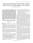
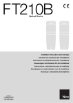
2.1 CAN Bridge
The Controller Area Network is widely used in the automotive industry today, and
its popularity is growing. In a network with separate CAN-busses, a bridge
between them would be desirable.
node
CAN bus
CAN bus
Bluetooth
node
node
node
Bridge
Figure 2.1. CAN bridge
Using Bluetooth for this application has its drawbacks. CAN is not suited for
packet radio transmission, one of the reasons for this being that CAN relies on
simultaneous transmission and reception of bits to achieve arbitration. This
demands that the nodes are synchronised to each other within a fraction of a bit
time. Also, a node on the bus must acknowledge that it has received a package
correctly within a very short time, typically from 2µs and up depending on the bit
rate used. This is simply impossible to achieve using Bluetooth as a transfer
medium. In non-realtime applications such as automotive diagnostics this is not a
problem, and guaranteeing that messages reach their destination, preferably within
a certain time, is sufficient. Unfortunately some of the built-in error handling
features of the CAN protocol will be lost or degraded.
The original project idea was to design and implement a universal converter that
with the Bluetooth technology connected to an arbitrary communication network,
could communicate wirelessly with a remote unit. In this thesis project the
possibility to bridge data is investigated for networks, in a point-to-point
connection with the same network protocol on each end of the connection.
As for any great product there is a need of a name. The project work name and
consequently the product name, has after consideration been settled to: Bluebus.
2.2 Problem and Objective
As the Thesis description evolved, the project was aimed for a specific industry,
the automotive industry, and initially for the heavy vehicle industry. The
advantage of aiming for a specific market is to get a fast response on interest and
9
Bluebus – Protocol Conversion for Wireless Data Exchange
feedback on customer needs. After contact with Volvo and a Tritech consultant
working for the Swedish company Autodiagnos, the decision was made to
investigate the possibilities to bridge the Controller Area Network (CAN), KWP2000 and RS232, which are all widely used in the vehicle industry today. The
standard J1587 was also mentioned and should be considered for future
expansions.
To limit the scope of the thesis work, a software implementation will only cover a
wireless serial interface with RS232. However, considerations are made to allow
future expansion of software to cover protocols mentioned above.
The objective of the project was to supply the customer with a prototype able to
connect and sustain a wireless serial connection. The hardware could consist of
development board circuitry, but schematics for the first compact version should
be submitted. In addition, thought should be given on in what context this kind of
product could appear.
2.3 Method of Attack
The Bluetooth technology was to be used as medium for the wireless link. This
was stated by the employer and is a core requirement for this project. The
Bluetooth technology and protocol was studied extensively and is described in
chapter four. Different communication networks used in the vehicle industry have
been overviewed. In this thesis the CAN, KWP-2000 and RS232 protocols are
covered in chapters five, six and seven. In these chapters an understanding of how
the protocols work is governed. The possibilities, requirements and limitations for
bridging these protocols are extracted and discussed. Moreover, a study had to be
conducted to select appropriate hardware. Among other things a Bluetooth module
and microcontroller had to be chosen, where the microcontroller handles control
and data conversion. The hardware study is presented in chapter nine. For the
software implementation the possibility of using an RTOS is investigated in
chapter eight. The architecture and operation of the software for packet conversion
and Bluetooth control is presented in chapter ten.
10
Bluebus – Protocol Conversion for Wireless Data Exchange
3 Product Idea
The vision is to design a small device, cheap and small enough to be fitted in a
vehicle or virtually any industrial product, allowing a wireless link for short-range
data communication. The device would supply a logically transparent connection
between two separate networks of the same type making them appear as one. In a
future perspective the device may even be able to bridge information between two
or more entirely different communication networks. In this scenario Bluebus
would have the characteristics of a gateway. As described by Jordan and
Churchill, (1990) the function of a gateway is to allow two or more dissimilar
networks to communicate as a single logical entity. Dissimilar means that the
transport protocols and the underlying physical networks are different. According
to Ewert (1999) a gateway is essentially a bridge. The difference is that a bridge
operates in the data link layer (layer 2) in the OSI model (Ewert 1999, page 110),
were as a gateway operates in layers 4 to 7. Bluebus may operate, though most
often in the data link layer, in any layer. No matter in which layer it does operate,
Bluebus is considered by the authors to bridge information and the term bridge
will be used in this thesis report.
3.1 Specification
3.1.1 Hardware
The hardware shall…
= have a Bluetooth interface.
= have an RS232 physical interface.
= be designed so that it is easily expandable. It shall be possible to add more
physical interfaces to the hardware if necessary.
= be optimised for low price and small size.
The hardware should…
= have CAN, J1708, and K-Line physical interfaces.
= have low power consumption.
3.1.2 Software
The software shall…
= be able to set up and sustain a connection with one remote Bluebus unit.
= be able to wirelessly send and receive serial data to/from a remote device.
= be designed so that more protocols can be added.
= not affect other connected nodes in a negative way. It shall not disturb
communications between other nodes or by itself initiate communication with
a node.
11
Bluebus – Protocol Conversion for Wireless Data Exchange
The software should…
= transfer CAN messages between two fieldbusses via the Bluetooth interface.
In the future, transferring messages between three or more busses is desirable.
= also be able to transfer the J1587 and KWP-2000 protocols.
= configure itself as much as possible. It should be able to determine which
physical bus/busses are in use at the moment.
= be “self-learning”. In the case of a CAN bridge, some information about the
connected nodes will be necessary. The system should collect as much of this
information as possible by itself. Self-learning in this context means that the
unit would be able to filter messages that is not intended to be transmitted
over the air.
3.2 Scenarios
In order to avoid or at least minimize built-in limitations when designing the
product it is important to think through the possible scenarios the product may be
involved in. A bunch of implementations could be thought of for this kind of
product. Here, four of the most interesting and likely scenarios for Bluebus are
presented.
3.2.1 Raw Data Exchange
Imagine two mobile units within relatively short range (10-100 m) from each
other. In each of these units there is a network, for instance a Controller Area
Network. There are possibly a number of nodes in each, exchanging data over the
internal network. Now, if information were to be exchanged between the units,
how would this be realized? The simplest solution would be to hardwire them to
each other with a cable. Thus, the two essentially becomes one network, but the
mobility is lost. The two units would have to follow each other around, so that the
cable between them is not broken. In this scenario two Bluebus units could be
connected, one on each mobile unit. The information would be bridged between
them and mobility and flexibility would be saved.
Along the same lines, Volvo has expressed interest in using Bluebus for an even
simpler matter (initially). Volvo would like to use Bluebus as a wireless serial
link. Instead of having a physical RS-232 line for raw data exchange, Bluebus
could accomplish the same thing but over the air.
3.2.2 Automotive Diagnostics
In most of today’s vehicles, different kinds of communication networks are
incorporated. Such a network could be an onboard diagnostics bus, which is used
to obtain vehicle status information. The information is transmitted by a physical
connection, with a cable, between the vehicle and the receiving diagnostic unit. It
would be desirable to break this connection, and instead use wireless
communication. This way the diagnosis could be made both easier and more
flexible. An interesting application could be, for example, if a car or truck broke
12
Bluebus – Protocol Conversion for Wireless Data Exchange
down, the driver could connect his cellular phone to the diagnostic system and
send information to a service station. Right away, the driver could get information
about if there is anything he can do himself to fix the problem, or he could find
out where the closest repair shop is located. If a service truck has to be sent out,
they would know what tools and spare parts to bring. In this scenario, our product
would be fitted into the vehicle, and in modified form in a mobile phone or in a
diagnostic unit.
Work developing a diagnostics application has already been initiated at Tritech
Mekatronik AB, as a thesis project. In this scenario a Bluebus unit would be
connected as a node on a diagnostic bus and another, possibly, in a PC (diagnostic
unit).
3.2.3 Bluebus in Line Production
Cars and trucks contain software to a large extent, which is downloaded at the end
of the production line. A cable is connected for download. A Bluetooth
application would be ideal. This idea is shared with (Lars-Berno Fredriksson) who
describes how this could be implemented in a car production line.
“When car on line gets connected to the Bluetooth base station, it uploads it serial
number. The production computer then downloads the software for this very car
via the fieldbus to the basestation, who in turn transmit to the car…”
(Fredriksson, 2000).
3.2.4 Ethernet Implementation
Imagine connecting an Ethernet circuit to the product, opening the opportunity to
access a network via Internet. In this scenario an OS would have to be considered,
preferably supplying a software stack for TCP/IP.
3.3 Proposed Solution
3.3.1 Method
The general idea is to design a simple universal protocol common for
communication between all networks supported by the system. All information
exchanged between Bluebus modules should be packaged in a standard Bluebus
packet frame. In this way, Bluebus becomes independent of which protocol is
being used by the network it is connected to, i.e. Bluebus would not care which
protocol a specific network is using. All communication could be conducted by
means of the Bluebus packet (specified in section 3.3.4). In context form the
situation is sketched in figure 3.1 for CAN. The situation would be the same for
any network protocol.
13
Bluebus – Protocol Conversion for Wireless Data Exchange
CAN message A in
CAN message A out
Bluebus
Bluebus
CAN message B in
CAN message B out
Bridge
Figure 3.1. Bluebus context diagram
Alternatively, messages from different protocols could be individually
programmed for in Bluebus. The protocol message would be sent to the Bluetooth
module (when using the Bluetooth unit for means of transportation) and then
packaged into a Bluetooth packet. This means that the Bluetooth unit needs
knowledge about the protocol structures for each protocol supported by the
system.
The advantage of using a standard frame is the flexibility. Additional networks, or
rather protocol standards, could easily be added to the Bluebus system. A newly
added protocol only needs software for conversion to the Bluebus format, and of
course appropriate hardware. This modularized thinking is also applied to means
of transportation. As mentioned earlier, network information should not solely be
communicated over Bluetooth, adding other means of transport should also be
possible. By adding destination information, i.e. for example in figure 3.2 the
destination information would determine whether the packet is transported via
Bluetooth or the Serial box in the figure. The destination information would also
determine which Bluebus unit may receive the transmitted packet. Moreover,
these two boxes would only have to be able to transmit Bluebus packets. On the
other hand, if each protocol message were to be transmitted in their original
format, the software would become very large and inflexible, supporting all these
separate protocols. Essentially, the entire program in Bluebus would have to be reprogrammed in order to support a new protocol. To gain flexibility and to assure
ease of expansion, the first alternative using a standard Bluebus packet frame
seems to be the most appropriate solution.
A third appealing solution would be to transmit data bit-by-bit over a radio
interface. For a CAN implementation this solution would have the advantage of
making it possible for message acknowledgement as described in the CAN
specification. The Bluetooth radio could theoretically be used with gross rate of 1
Mbit/s. However, bit-by-bit transmission is not supported by the Bluetooth
standard. Therefore, this method cannot be used.
14
Bluebus – Protocol Conversion for Wireless Data Exchange
3.3.2 Universal Packet Example
Suppose a CAN message was to be communicated from one network to another.
In this scenario, Bluebus would be connected as a node on each Controller Area
Network. When Bluebus retrieves the message, relevant information is extracted
and packaged into the Bluebus packet frame. The protocol includes information
regarding its destination, or means of transportation. In this case, the message is to
be transmitted over Bluetooth (It should be possible to transmit the message by
other means, such as over a serial interface). In the Bluetooth Module, the Bluebus
message is in itself also packaged in a standard Bluetooth packet and transmitted
over the air. On the other end, the Bluetooth module of the receiving Bluebus unit
receives the message. The message is unpacked and consequently in Bluebus
format again. The message is passed along to the application, were it is
interpreted. It becomes apparent that the received message was a CAN message.
The content is extracted and a CAN message is formed and transmitted on the
local Controller Area Network.
Bluebus
Packets
Bluebus
Packets
CAN
KWP-2000
e.g. Serial
Switch
Process
RS-232
Network
Connections
Bluetooth
Bluebus
Means of
Transportation
Figure 3.2. Bluebus concept idea
The switch process is basically an array with destination information, steering
Bluebus packets along the right track, i.e. it makes sure the packets are transmitted
with the desirable means of transportation (in this case over Bluetooth or the serial
interface). At this point, in the implementation part of the thesis work, Bluetooth
alone is used for means of transportation.
3.3.3 Additional Aspects
Additional aspects are configuration capabilities, reliability and filtering.
Depending on connection the demand for flawless versus fast transmission may
vary. For flawless connections, Bluebus should be able to re-transmit corrupt
messages. Bluebus should also be configurable for faster transmission with high
data rate, if a connection is relatively error free and high data rate is required. The
question whether to use an RTOS should also be raised and will be discussed in
chapter 8. Do tasks need to be scheduled? Can we get extra functionality for free,
using an RTOS?
15
Bluebus – Protocol Conversion for Wireless Data Exchange
Bluebus could be programmed for raw data exchange and take no consideration to
if a message is intended for the remote network, or if it is local message only. A
filtering mechanism should be considered so that only relevant information is
passed along to a remote destination. Filtering would increase performance and
efficiency since time is not wasted on unnecessary transmissions.
3.3.4 Proposed Packet Frame
The Bluebus packet frame could consist of Source, Target, Data length, Data and
Checksum. The Source field would provide a receiver with information what
Bluebus device sent a specific message. If there are several Bluebus units active,
the source information would allow the receiver to respond to a specific Bluebus
device.
The second field, Target, would provide destination information, i.e. targeted
Bluebus unit. This segment could possibly include what type of message is being
transmitted: CAN, KWP-2000, and J1587 etc. A question is if protocol type
should be included in the Bluebus frame or if that information should be a
configuration aspect?
The remaining fields are essentially mandatory. A data length field is needed to be
able to interoperate the data field, which is of variable length. The data field
includes the actual message being transmitted, i.e. appropriate parts of for
example a CAN, KWP-2000 or J1587 message. To conclude the frame a
checksum may be added to provide means for error checking. The maximum
overall size of the packet is 64K, which is the maximum allowed L2CAP payload.
The layout is sketched in figure 3.2.
Source
Target
Length
Data
Checksum
Figure 3.3. Bluebus packet frame
Segments could be included or excluded and this proposal should be seen as
foundation on which further work is based.
16
Bluebus – Protocol Conversion for Wireless Data Exchange
3.4 Test Specification
For initial testing and verification of product functionality, the converter will go
through the test procedures described in the subsections below. As a first step for
the thesis implementation wireless transmission of serial data will be tested.
Moreover, a proposal for CAN implementation tests is presented.
Figure 3.4. Ericsson’s Graphical User Interface
3.4.1 Bluebus to PC
Included in the Bluetooth development kit is a graphical user interface (GUI)
allowing the user to send HCI commands directly via the PC’s serial port to the
Bluetooth device. The program also displays received data and informs the user
when connection or disconnection occurs. Chapter 8 will cover the choice of
Bluetooth development tool. The GUI is a very useful tool to confirm a
connection, i.e. that Bluebus software is able to perform a connection. Once the
connection is up data may be sent from Bluebus. If data is sent successfully the
GUI will display the received data on the PC screen. This setup can also be used
to perform endurance tests, i.e. test if a connection can be sustained when data is
sent over a longer period of time.
17
Bluebus – Protocol Conversion for Wireless Data Exchange
3.4.2 HyperTerminal Test
The HyperTerminal program is a PC program that is included on most PCs. The
terminal can be used to send serial data on a PC’s COM port. Typically, a serial
cable is connected to another computer in the room. Data, for instance keyboard
input, can be sent to the other computer showing up on the HyperTerminal
window. Two Bluebus units replace this physical cable. The data exchange could
then be tested wirelessly. The HyperTerminal can also send complete files and this
would be the ultimate test for Bluebus.
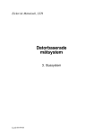
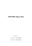
3.4.3 PC/CANAlyzer Test
The GUI allows the user to send HCI commands directly, via the PC’s serial port,
to the Bluetooth device. One can simulate a CAN message by sending the contents
of it in a Bluetooth packet from the GUI command line. The message is sent over
the air and received by the device on the other end of the connection. Inside
Bluebus the received data packet is unpacked. The CAN content is extracted and
re-assembled in CAN message format and then transmitted on the local CAN bus.
Hence, a CAN message from one network has been transmitted to another.
In order to analyze the message and verify its content, a CAN analyser, called
CANAlyzer may be used. The CAN analyser is connected directly on the outgoing
CAN port of Bluebus listening to all outgoing traffic. The CANAlyzer consist of a
CAN-PC-card and an application program. The application passively retains
messages and displays their contents on the screen. The situation is depicted in
figure 3.5.
PC with Bluetooth GUI
CAN message
from GUI
PC with CANAlyzer
RS-232
CAN message
Bluebus
Bluetooth Module
Figure 3.5. PC/ CANAlyzer test setup
18
Bluebus – Protocol Conversion for Wireless Data Exchange
3.4.4 LP transducer/ PC Test
A device, developed by Tritech, called LP transducer with CAN bus interface
(LP), may be used to send CAN messages (represents a CAN network). The LP is
a depth-sensing device developed for Atlas Copco’s drill rigs. The depth is
determined by measuring an electrical field, which is dependent on the position of
a magnetic ring on a steel rod. The value is transmitted on the bus and a host node
with a graphical interface displays the current depth, among several other things.
Additionally, our device could be connected as a node, transmitting the “depth”
wirelessly to a remote unit. The receiving unit may, as a first step, be the GUI
included in the Bluetooth starter kit, displaying the contents of received messages.
As a second step, there would be one Bluebus on each end. The receiving Bluebus
once again packs the user data into a CAN message frame and transmits it on the
local CAN network. Again, the CANAlyzer may be used to verify functionality.
19
Bluebus – Protocol Conversion for Wireless Data Exchange
4 Bluetooth
Bluetooth is the name of a new standard for short- range radio communication.
Mobile phone and computer manufacturers developed the technology. Companies
interested in developing their own Bluetooth application are members of the
Bluetooth Special Interest Group (SIG). The group include founding members
Ericsson, Nokia, IBM, Intel and Toshiba. Since its formation in May 1998, close
to 1800 companies (May 2000) have joined the Bluetooth SIG. Members get free
access to the technology, which in some aspects is protected by patent. As a
member, the company commits to not block or limit the Bluetooth technology.
The company is still permitted to develop and patent applications, of which
Bluetooth is a part. Originally, the objective was to form a standard for shortrange radio communication, to provide an easier connection between mobile
phones and mobile computers. Nevertheless, a wide range of companies and
industries has embraced the technology. Bluetooth will cut the wire or cable
connection between different devices such as mobile phones, headsets, fax
machines, printers, mobile computers, or to almost any digital peripheral device.
Only the imagination sets the limit.
The Bluetooth unit is a small, ready to mount, circuit for a wide range of products.
The connection is achieved by radio with a carrier frequency of 2.4-2.5 GHz. This
frequency band is globally designated for similar purposes. A binary FM
modulation is used, which minimizes transceiver complexity. The gross data rate
is 1 Mb/s. The standard uses frequency hopping, which means that the sending
unit sends one data packet, changes frequency, sends a new packet, and changes
frequency again. The procedure is then repeated over and over. The advantage of
this technique will be discussed in a subsequent section.
The following sections in this chapter will cover how data information is
communicated between Bluetooth units. Voice transmission is beyond the scope
of this paper and will not be described in any detail. In addition, essential Packet
structures and protocol architecture will be discussed.
4.1 Network Topology
A Bluetooth unit can establish a point-to –point connection, or a point-tomultipoint connection. In the later case, several Bluetooth units share the same
channel (see section 4.2). Two or more units sharing the same channel form a
piconet. In a piconet, one unit acts as master and the others as slaves. Up to seven
slaves can be active in one piconet. However, more slaves can be locked and
synchronized to the master, but they have to be inactive, in park mode. The master
for both active and parked slaves solely controls the access to the channel.
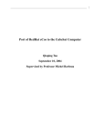
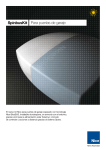
When different piconets are connected, a scatternet is formed. The options are
shown in figure 4.1 below. Slaves can participate in different piconets and a
master in one piconet can be a slave in another net. The piconets are not time-or
frequency synchronized, and each piconet has its own hopping channel.
20
Bluebus – Protocol Conversion for Wireless Data Exchange
Figure 4.1. Bluetooth connections.
(a) Point-to-point piconet, (b) multislave operation, (c) Scatternet
A device participating in several piconets apply time multiplexing, where it
reserves time for each net. As a result of this, its performance will be slightly
decreased. For further information, please refer to (SIG 1999, section 10.9, pp.
122-125).
4.2 The Baseband
The Baseband circuit is the digital part of the Bluetooth module, controlling radio,
Bluetooth clock, radio frequency, frequency hopping, and the hop sequence.
Information is exchanged using packets. Each packet is transmitted at a different
hop frequency in a Bluetooth channel. The channel is defined by a unique
sequence of frequency changes, hopping at a maximum rate of 1600 hops/sec.
The technique used is called Frequency Hop Spread Spectrum (FHSS). The
spectrum allows up to 79 channels with a channel bandwidth of 1 MHz. The
sequence is determined by the Bluetooth device address of the master. All
Bluetooth units participating in a piconet are synchronized to this channel. The
channel is divided into time slots, where each slot corresponds to an RF hop
frequency. The frequency stays the same for one slot time, which is 625 ←s long,
provided that the packet does not occupy more than one slot. Packets covering
one, three, or five time slots are defined. In each case the frequency remains fixed
for the duration of the packet.
The advantages of using frequency hopping are that several transmitters can send
at the same time and a connection is tolerable to interference. The data throughput
might be degraded, but the connection will, with high certainty, not collapse. The
challenge with Spread spectrum is to find the hop sequence, which most certainly
is a reason for why the military has used this technique for safe communication.
The Bluetooth standard supports one asynchronous channel, up to three
simultaneous synchronous channels, or a channel that supports an asynchronous
and a synchronous channel at the same time. Each synchronous channel can
transmit 64 kb/s full duplex, which mainly is used for voice transmission. Each
21
Bluebus – Protocol Conversion for Wireless Data Exchange
asynchronous channel can transmit up to 723.2 kb/s in one direction and up to
57.6 kb/s in the return direction. In the case of symmetric transmission the data
rate is up to 433.9 kb/s. In order to limit the impact of noise on the Bluetooth
radio, forward error correction (FEC) can be used. This reduces the number of
retransmissions, but also decreases the data rate. For detailed information about
the Baseband and the Bluetooth channel, see (SIG 1999, part B).
4.3 Network Configurations
There are two types of links defined in the Bluetooth specification.
= ACL-Asynchronous Connectionless Link
= SCO-Synchronous Connection Oriented Link
4.3.1 ACL Link
In an ACL link most ACL packet types are retransmitted, if not transmitted or
received correctly. Therefore, this is considered to be a reliable link. The ACL link
provides a packet switched connection with one or all slaves in the piconet. The
master transmits packets, on a per slot basis, at “even” time slots. Independent of
the packet length, one, three, or five slots, a slave is only allowed to respond in the
next “odd” time slot, provided that it was addressed in the preceding master-toslave time slot. An ACL packet with the Active member Address (AD_ADDR) 0
is interpreted as a broadcast message and is received by all connected slaves. In
case of a broadcast message, no slave is allowed to return a packet (an exception
is found in the access window for access requests in Park mode, see SIG 1999,
section 10.8.4, pp. 115). As implied in part of the name, connectionless, no
transmission shall take place if there is no data to send.
The associated packets are listed in table 4.1
2/3
Symmetric
Max. Rate
(kb/s)
108.8
Asymmetric Max. Data Rate Overhead2
(kb/s)
In (%)
Forward
Reverse
108.8
108.8
62.8
27
No
172.8
172.8
1727.8
41.0
3
121
2/3
258.1
387.2
54.4
40.1
DH3
3
183
No
390.4
585.6
86.4
9.4
DM5
5
224
2/3
286.7
477.8
36.3
37.5
DH5
5
339
No
433.9
723.2
57.6
5.4
AUX1
1
29
No
185.6
185.6
185.6
36.6
Packet
Type
Number
of Slots
1
User
Payload
(bytes)
17
DM1
DH1
1
DM3
FEC1
Table 4.1. ACL data packets
1
2
FEC: Forward Error Correction
Number of overhead bits by the total number of bits in respective packet type
22
Bluebus – Protocol Conversion for Wireless Data Exchange
The ACL data packets use CRC (Cyclic Redundancy Check), with exception for
the AUX 1 packet, to check for error. Hence, in case of an error a packet is
retransmitted. Except for the AUX 1 packet, there are two types of packets: The
DM (Data Medium Rate) and DH packet (Data High Rate). The difference is that
DM packets use FEC (Forward Error Correction), for which the data rate is
slightly reduced. One the other hand the FEC allows the payload to be
reconstructed if corrupted, for instance, by random noise. As indicated by the
packet name, a packet occupies one, three or five time slots. The slot length is 625
µs, and up to 366 µs is used for transmission. The remaining time is needed to
switch to the next frequency in the hop sequence. If both master and slave sends
packets covering a single time slot the time division scheme in figure 4.2 is
obtained.
TX slot
RX slot
366 µs
625 µs
1250 µs
Figure 4.2. Slot timing, using one slotted packets.
The example is seen in the eyes of the master and DM1 or DH1 packets are used
(AUX1 packets could also be used). In figure 4.3 an asymmetric situation is
shown.
TX slot1
TX slot 2
TX slot 3
RX slot
625 µs
2500 µs
Figure 4.3. Slot timing (master: 3 slots, slave: 1 slot)
In this case the master starts transmission on an even time slot using a DH3
packet, or a DM3 packet. The slave responds with a 1 slotted packet. The selection
of high-rate data or medium-rate data shall depend on the quality of the link.
When the quality is good, the FEC in the data payload can be omitted, resulting in
a DH packet. Otherwise, DM packets must be used.
From the examples the effective data rates in table 4.1 can be derived. Consider
the case when the master sends DH3 packets with up to 183 bytes every 2500 µs
and the slave responds with DH1 packets, with up to 27 bytes. The maximum
forward asymmetric data rate for DH3 packet is 183·8 bits/2500 µs= 585.6 kb/s
and in reverse with DH1 packets 27·8 bits/2500 µs = 86.4 kb/s. The remaining
fields are determined in the same manner. Detailed information about all data and
control packets can be found in (SIG 1999, section 4.4, pp.54-61).
23
Bluebus – Protocol Conversion for Wireless Data Exchange
4.3.2 SCO Link
The SCO link operates on reserved time slots. This provides a fast transmission of
packets with a guaranteed time interval, but is not considered a reliable link since
the SCO packets are never retransmitted. The SCO link is a symmetric, point-topoint connection between the master and a specific slave. This type of connection
is considered to be circuit-switched since it operates on reserved slots. The SCO
link typically supports time bound information like voice. As for the ACL link an
addressed slave may respond to the master in the next slave-to-master time slot.
Even if the SCO slave fails to decode the slave address in the packet header, it is
still allowed to return an SCO packet in the reserved SCO slot. The SCO link is
not used in this project and will not be further discussed. For additional
information on the SCO link, refer to (SIG 1999, section 3.2, pp.45, 46).
4.4 The Baseband Packet
This section describes in more detail the format of the baseband packet and is not
crucial to understand how Bluetooth operates. Therefore, the reader may skip to
the next section if not particularly interested in the baseband packet format.
All information is physically transported via the baseband, and the baseband
packet. The standard frame is shown in figure 4.4. The packet can consist of, the
access code only and is used in paging and inquiry procedures, access code and
header, or of access code, header and payload. The access code is used for
synchronization; DC offset compensation, and identification.
LSB
72
ACCESS
CODE
54
0-2745 bits
HEADER
MSB
PAYLOAD
Figure 4.4. Standard packet frame
Three different access codes are defined.
= Channel Access Code (CAC)
= Device Access Code (DAC)
= Inquiry Access Code (IAC)
The different codes are used depending on operation mode. The channel access
code defines the channel of a piconet, and is include in all packets sent by the
master. The code is derived from the lower address part of the master Bluetooth
address (BD_ADDR). The device access code is used during page, page scan and
page response substates. This code is derived from the unit’s BD_ADDR. Finally,
the IAC is used for inquiry operations. The code can be of two kinds: First, the
General Inquiry Access Code (GIAC), which is used to discover all Bluetooth
units within range. The second is the Dedicated Inquiry Access Code (DIAC),
which is used to discover a group of units sharing a common characteristic.
24
Bluebus – Protocol Conversion for Wireless Data Exchange
As indicated by the figure the length of the access code is 72 bits. However, if a
DAC or IAC is sent no header is present and the access code field can be reduced.
A part called the trailer (4 bits) of the field is excluded. In this scenario the length
of the access code is reduced to 68 bits. For further detail, refer to the Bluetooth
baseband specification (SIG 1999, part B).
The next part of the frame is the header field; see figure 4.5 showing its content
LSB
3
AM_ADDR
4
TYPE
1
1
FLOW
ARQN
1
8
SEQN
HEC
MSB
Figure 4.5. Header content (lengths in bits)
AM_ADDRActive member address, which is used to distinguish between
the members of a piconet. This address is included both in
master-to-slave and slave-to-master communication. For
broadcast messages this field is set to all zeros.
TYPE
There are sixteen packets defined. Firstly, the type determines if
a packet is sent on a SCO link or an ACL link. Secondly, it
determines how many slots the packet occupies. The sixteen
packets are divided into four segments. The first segment
contains four packets that are common for both ACL and SCO
packets. Segment two includes six packets, all occupying only
one time slot. Segment three and four are for packets occupying
three and five time slots, respectively.
FLOW
When the receiver buffer is full and not emptied a stop
indication is returned (FLOW=0) to stop the transmission
temporarily. Packets including only link information (ID, POLL
and NULL packets) or SCO packets may still be received
ARQN
SEQN
HEC
ARQN is an acknowledge indication used to inform the source
of a successful transfer of payload data. The success is checked
with a CRC code and the acknowledge is piggybacked in the
header of a return packet.
This is used to distinguish between retransmitted packets and
new packets. Each time a packet containing data with CRC, the
SEQN bit is inverted. If a retransmission is made due to a failing
ACK the destination receives the same packet twice. By
comparing the SEQN of consecutive packets, correctly received
retransmissions can be discarded.
8-bit header error check (see section 4.5 error correction).
25
Bluebus – Protocol Conversion for Wireless Data Exchange
The last field is the payload field, which can include ACL or SCO payload
information. Here, only the data field structure will be handled. The field consists
of three segments: a payload header, a payload body and a CRC code. See figure
4.6.
2
L_CH
1
5
FLOW
16
LENGT
PAYLOAD BODY
CRC
Header
Figure 4.6. Payload segment
L_CH
Logical Channel Field, see table 4.2
L_CH Code
Logical
Channel
00
NA
01
UA/UI
10
UA/UI
11
LM
Information
Undefined
Continuation fragment of an L2CAP
message
Start of an L2CAP message or no
fragmentation
LMP message
Table 4.2. Logical channel field
FLOW
LENGTH
Controls flow on the L2CAP level. The Link manager is
responsible for setting this bit. (FLOW=0; flow off)
Number of bytes in the payload body.
The information in this section is extracted from (SIG 1999, chapter 4, pp.47-66).
4.5 Error Correction
4.5.1 FEC Coding
The Data Medium rate ACL packets are protected by a 2/3 Forward Error
Correction code (FEC). The scheme is a (15,10) shortened Hamming code. The
generator polynomial used is g (D) = (D+1)(D4+D+1). Essentially a 15-bit code
word is used to represent 10 bits. The code is able to correct all single errors and
detect all double errors in each codeword. For a connection not producing many
errors the FEC only impose unnecessary overhead, reducing the data rate to 2/3.
The packet header is also protected. The header is always protected by 1/3 FEC
because it contains important link information and needs to be sustained. The code
is implemented by simply repeating each bit in the header three times.
26
Bluebus – Protocol Conversion for Wireless Data Exchange
4.5.2 ARQ (Automatic Repeat reQuest) Scheme
All the ACL data packets, except the AUX1 packet, include a 16-bit Cyclic
Redundancy Check (CRC) for the packet payload. The polynomial used to
generated the CRC is g (D) = D16+D12+D5+1. Furthermore, the packet header is
checked with an 8-bit checksum called Header Error Check (HEC). The HEC is
generated by the polynomial g (D) = D8+D7+D5+D2+D+1. For detailed
information on checksum generation, see (SIG 1999, Chapter 5, pp.66-76).
Upon reception of a packet these checksums are calculated and confirmed. If the
checksum for the payload fails the receiver requests a retransmission of the
packet. Bluetooth uses an unnumbered acknowledge scheme, where an ACK or a
NAK is returned in the packet header of the responding packet of the slave. The
response is transmitted on the next slave-to-master slot following the reception of
the packet from the master. The master will respond the next time it addresses the
slave, which may be after addressing several other slaves.
The ARQ scheme is only applicable to links using packets including CRC. The
data payload is retransmitted until a positive acknowledge is received or a time out
is exceeded. For some communication links only a limited delay is allowed and
new payload must be allowed. In case of timeout, the old packet is flushed and the
controller is forced to consider the next data instead. Details on the ARQ Scheme
may be found in (SIG 1999, Section 5.3, pp.68-77).
27
Bluebus – Protocol Conversion for Wireless Data Exchange
4.6 Error Checking
Packets are checked for errors or wrong delivery using the channel access code,
the HEC in the header, and the CRC in the payload. At packet reception the access
code is checked first. Since the 64-bit sync word in the access code is derived
from the 24-bit master LAP (Lower Address Part of Bluetooth Device Address),
this checks if the LAP is correct, and prevents the receiver to accepting packet of
another piconet. The HEC and CRC are used to check both for errors and wrong
address. For detailed information of how the HEC and CRC is generated please
refer to (SIG 1999, section 5.4, pp.73).
4.7 The Bluetooth Connection
The steps for connection between units can be summarized like:
= Initialisation of Bluetooth units
= Inquiry Phase- discovering units within radio range
= Connection set-up
o Includes Page phase
= Data and/or voice transfer
= Disconnection
4.7.1 The Inquiry Procedure
The first step after initialisation, to create a connection, is the inquiry phase.
A unit waiting to be discovered periodically enters the Inquiry scan state, listening
for an inquiry messages from the master. The unit scans over a sequence of 32 hop
frequencies and when it detects an IAC it can respond to the inquiring (master)
unit. As response the device sends a FHS packet containing its address and clock
value. The scanning unit can either be listening for general access codes (any unit)
or for dedicated inquiry access codes (a specific type of unit).
The master sends ID packets continuously over a range of hop frequencies and
scans for response after each transmission. The inquiring unit does not
acknowledge any inquiry responses it receives. The Inquiry continues until it is
terminated by the Link Manager (enough responses received) or a timeout occurs.
4.7.2 The Page Procedure
As explained in the Bluetooth specification, paging is used to set up a connection
with a known unit. To connect to an unknown unit, the slave must respond to the
inquiry message as explained above. Once the unit is known a connection can be
established by paging the unit. The page procedure is very similar to the inquiry
procedure.
During this phase the master estimate the slave clock offset, and uses this to start
the page on frequencies close to this estimate by sending ID packets containing the
slave’s address. To ensure connection the master uses a “Train” that is 10ms long
28
Bluebus – Protocol Conversion for Wireless Data Exchange
consisting of 16 time slots at different frequencies. The train include the estimate;
eight preceding frequencies and seven frequencies post the estimate. If this would
not be enough a second train of additional 16 frequencies will be used. Eight
frequencies placed on each side of the first train, broadening the frequency range
even more.
The slave is in Page Scan state and listens for its device access code i.e. a page
message from the master. The slave stays fixed at one hop frequency, at least 18
consecutive slots, while looking for its Device Access Code (DAC). The scan
frequency is derived from the unit’s address (BD_ADDR) and its native clock.
Every 1.28 s the scanning frequency is changed. Once the slave recognizes its ID
packet it responds. Upon response, the master sends a Frequency Hop Sequence
(FHS) packet supplying the slave with the master’s clock offset and Bluetooth
address. Furthermore, the master assigns an active member address to the slave
that is used for the remainder of the connection. The slave can now start hopping
with the master. For more information about access procedures refer to (SIG 1999,
section 10.6, pp.99-107). Figure 4.7 below displays the connecting states
discussed above and other possible states of a Bluetooth unit.
Figure 4.7. Bluetooth device states
4.7.3 Active States
In the Active state mode, a Bluetooth device actively participates on the channel.
The master schedules all transmissions to the slaves. Active slaves listen in the
master-to-slave slots for packets. If not addressed at the time, the slave may sleep
until the master transmits again. However, periodic transmission is needed to keep
the slave synchronized to the channel. This is easily obtained since only the channel
access code is needed for synchronization, which is included in all messages sent by
the master.
29
Bluebus – Protocol Conversion for Wireless Data Exchange
4.7.4 Park Mode
If a slave does not need to participate in a channel, at the time, it can be placed in
park mode. The slave gives up its Active Member Address, but still stays
synchronized to the master. The slave can wake up again at a master beacon
instant. The beacon is repeated periodically and the master can activate the slave,
transmit broadcast information, or change park mode parameters at the beacon
instant.
4.7.5 Hold Mode
An ACL link between two Bluetooth devices can be placed in hold mode for a
specific hold time. The master will send no ACL packets during this time. This
mode can be entered if no data needs to be transmitted for a long time. The
transceiver can then be turned off to save power.
4.7.6 Sniff Mode
When a link is in sniff mode the master can only start a transmission in a sniff
slot. The interval of these slots is a result of a negotiation between the master and
the slave. Both units, must agree to enter sniff mode, and can request to enter sniff
mode.
30
Bluebus – Protocol Conversion for Wireless Data Exchange
4.8 Bluetooth Software Stack
The essential Bluetooth software stack is shown in Figure 4.8. The Bluetooth host
denotes the user, e.g. a PC or a processor that uses the Bluetooth module to
communicate with a remote system. The bottom layer of the Bluetooth module
provides means for the physical transmission of packets as described in section
4.3.
Higher Layers
L2CAP
HCI
Bluetooth Host
Bluetooth
Complete
Module
Transport
Layer
HCI
Link Manager
Baseband
Radio
Figure 4.8. Bluetooth software stack
The Link Manager (LM) is responsible for link set-up, security and control. LM
messages have higher priority than user data, and are transferred in the payload
instead of data. The message is distinguished by a reserved value in the payload
header. Messages are filtered out and interpreted by the Link Manager on the
receiving end and is not propagated to higher layers. How the Link Manager
actually works inside is not essential and is left for the reader to learn about.
Information can be found in (SIG 1999, part C, pp.191-239).
The Host Controller Interface (HCI) is the programming interface to access the
Bluetooth device and will be handled in section 4.8.1. The Host controller
represents the controller inside the Bluetooth module that communicates with the
host. Via the HCI the host can set up and maintain a link with a remote system
over Bluetooth.
The Logical Link Control and Adaptation Layer Protocol (L2CAP) is layered in
the data link layer and is only used for ACL links, i.e. there is no support for SCO
links. The purpose of L2CAP is protocol multiplexing, enabling usage of higher
layer protocols such as RFCOMM, HID and TCP/IP. Essentially, L2CAP hide the
data link packet lengths for higher layer protocols. Moreover, it segments higher
layer packets (up to 64k bytes) into appropriate data link packets and reassembles
them again on the receiving end. Channels as described, recognize connections
between devices. The end points of an L2CAP channel have its own channel
identifier (CID), which provide the end points with a local name. Each channel
can only use one higher-level protocol and is recognized by L2CAP. In other
31
Bluebus – Protocol Conversion for Wireless Data Exchange
words multiple channels can use the same protocol, but a channel cannot be used
by multiple protocols.
Only a portion of L2CAP will be used in this project. The reason is that the
Ericsson Bluetooth module requires the use of the L2CAP packet format when
sending data. Except from this all control of the Bluetooth module is handled with
HCI commands. This deviation from the Bluetooth specification is further
discussed in section 9.2. For details on L2CAP refer to (SIG 1999, part D, pp.
245-313).
4.8.1 Host Controller Interface (HCI)
The Host Controller Interface, part of the Bluetooth firmware, provide a format to
reach the Bluetooth hardware capabilities. It is a command interface to the
baseband, the Link Manager, and to various host controller registers. In this
project all control of the Bluetooth device is done using HCI commands. The
functionality could be fully implemented in the host software, but then losing the
advantages of a flexible and structured layered software.
The HCI is divided into Command and Event. Typically, the host sends a
command to the host controller and when the controller has carried out its task, it
responds with a command complete event. The HCI driver converts commands
into HCI packets and the packets are transported by underlying software to the
Bluetooth module. The use of HCI packets makes the layer independent of means
of physical transportation. In the Bluetooth specification USB, UART and RS-232
are mentioned for physical transportation. Once in the Bluetooth module the
physical bus driver converts the data back into HCI packets. The packets are
transported to the HCI firmware, where the commands are interpreted and actions
are taken accordingly.
HCI commands may take different amounts of time to carry out. For this reason,
the host controller responds with the result of the command in form of an event.
To detect errors on the physical link a time out shall be defined. The Host
Controller Interface Functional Specification recommends a default time out of
one second; from the time a command is received to the moment a response is
sent.
4.8.2 HCI Packets
The Host can send HCI commands, ACL data and SCO data to the Host
Controller. In the opposite direction the Host controller can send HCI events, ACL
data and SCO data to the Host. All parameter values, unless noted, are sent in
"Little Endian" format, i.e. the least significant byte is transmitted first. The
parameters in non-arrayed and all elements in an arrayed parameter have fixed
size. Parameters are noted: parameter A[i]. If multiple arrays are used the order of
the parameters are as follows: Parameter A[0], Parameter B[0], Parameter A[1],
Parameter B[1], … Parameters A[n], Parameters B[n].
32
Bluebus – Protocol Conversion for Wireless Data Exchange
4.8.3 HCI Command Packet
The format of the HCI Command packet is sketched in figure 4.9. Each command
contains an Opcode (2 bytes), uniquely identifying different commands. The
OpCode consist of two components. First, the OpCode Group Field (OGF)
identifying a specific cluster of commands, such as Link Control Commands, Link
Policy Commands, Host Controller & Baseband Commands, etc. Secondly, the
OpCode Command Field (OCF) defines the commands in a specific cluster. The
OGF occupies the upper six bits and the OCF the remaining lower ten bits of the
OpCode.
OpCode
OCF
Parameter Total
Length
OGF
Parameter 1
Parameter 0
Parameter …
Parameter N-1
Parameter N
Figure 4.9. HCI command packet.
The Parameter Total Length (1 byte) field defines the number of bytes in the
following parameters, and not the number of parameters. The Host Controller
must be able to receive up 255 bytes of parameters plus the three-byte header.
In most cases, when a command has been executed, the Host Controller returns a
Command Complete Event to the Host. However, some commands are not
verified with a Complete Event. Instead a Command Status event is sent back
when the command execution has started. In case of an error the cause of the error
will be included in the Command Status event. Later on when the command is
carried out, a command complete event may be sent. Each command is specified
in (SIG 1999, parts 4.5-4.10, pp. 540-702) with command parameters, return
parameters and associated events generated for that command.
33
Bluebus – Protocol Conversion for Wireless Data Exchange
4.8.3.1 An Example
As an example one command, the HCI_Inquiry command, can be defined in short
(extracted from the Host Controller Interface Functional Specification):
Description:
The HCI_Inquiry command causes a device to enter inquiry mode to discover
units within range. The command belongs to a group named Link control
Commands with the OGF 0x01. The OpCode Command Field for this command
is 0x0001.
Command parameters:
= LAP (3 bytes): The value from which the inquiry access code will be
generated.
= Inquiry_Length (1 byte): Maximum amount of time before the inquiry
procedure is stopped. Range: N = 0x01-0x30. Time = N*1.28 seconds.
= Num_Responses (1 byte): Maximum number of responses accepted before
the inquiry process is halted. Range: 0x01-0xFF.
Return parameters:
= None
Events generated:
= Command Status Event, when inquiry is started.
= Inquiry Result Event, when a device responds.
= Inquiry Complete Event, when the inquiry procedure is finished in
compliance with the command parameters.
4.8.4 HCI Event Packet
The format of the HCI Event packet is shown in figure 4.10. Each Event is
distinguished with an Event Code (1 byte) in the first segment of the packet. The
number and kind of parameters are specific for the respective event. The possible
events are defined in (SIG 1999, chapter 5, pp. 703-744).
Event Code
Parameter Total
Lenght
Event Parameter 1
Event Parameter 0
Event
Parameter 2
Event Parameter N-1
Event
Parameter 3
Event Parameter N
Figure 4.10. HCI event packet
The Host must be able to accept HCI Event packets with up to 255 bytes of data
excluding the packet header.
34
Bluebus – Protocol Conversion for Wireless Data Exchange
4.8.5 The HCI ACL Data Packet
The HCI Data Packet is used to exchange data between the host and the host
controller and is sketched in figure 4.11 below. Here, only the ACL data packet
will be described. The SCO data packet is defined in (SIG 1999, section 4.4.3,
pp.538, 539).
Connection Handle
PB
Flag
BC
Flag
Data Total Length
Data
Figure 4.11. HCI ACL data packet
The Connection Handle, a 12-bit identifier for transmitting and receiving voice or
data, is used to identify a connection between two Bluetooth devices. An assigned
connection handle is used by the host Controller for the remainder of the present
connection. The Packet Boundary Flag (PB Flag, 2 bits) indicate weather or not
the packet contains a continuing fragment of a higher layer message or if it is the
first part of a higher layer packet (so far only a L2CAP message). The Broadcast
Flag (BC Flag, 2 bits) set to 00 indicate a point-to-point transmission, 01 means
the packet will be sent to all active slaves (Active Broadcast), 10 indicates that the
packet will be sent to all the slaves, including slaves in ‘Park’ mode (Piconet
Broadcast). The Data Total Length (2 bytes) gives the number of bytes in the Data
segment.
4.9 Data Transfer using L2CAP
A master can transfer information to a slave whenever it wishes to. However, if a
slave wishes to transfer data the master must have addressed it. If the master has
no data to send to the slave, it invokes a polling mechanism by sending Poll
Packets to the slave. This way the slave is given the opportunity to transfer data.
To explain the transfer procedure and how two devices interact, consider the
following example:
Host 1 (local) wants to transfer 26 bytes of information to host 2 (remote). A
connection is established and the packet type used for the session is the DM1
packet. The 26 bytes of data represent the L2CAP messages and do not fit into one
DM1 packet. Therefore the data is segmented and sent in two DM1 packets.
The situation is sketched in figure 4.12.
35
Bluebus – Protocol Conversion for Wireless Data Exchange
L2CAP
Lenght
CID
L2CAP Payload
Connection_handle PB-flag = 10
Lenght
HCI data payload
HCI
Connection_handle PB-flag = 01
Lenght
HCI data payload
Figure 4.12. segmentation of L2CAP packet.
The first HCI packet includes the L2CAP header, namely Length and CID (4
bytes) and 13 bytes of data in the HCI data payload. The Packet boundary flag
(PB-flag) is set to “first packet of higher layer message”. The second HCI packet
includes the remaining 13 bytes of data in the HCI data payload. This time the PBflag is set to “continuation of higher layer message”. On the receiving end the host
software will re-assemble the two packets in order to create the 26 bytes of
information packet originally sent.
4.10 Bluetooth Security
The Bluetooth standard provide two types of security measures, authentication and
encryption. Authentication is used to verify, before information is exchanged, that
a counter part really is the individual it claims to be, and not an intruder.
Encryption is the process where sent information is encoded in such way that only
the addressed device is able to decode it. Other units shall not be able to listen to
this private information. The system is not airtight and with high effort an intruder
could decode an encoded messages, and/or illegally pass the authentication. For
most applications the security is considered to be satisfactory. The security is
adjustable by a variable key used for encryption. The size of key may vary
between 1 and 16 octets. If further security is needed this shall be implemented at
the application layer. For the first connection between two devices, the security
procedure is depicted in figure 4.13.
Generate initialization key
PIN
Authentice
Generate link key
Exchange link key
Figure 4.13. Security, first connection
36
Generate encryption key
Bluebus – Protocol Conversion for Wireless Data Exchange
The PIN code can be a fixed number provided with the Bluetooth the user could
arbitrarily change unit, or it if a Man Machine Interface (MMI) is present. In the
later case the number is entered in both units and later matched. The security
procedure for following connections between the same units is depicted in figure
4.14.
Get current link key
Authenticate
Generate encryption key
Figure 4.14. Security procedure (following connections)
The link key is a 128-bit random number, which is shared between two or more
parties and is the base for all security transactions between these parties. The link
key is used in the Authentication routine. Furthermore, it is used as one of the
parameters when the encryption key is derived.
4.10.1 Authentication
The authentication is based on a challenge-response scheme. The unit requesting
another unit to prove himself is called the verifier and the requested unit, claimant.
For the authentication to succeed, the procedure requires that both units share the
same secret key. The verifier, e.g. unit A, sends a random number AU_RANDA to
the claimant, unit B. The situation is displayed in figure 4.15. Both units calculate
an authentication code, SRES, using the algorithm E1 with the inputs AURANDA, BD_ADDRB and Link key (128-bits). The verifier compares its result
with the claimant’s, and if they coincide, the authentication is a success.
Verifer (Unit A)
AU_RANDA
AU_RANDA
BD_ADDRB
Claimant (Unit B)
E1
AU_RANDA
E1
Link key
BD_ADDRB
Link key
SRES
SRES’
SRES
=
SRES(?)
Figure 4.15. Challenge-response
In some peer-to-peer communications, mutual authentication might be
appropriate. In this case, unit a first request unit B to authenticate as described
above, and then the procedure is reversed. Only, this time unit B sends the random
37
Bluebus – Protocol Conversion for Wireless Data Exchange
number, AU_RANDB, and BD_ADDRA is used to determine SRES. The order in
which to authenticate is decided by the link managers.
If an authentication fails, the time between attempts will be increased. For each
subsequent authentication failure with the same Bluetooth address, the waiting
interval is increased exponentially and decreased if new attempts do not fail. This
procedure prevents an intruder to repeat the authentication procedure with a large
number of different keys. For greater detail about Authentication, see (SIG 1999,
section 14.4, pp. 169-171).
4.10.2 Encryption
Protecting user data is done through encryption, where ciphering bits are bit-wise
modula-2 added to the data stream. The cipher is symmetric, meaning that the
deciphering is done exactly the same as encryption with the identical key. The
payload is ciphered, including the CRC bits, but not the forward error correction
code. Each packet payload is ciphered separately with the cipher key, K Cipher. The
cipher key is determined by the algorithm E0, using the master Bluetooth address,
26 bits of the master real-time clock and the encryption key, Kc, as inputs. The
effective cipher key length can be set to any multiple of eight between one and
sixteen (8-128 bits). The situation is sketched in figure 4.16.
Unit A (master)
EN RANDA
BD_ADDRA
ClockA
Unit B
BD_ADDRA
ClockA
E0
KC
E0
KC
Kcipher
Kcipher
DataA-B
Data
DataB-A
Figure 4.16. Encryption procedure
Before the master enters encryption mode, the master sends a 128 bit random
number, EN_RANDA, allowing the slave to determine Kc together with the current
link key and a 96-bit Cipher Offset number (COF). Since at least the clock value
changes for each transmission, the cipher key is continuously changed, making it
hard for an intruder to encode a message. The cipher algorithm is defined in (SIG
1999, section 14.3, pp.159-169).
38
Bluebus – Protocol Conversion for Wireless Data Exchange
4.11 Observations
The data throughput and error tolerance can be set using different packet types. If
a connection is relatively error free the DH packet should be used, providing the
highest data rate. Depending on the amount of data DH1, DH3, or DH5 may be
chosen. For instance a CAN message would fit into a DH1 packet, providing the
fastest possible transmission of that particular message. On the other hand
accumulated packets, if heavy traffic on the CAN network, could be bridged using
a DH3 or DH5 packet, providing a much higher data rate (see table 4.1, pp.14).
When a connection has to work in a noisy environment, the forward error
correction code (FEC) can be added, increasing error tolerance. Using FEC will
reduce the data rate, but effectively the throughput may be increased since the
FEC decreases the number of re-transmissions due to packet errors.
The Bit Error Rate (BER) is important to keep in mind while designing a
Bluetooth implementation. According to the specification the BER is set to 0.1%
at range limit. Consider the case when the longer packets are used. For instance
the DH3 and DH5 packets contain about 1500 and 2700 bits, respectively. With
BER at 0.1%, i.e. one out of a thousand bits are corrupt; the consequence will be
that these packets will essentially be retransmitted infinitely. The cure for this
problem is simply to send data in shorter packets.
39
Bluebus – Protocol Conversion for Wireless Data Exchange
5 The Controller Area Network
BOSCH developed the Controller Area Network (CAN) in the early eighties for
the car industry. CAN offer a high-level safety, reliable and robust data link, over
a two wire serial bus. The acceptance today is worldwide and CAN is used in a
wide range of products. Industrial examples are marine control and navigation
systems, agricultural machinery, medical systems and textile production
machinery. Two of the most important features of CAN are the automatic error
handling, done by hardware and the guaranteed latency for bus access, which
especially makes it very suitable for real-time applications.
CAN covers layers 1 and 2 in the ISO/OSI model and are described in the
international standard ISO 11519-2 for low speed applications and ISO 11898 for
high speed applications. Enhancements of the original specification are available
for the application layer such as CAN Kingdom, SDS, CANopen and DeviceNet.
The data link layer services are implemented in the Logical Link Control (LLC)
and Medium Access Control (MAC) sub-layers of the CAN controller. The LLC
handles acceptance filtering and services for data transfer and data requests.
Furthermore, it provides overload notification and recovery management. The
MAC is responsible for frame creation, error detection, error signalling, and
acknowledgement and controls the access to the bus. The physical layer provides
means for transmission of dominant and recessive bits, where the dominant bit
overwrites the recessive bit if transmitted at the same time.
5.1 Physical Layer
The CAN bus basically consist of two lines CAN_H and CAN_L with terminating
resistors in both ends as shown in figure 5.1.
Figure 5.1. Network setup
However, CAN do not require a specific medium. Optic fibre or even radio could
be used, but the most common is the use of twisted pair cables, as described in the
specification ISO/WD11898-2 (1999).
Whichever medium, the bit level is always interpreted by the differential between
CAN_H and CAN_L. The bus state can either be dominant (normally referred to
as a logical 0) or recessive (normally logical 1). See figure 5.2.
40
Bluebus – Protocol Conversion for Wireless Data Exchange
Figure 5.2. Nominal bus levels.
A recessive bit is detected when CAN_ H is less than 0.5 V higher than CAN_L.
If the CAN_H is more than 0.9 V higher than CAN_L a dominant bit is detected.
The differential nature for bit representation provides a great advantage against
electromagnetic interference. Bus lines exposed are both affected, but the
differential is still unaffected.
A disadvantage however is the limited bus length. At maximum bit rate of 1Mbit/s
the overall bus length may not exceed 40 meters and connecting stubs should not
exceed 0.3 meters, for proper functionality. The reason for this is that all nodes in
the network checks the bit value simultaneously and therefore a transmitted bit
must be allowed to propagate throughout the system before a second bit can be
sent. At lower bit rates the bus length and number nodes can be increased. Refer to
ISO/WD11898-2 (1999) for further information.
5.2 Message Frames
Every CAN message consists of a number of bits divided into fields. The message
can be one of two kinds. The difference is basically the length of the message
identifier. The standard message frame consists of an 11-bit identifier (CAN 2.0A)
allowing 2032 different logical addresses, i.e. 2032 communication objects or
messages can be present in Standard CAN. In the other case the message has an
extended identification field of 29 bits, allowing 229 (536,870,912) unique CAN
messages (CAN 2.0B).
Four kinds of frames are defined for CAN:
= Data Frames
= Remote Frames
= Error Frames
= Overload Frames
5.2.1 Data Frame
A data frame is created by a node when it wishes to transmit data or if it has been
requested to do so by another node. The frame format, as described in
(ISO/WD11898-1, 1999, pp.24-30), can be seen in figure 5.3 below.
41
Bluebus – Protocol Conversion for Wireless Data Exchange
Figure 5.3. CAN data frame
SOF
The data frame starts with a dominant Start of Frame (SOF) bit for hard
synchronization of all nodes. Hard synchronization is performed whenever there is
a recessive-to-dominant edge during bus idle, suspend transmission or during the
last bit of intermission.
Arbitration Field
The arbitration field looks different depending on if it is a standard or extended
data frame. The difference can be seen in figure 5.4.
Figure 5.4. Arbitration field
The arbitration field determines the priority of a message if more than one node
wants to send a message. The lower the numerical value the higher the priority.
The standard frame arbitration field contain an 11 bit identifier, which mask
incoming messages in order to determine if a message is relevant, or not, to this
node. The following field is the RTR (Remote Transmission Request) bit. The
RTR bit is used to distinguish between data frames, in which case the bit is
dominant, and remote frames, where a remote node requests data.
In the extended format the 11-bit base ID is followed by the Substitute Remote
Request (SRR) bit, Identifier Extension (IDE), extended ID bits and the RTR. The
SRR is always recessive in the extended format and only replaces the RTR bit in
the standard frame. This way a standard frame always gets priority over an
extended frame if a collision occurs. The IDE bit indicate weather a frame is of
standard or extended format.
Control Field
In the standard frame format the IDE bit is included in this field followed by r0
and the Data Length Code (DLC). Bit r0 is reserved for future use and the DLC
indicate the number of bytes in the data field. The frame size is in this way not
made any larger than it needs to be. The Control Field for the Extended Frame
Format has two reserved bits r1 and r2 before the DLC bits.
42
Bluebus – Protocol Conversion for Wireless Data Exchange
Data Field
The data field contain the application data of the message. The field can be zero to
eight bytes long. A frame containing no data (zero bytes) could be used to indicate
some event defined by the data frame identifier.
Cyclic Redundancy Check Field
The Cyclic Redundancy Check (CRC) field is a 15-bit checksum calculated for the
preceding bits of the message. The checksum is used for detection only, i.e. no
correction will be made. The sixteenth bit of this field is the CRC Delimiter,
which is fixed formatted recessive. This bit is checked by the receiver and
indicates whether the frame is legal or not.
ACK Field
The Acknowledgement Field is two bits long and an ACK slot and an ACK
Delimiter (figure 5.4).
Figure 5.4. Acknowledge field
The transmitting node sends a recessive bit in the ACK slot of the message. Every
node receiving the message correctly overwrites the ACK slot with a dominant bit.
The transmitter reads the ACK slot back and if a dominant bit is sensed the node
can be sure the message was transmitted correctly and at least one node got the
message correctly.
End Of Frame Field
EOF closes the frame with seven recessive bits. Normally, after the fifth bit of
equal polarity an additional bit with reversed polarity is stuffed into the bitstream,
referred to as bitstuffing. During EOF this service is turned off, which would
otherwise generate a bit stuffing error.
Intermission Field
The intermission field is used to separate two message frames. However, Error or
Overload frames are allowed to be transmitted in this region.
5.2.2 Remote Frame
The remote frame is almost identical to the data frame. The difference is that the
remote frame contains no data and the RTR-bit is set recessive to indicate a data
request. A node can request data from a source by sending a Remote Frame with
an identifier that matches the identifier of the required data frame. The
corresponding node responds by send the required Data Frame.
43
Bluebus – Protocol Conversion for Wireless Data Exchange
5.2.3 Error Frame
A detected error is notified using an Error Frame (figure 5.5). The first field
contain six consecutive dominant bits, which violates the rule of bit stuffing. This
will cause all other nodes to realise the error and will start sending active Error
frames them selves.
Figure 5.5. Error frame
All the nodes will ignore the originally corrupted message in the system and the
transmitter will attempt to re-send the message as soon as the bus becomes
available again. The Error Delimiter consists of eight recessive bits and allows
restart of communication after an error.
5.2.3 Frame Coding
CAN use the method of Non-Return to Zero (NZR) for bit representation. During
one bit time the signal stays constant and there are no edges between consecutive
bits of the same level. To ensure synchronization of all nodes, CAN use bit
stuffing. After five consecutive bits of the same polarity, a complementary bit is
added into the bitstream. At the receiving end the bitstream is de-stuffed, i.e.
added bits are removed.
The frame segments CRC delimiter, ACK field and EOF are fields of fixed format
and are not coded with bit stuffing.
5.3 Arbitration
In a CAN network all nodes have their own unique identifier. The node identifier
is assigned during the design phase and also indicates its priority in respect to the
other nodes in the network. The lower the numerical value of the identifier the
higher the priority. If more than one node wants to access the bus at one time the
node with the highest priority will automatically gain bus access with no delay.
This is one of the real advantages of CAN and is achieved by a non-destructive,
bitwise arbitration process.
The arbitration process is well described as an example, as in Bagschik (2000).
Consider the case in figure 5.6 where two nodes start transmitting at the same
time. As long as the bits from the two are identical, nothing happens. The first
time there is a difference the recessive (logical 1) bit of Node B will be
overwritten by the dominant (logical 0) bit of Node A. Both nodes are at the same
44
Bluebus – Protocol Conversion for Wireless Data Exchange
time listening to the traffic on the bus. As soon as Node B does not receive the
same bit it transmitted it realises that a message of higher priority requests access
to the bus and directly stops transmitting. Node B has lost the arbitration and is in
receive mode for the remainder of the message. When the bus becomes free again
Node B will make another attempt to transmit and the same procedure will be
repeated in case of simultaneous transmission.
Figure 5.6. CAN arbitration
This technique enables all nodes to listen to every message on the bus. The
identifier of a message could be said to work as a key. The message will only be
let in if the key fits, i.e. the node determines if the message is relevant, if not the
message is simply ignored. The acceptance evaluation can either be handled by the
application, i.e. software, which is a Basic CAN feature or automatically by
hardware (CAN controller), which is a Full CAN feature.
5.4 The Error Process
Errors are detected and handled by the error management unit of the CAN
controller. The advantage of hardware management is that application software is
relieved of this task, otherwise putting extra burden on the application processor.
In the event that a node sends erroneous messages repeatedly, error counters in the
system guarantee that the bus traffic will not be permanently disturbed. For
detailed information about error handling, please see (ISO/WD11898-2, 1999,
pp.32,33) and Bagschik (2000).
The error handling procedure happens as follows:
= Error detection
= An error frame is transmitted
= The message is discarded by every network node
45
Bluebus – Protocol Conversion for Wireless Data Exchange
= The error counters of every bus node are incremented
= The message is retransmitted automatically
5.4.1 Error Detection
The CAN controller can detect five different errors.
Bit Error
A transmitter monitors the bits present on the bus and compares them with the bits
transmitted. A bit error is raised if there is a mismatch and an error frame is
generated. However, no error can occur during the Arbitration Field and the
Acknowledge slot. In order to achieve arbitration and acknowledgement these
fields need to be able to be overwritten by a dominant bit.
Bit Stuffing Error
In the areas where bit stuffing is applied, a Bit Stuffing Error is signalled if a node
detects six consecutive bits of the same polarity.
Acknowledgement Error
Upon transmission the ACK Slot is recessive and will be overwritten with a
dominant bit by the first node to receive the message correctly. If the transmitter
does not read back a dominant bit an error frame will be generated.
CRC Error
The receiver also calculates the CRC code transmitted in a message. If they differ
a CRC Error will be signalled.
Form Error
Parts of the CAN frame has predefined values such as the CRC delimiter, ACK
delimiter and EOF field. If the bit values differ a Form Error is signalled.
5.4.2 Error Limitation
In order to prevent permanent disturbance by error frames, a node can enter states
that limits the influence on the bus. The three possible states are Error Active,
Error passive and Bus Off, as shown in figure 5.7. Two counters, a Receive Error
Counter (REC) and a Transmit Error Counter (TEC) keep track of in which state
the node is in. Depending on the error the counters are incremented by a specified
value as described in CAN specification. Furthermore, if a message is transmitted
and received correctly the counters will be decremented by predefined values.
46
Bluebus – Protocol Conversion for Wireless Data Exchange
Figure 5.7. CAN error states
Error Active
This is the normal state of operation. The node will send Active Error frames upon
a detected error. The node will stay Error Active as long as both TEC and REC are
below 127.
Error Passive
This state is entered if the REC or TEC counter exceeds 128. In this state the node
can still take part of the bus communication and sends Error Passive frames,
which contain eight recessive flag bits, when an error occurs. Also, the node has to
wait eight bits in between two transmissions. In order to get back to Error Active
state, both counter need to be below 128.
Bus Off
A node, where the transmit error counter exceeds 255, is switched into bus off
state. In the Bus Off state, a node can neither receive nor transmit any frames.
Once in Bus Off the node has to be reinitialised to be able to become Error Active
again.
5.5 Bit Timing and Synchronization
Four time segments construct one bit time: The Synchronization segment,
propagation segment, Phase Segment 1 and Phase Segment 2. Each segment
comprise of an integer multiple of the so-called Time Quantum. The Time
Quantum is the smallest discrete programmable time resolution possible. The
number of Time Quantum in each segment can be programmed, but the overall
range for a bit time is 8 to 25 Time Quanta. The bit time is displayed in figure 5.8.
Figure 5.8. Bit segments
47
Bluebus – Protocol Conversion for Wireless Data Exchange
= The SYNC_SEG is one Time Quantum and is used to synchronize the
nodes on the bus. An edge is expected to occur during this segment.
= The purpose of the PROP_SEG segment is to compensate for signal delays
in the system. CAN controllers, transceivers and cables all add delay to the
network and has to be compensated for. The programmable range is one to
eight Time Quanta.
= PHASE_SEG1 and PHASE_SEG2 are used to compensate for phase shifts
between the transmitting and the receiving node(s). In the former case the
field length may be shortened and in the later lengthened.
Each node in a CAN network has its own individual oscillator. And when
receiving a CAN frame there may be a phase shift. This offset is compensated for
through resynchronization by the receiving controller (soft synchronization).
Consider a slow transmitter, where the signal is not detected until in the
PROP_SEG instead of in SYNC_SEG. For compensation PHASE_SEG1 is
lengthened so that the sampling occurs at the right moment in time, see figure 5.9.
Figure 5.9. Resynchronization
In the event that a frame edge is early, i.e. occurs during a previous Phase Segment
2, PHASE_SEG2 is shortened so that the input signal seems o appear at
SYNC_SEG. Only one resynchronization is allowed during a bit time.
The sample point always occurs at the end of PHASE_SEG1. At this point the
actual bit value is interpreted, i.e. dominant or recessive. Because of this
synchronization is important to sample at the right position in the bit segment. The
recommended sample point is at 60 percent of the total bit time.
In addition to resynchronisation there is hard synchronization. As stated in the
CAN specification, hard synchronization is performed during interframe space
whenever there is a recessive to dominant edge. When it occurs the bit time is
restarted and the edge will fall into the Synchronization segment. The physical
signalling is explained in detail in (ISO/WD11898-2, 1999, pp. 35-40).
48
Bluebus – Protocol Conversion for Wireless Data Exchange
5.6 Converter Considerations
Due to the fact that Bluetooth does not support bitwise transmission, the bridge
can never be made completely transparent over Bluetooth, i.e. two CAN networks
connected via a Bluetooth link would never appear as exactly one network. The
physical layer of CAN demands an acknowledgement of a sent message from the
other node(s) within fractions of a CAN bit time. Hence, the receiver would have
to be able to receive and acknowledge a message in a time window of 1 µs, at a bit
rate of 500 kb/s (bit rate for CAN). Even if the bitrate was set as low as 10 kb/s,
the Bluetooth link would still not be able to acknowledge in time.
In order to make the link as transparent as possible, one solution would be to let
the converter in a first step receive and acknowledge the message. Then
interesting information would be extracted from the message, namely the
Arbitration, Control, and Data field. The maximum possible number of bytes in
these fields together is 13 bytes. These bytes plus three bytes overhead from the
converter packet fit nicely into a Bluetooth DM1 packet, allowing a payload of up
to 17 bytes. If traffic is not too intense on the CAN network the Bluetooth link
would after all exchange data reasonably fast. If one slotted Bluetooth packet was
used for transmission in each direction, a CAN message could be transmitted
every 1.25 ms assuming that the master transmits every second time slot (one time
slot is 625 µs).
Several CAN messages could also be transmitted at one time using DH3 or DH5
Bluetooth packets, if traffic is intense. The converter would buffer a few messages
and send them in a bundle, increasing the data rate but also the latency of the link.
49
Bluebus – Protocol Conversion for Wireless Data Exchange
6 The Keyword Protocol 2000
The Keyword Protocol (KWP2000) is specified in the international standard
ISO/DIS 14230-1. Saab Automobile AB, Scania AB, Volvo Car Corp., Volvo Bus
Corporation and Mecel AB have further developed the standard for Swedish
implementations. All information in this chapter, regarding KWP-2000, is
extracted from the Swedish implementation specifications SSF14230-1 (1997)
and SSF14230-2 (1997).
6.1 Physical Layer
The Keyword protocol includes two lines, the K-line and the L-line. In the
Swedish implementation only the K-line is used. The K-line is bi-directional and
used for diagnosis, test or maintenance only.
Figure 6.1. K-line configuration
The battery voltage, VB can be either 12 or 24 V depending on the vehicle.
The signal levels on the bus are then expressed as percentages of VB expressed as:
Shape
Transmit Receive
Logical 1 80%
70%
Logical 0 20%
30%
Table 6.1. Logical levels (KWP-2000)
Voltage levels between 30% and 70% of VB may according to the KWP2000
specification be detected as either a logical 1 or logical 0.
The bus operates with a standard bit rate of 10400 bit/s.
50
Bluebus – Protocol Conversion for Wireless Data Exchange
6.2 Message Structure
The message structure includes header, data bytes and a checksum, as shown in
figure 6.2.
Fmt
Tgt
Src
Data bytes, max. 255 byte
Len
CRS
Header
Figure 6.2. KWP2000 message structure
The Format field (Fmt) is 1 byte and contain 6-bit length information and 2-bit
mode information. The mode can be one of two kinds, either indicating a header
with physical address information or one with functional address information. The
six remaining bits can be used to indicate message data length of 1 to 63 bytes, not
including the checksum. In this case the Header could be decremented to 3 bytes
taking away the Length field (Len). However, in the Swedish implementation
these 6 bits shall all be set to zero (except in the StartCommuncationRequest
message). The length is solely expressed in the Length field, allowing message
lengths up to 255 bytes. Thus, the overall largest possible message is 260 bytes
long.
The Target field (Tgt) contain the address of the receiver of a message. This
address may be either physical or functional. Each ECU and Tester has a unique
address and may be programmed by software. Physical addressing can be used for
both request and response messages. Upon a request the target has the physical
address of a specific node in the network and the source has the physical address
of the tester.
The Functional addressing can only be used for request messages. In this case the
request is aimed for a group of nodes. The address of the tester is still physical.
Actually this is the only instant where the addressing is not physical. When a
group request is inquired the nodes need to respond in an orderly manner. To
obtain this the system must support arbitration.
The last part of the message is the Checksum field (CS) that is defined as an 8-bit
sum series of all bytes in the message, excluding the checksum.
51
Bluebus – Protocol Conversion for Wireless Data Exchange
6.2.1 Key Bytes
The Format of the Header is specified by the Keybyte, which is sent to the tester
by an ECU upon start of communication. The structure of the Keybyte is as
follows:
KB1
=0
(Low byte)
Length inf. In format byte
not supported
Add. Length byte not
supported
1 byte header not supported
=1
Length inf. In format byte
supported
Add. Length byte supported
Bit 0
AL0
Bit 1
AL2
Bit 2
HB0
Bit 3
HB1
Bit 4
TP0
Bit 5
TP1
Bit 6
1
-
-
Bit 7
Parity (odd)
-
-
Tgt/Src addr. In header not
supported
Normal timing parameter set
Extended timing parameters
set
1 byte header supported
Tgt/Src address in header
supported
Extended timing parameter
set
Normal timing parameter set
Table 6.2. The low key byte
In the Swedish implementation the keybytes have fixed values as:
KB1 (Low Byte)= 0xEA
KB2 (High Byte)= 0x8F
Thus, the header supports additional length bytes, header with target and source
address information, and normal timing. The timing parameters may be changed,
but it is then the responsibility of the designer to ensure proper functionality. Refer
to the Data Link Layer specification for details.
6.3 Timing
There are four time slots identified in the KWP-2000 specification:
P1 Inter byte time in ECU response
P2 Time between the end of the tester request an the start of the ECU response or
Time between the end of ECU response and start of the next ECU response
P3 Time between the end of the ECU response and the start of the tester request
Or Time between the end of the tester request and the start of the next tester
request if the ECU fails to respond
P4 Inter byte time for tester request.
Figure 6.3 shows the timing scheme of an example message stream.
52
Bluebus – Protocol Conversion for Wireless Data Exchange
Figure 6.3. Message timing
Table 6.3 below shows the standard timing values (in ms).
Timing Parameter
Min. values default
0
P1
25
P2
*
25
P2
55
P3
5
P4
Table 6.3. Standard timing parameters
Max. values default
20
50
5000
5000
20
Note: the timing parameter P2* becomes active if server (ECU) respondes with
negative response or receives a specific response code (refer to ISO 14230-2).
6.4 Initialisation
6.4.1 Communication Startup
The tester starts the communication with a node by sending a wake up pattern.
Before the pattern is transmitted the K-line must have been in idle. The K-line is
set low for 25 ms±1 ms and then high for (50-low time) ms. once the node is
awake the tester transmits a Start Communication Request. The ECU responds
with a Start Communication positive Response. All information for
communication is included in this response.
P2
TWuP
TIdle
Tinil.
StartCommunication
Service request
StartCommunicatio
n
Figure 6.4. Fast initialisation
The initialisation can be functional. In that event arbitration, similar to the CAN
arbitration, is applied to avoid collisions. For more detail refer to the SSF 14230-2
specification.
The connection to one node is active until the ECU detects a timeout or the node
sends a Stop Communication Positive Response. If the tester does not send a
53
Bluebus – Protocol Conversion for Wireless Data Exchange
request within P3max the connection is terminated instantly. P3max is typically 5
seconds. In order to re-connect the fast initialisation procedure has to be repeated.
6.5 Converter Considerations
The Keyword 2000 protocol is a serial like protocol operating at a slow pace. The
Bluetooth radio will have no problem matching the bit rate 10400 bps on the Kline. Since the Keyword 2000 message can be fairly large (260 bytes) it could be
sent over Bluetooth using a DH5 packet, which allow up to 339 bytes of user
payload. Alternatively the message can be sent in a L2CAP message, were the
L2CAP layer segments the message into appropriate DM1, DH1, DM3 or DH3
packets. On the receiving end the original packet is re-assembled. The data rate
will be slightly reduced. On the other hand the probability for successful
transmission is increased.
The challenging issue with KWP-2000 is rather the wake up procedure (WUP).
When a Tester requests startup the WUP pattern will appear. However, a message
has to be sent to the other end of the wireless connection, instructing the Bluebus
module to perform the wake up procedure on that local bus. During “wake up” the
state changes from idle to logical 0 for 25 ms and then to logical 1 for 25 ms. The
bus will not start up until this sequence is present on the bus. To obtain this the
UART would have to be set at a baud rate of 40. The UART on the present
Bluebus hardware is not adjustable to this slow rate. A solution could be to let a
timer control an I/O pin on the processor reconstructing the WUP pattern.
A transparent bridge between KWP-2000 networks is considered possible. The
Bluetooth module is fast enough and several packet configurations can be used. A
KWP-2000 implementation however does not have high priority. Potential
customers Volvo and Berifors have shown greater interest in particularly a RS232
implementation and after that a CAN diagnostics application. For this reason not
too much effort has been made to investigate the KWP-2000 in depth.
54
Bluebus – Protocol Conversion for Wireless Data Exchange
7 RS-232
7.1 Introduction
RS232 is a serial interface that was developed by today’s Electronic Industries
Association (EIA) in the early 60’s. The standard interface use Sub-D 25 or 9 pin
connectors or RJ45 connectors. A similar standard is available in Europe
developed by the CCITT (Comité Consultatif International de Telegraphique et
Telephonique). RS232 is an EIA/TIA norm, which specifies both the mechanical
and electrical interface, and is equivalent to the standards V.24/V.28 from CCITT.
V.24 is known as the functional description and V.28 is the electrical
specifications (Koren 2000). The serial interface was developed for a single
purpose, well stated by the title of the RS-232-C Standard:
“Interface Between Data Terminal Equipment and Data Communications
Equipment Employing Serial Binary Data Interchange.”
The device that connects to the interface is called the Data Communications
Equipment (DCE) and the device to which it connects (computer for example) is
called a Data Terminal Equipment (DTE). It is a single ended interface with one
lead for every signal and a ground reference. Personal computers are most often
equipped with a Sub-D9 male for serial connections. In that case the interface is
referred to as RS232-D as apposed to RS232-C with 25 pin connectors. The entire
TIA/EIA-232 standard may be ordered from Global Engineering Documents.
Although EIA-232 is still the most common standard for serial communication,
the EIA has recently defined successors to EIA-232 called RS-422 and RS-423.
The new standards are backward compatible so that RS-232 devices can connect
to an RS-422 port.
55
Bluebus – Protocol Conversion for Wireless Data Exchange
7.2 Serial Asynchronous operation
Independent channels offer two-way full-duplex communication. The signals are
represented with respect to a common ground. Positive 3 to 15 volts represents a
logical zero and negative 3 to 15 volts indicate a logical 1, which is the “idle”
state. The Sub-D9 pin-out is sketched in figure 7.1 below. Data is transmitted and
received on pin two and three, respectively. The “dead area” between +3 and –3
volts is designed to protect against line noise. This interval may vary for different
RS-232-like definitions, but the purpose remains.
Figure 7.1. Sub-D9 Pin-out
RS232 has numerous handshaking lines, which are primarily used with modems.
The Data Set Ready (DSR) indicates to the computer that the modem is turned on.
Similarly, Data Terminal Ready (DTR) is an indicator to the modem that the
computer is turned on. Data Carrier Detect (DCD) indicates that a good carrier is
being received from the remote modem. For control, signals Request to Send
(RTS) and Clear to Send (CTS) are used. When a computer wants to transmit data
RTS is raised. However, data is not transmitted until the modem confirms by
raising CTS. Once transmission in done, RTS is dropped. In most asynchronous
situations, RTS and CTS are constantly on throughout the communication session.
The serial data is sent one byte at a time. For example consider the case when an
ASCII character A is transmitted, see figure 7.2.
56
Bluebus – Protocol Conversion for Wireless Data Exchange
Figure 7.2. One byte of Asynchronous data
The transmitting line (line 3) is at first idling at negative 12 volts. The output
signal usually swings between positive and negative 12 volts. The transmission
starts with a start bit where a logical zero is put out. Following are seven bits of
data representing in this example an A. An extra parity bit is frequently added for
purposes of error detection. This extra bit is added to each group of seven bits
such that the total number of ones in each block of eight bits is odd. When the
total number of one bits in the block is odd, the parity is said to be “odd”.
Alternatively, the parity bit could be chosen such that the total number of ones in
the block is even, in which case the parity is “even”. Thus, if any single error bit
error occurs during transmission this would be detected on the receiving end.
Finally the byte is ended with two intermission bits, in the figure referred to as
stop bits.
In this thesis project a simple three-line setup will be used for serial
communication with a nine pin Sub-D connector. The lines used are numbers two
and three for data exchange, and line five is used as common ground, which is
mandatory.
57
Bluebus – Protocol Conversion for Wireless Data Exchange
7.3 Converter Considerations
The communication between the processor and the Bluetooth module is currently
operating at the bit rate 57.6 kbps. The radio interface is configured for a data rate
of 108.8 kbps (DM1 packet). This setup works fine in the Bluebus prototype. In
general, the bit rate between processor and module must be higher than for the
external serial communication and should be higher than for the ACL link since
HCI packets and commands add overhead. Otherwise, a continous stream of data
might cause serial buffer overflow. Additionaly, higher bit rates will also yield
lower overall latency. The Bluetooth module informs the processor of buffer status
and if there are no empty buffers, the processor must stop transmission until a
buffer becomes available (the Ericsson Bluetooth module has eight transmit
buffers).
The DH5 packet yields the maximum possible data rate of 433.9 kbps over the
radio interface. However, the maximum usable bit rate for the external RS232
interface is considered to be 230.4 kbps. This should not be a significant
shortcoming, PCs seldom operate faster than this and if higher data rates are
required, RS232 is probably not the way to go. In the above configuration serial
data are sent in large bundles. The stream of data would be somewhat irregular,
but this should not cause any implications for the RS232 implementation. For
other applications the issue should be kept in mind if there are latency
requirements at hand.
58
Bluebus – Protocol Conversion for Wireless Data Exchange
8 The Real-Time Operating System
In order to make the development process easier and in order to make the system
as flexible as possible, an operating system (OS) of some sort was needed.
The performance of our system is sensitive to timing issues and needs good and
easily programmable interrupt handling, as it can be very I/O intensive and will
potentially need quite a few different device drivers.
As a comparison, general purpose OS are often large and do not fit our cost and
size constraints. They tend to have very flexible but cumbersome models for
programming device drivers, and low latency between an interrupt and the start of
a task, no matter how high priority it has, can not be guaranteed. (It can be
statistically very low, though.)
On the other hand, many real-time operating systems (RTOS) are available with
very modest memory and processor requirements. Device drivers for them are
simple constructs with little or no abstraction of the actual hardware. This is of
course less flexible and makes the application harder to port, but it is also a lot
easier to program for. RTOS are almost always optimised for low latency interrupt
handling.
Here, an RTOS was clearly the best choice.
8.1 What is an RTOS?
A classical quote referred to in many recent texts on real time computing is:
A real-time system is one in which the correctness of the computations not only
depends upon the logical correctness of the computation but also upon the time at
which the result is produced. If the timing constraints of the system are not met,
system failure is said to have occurred. [Donald Gillies]
This serves well as a definition of the term real-time system but says little of what
is needed for an OS to be considered an RTOS. The FAQ (Frequently Asked
Questions) for the newsgroup comp.realtime (http://www.faqs.org/faqs/realtimecomputing/faq/) has this to say on the subject:
1. A RTOS (Real-Time Operating System) has to be multi-threaded and
preemptible.
2. The notion of thread priority has to exist as there is for the moment no
deadline driven OS.
3. The OS has to support predictable thread synchronisation mechanisms
4. A system of priority inheritance has to exist
5. OS Behaviour should be known
59
Bluebus – Protocol Conversion for Wireless Data Exchange
So the following figures should be clearly given by the RTOS manufacturer:
1. the interrupt latency (i.e. time from interrupt to task run) : this has to be
compatible with application requirements and has to be predictable. This value
depends on the number of simultaneous pending interrupts.
2. for every system call, the maximum time it takes. It should be predictable and
independent from the number of objects in the system;
3. the maximum time the OS and drivers mask the interrupts.
The following points should also be known by the developer:
1. System Interrupt Levels.
2. Device driver IRQ Levels, maximum time they take, etc.
8.1.1 Our criteria for choosing an RTOS
In deciding what RTOS to use, there are many things to consider. This list is by no
means complete, but contains the things that were important in this particular case.
Some inspiration for this was derived from Embedded Systems Programming,
March 1999 issue and a special issue of Dedicated Systems Magazine titled
"RTOS Evaluation", March 2000.
Processor support
The RTOS had to support our processor of choice, preferably several others in
order to ease porting the application if needed.
Memory requirements
In order to keep size and cost down, neither the ROM nor RAM memory can be
very large.
Hardware support (drivers)
Drivers for different field busses or rather standard integrated circuits for field bus
interfaces would be a definite advantage. (For example, in the CAN case, a driver
for the Philips SJA1000 would be desirable.)
Standards compliance
An application written for a standard API (such as POSIX) can more easily be
moved to a different OS. This reduces the dependency on a particular OS and
makes code reuse much more feasible.
Scheduling methods
The choice of scheduling method used in the RTOS. For many RTOS, there is a
choice of several different scheduling methods.
Number of priority levels
A high number of priority levels is desirable since it is probable that the system
will have many tasks running simultaneously, and with very different demands on
latency.
60
Bluebus – Protocol Conversion for Wireless Data Exchange
Priority inversion handling
Priority inversion is an event where a task is preventing a higher priority task from
running, thus inverting the threads’ priorities. It can be bounded or unbounded.
An example of bounded priority inversion is where a low priority task is holding a
shared resource that a high priority task wants. This is bounded in time as the high
priority task can continue to run as soon as the low priority task releases the
resource (the time required for this to happen is short, or there is something
seriously wrong with the design of the program).
Unbounded priority inversion can occur in a similar manner; a low priority task is
holding a shared resource that a high priority task wants. In the meantime, a
middle priority task is preventing the low level task from running.
Here, the middle level task gets the highest effective priority and could continue to
run indefinitely.
The first case is rather impossible to avoid in a preemptive multitasking system
where there are shared resources, while the second must be avoided (Mason,
1998). If/how this is handled in the RTOS is of great interest.
Interprocess communication / Synchronization
The methods available for interprocess communication and for synchronizing the
activity of different tasks should preferably be many. In a large selection it is more
probable to find one that fits a particular case.
Interrupt handling
How interrupts are handled are of great interest. Are nested interrupts allowed?
Can interrupt handlers have priorities too, or are all other interrupts masked when
in an interrupt handler?
Reaction time
How long is the worst-case time between an external event and the start of a task?
Memory protection
Is there memory protection preventing a thread from destroying another threads
code/data?
Development tools
What kinds of development environments are available for the RTOS? Ideally, it
should be possible to use toolsets from different vendors for development.
Access to source code
Many RTOS are delivered as a precompiled library that is linked with the
application, preventing access to the source code. In some cases it is possible to
get access to the source for a large sum of money. The ideal here would be free
access to the source.
61
Bluebus – Protocol Conversion for Wireless Data Exchange
Availability of add-ons
Are there add-ons available for the RTOS? TCP/IP stack and a HTTP-server
would be especially interesting to us as these are very time consuming to
implement.
Cost
The ideal cost would be zero, of course. The cost for a developer’s license could
be fairly high, but royalty payments are totally out of the question.
Reputation
A rather big part of choosing any OS or development tool is the reputation it has
amongst its users.
8.2 eCos
eCos started out as "Embedded Cygnus Operating System", developed by Cygnus
Solutions. When Cygnus was later acquired by Red Hat, Inc. the name was
slightly adjusted to "Embedded Configurable Operating System".
As the name suggests, it is geared towards embedded systems. It was also
designed to be highly configurable i.e. it is possible to choose how much or which
kind of functionality is included in the kernel.
From the beginning it has been an open source operating system and as such,
rather unusual in the RTOS world. Open source is a broad term and can mean
many different things depending on whom you ask. In this case it is taken to mean
that you…
= have free access to the source.
= can change the source as you please.
= can distribute the source further.
For further information, see http://www.opensource.org/
Something to look out for when using open source software is the licensing
scheme used. In some cases (as in the GNU Public License or GPL, a very popular
licensing scheme), an application including open source code must in itself be
open source (or released under the GPL in that particular case).
This could prove to be problematic for companies that prefer to keep the details of
their applications secret. Therefore, eCos is released under a special license called
'Red Hat eCos Public License' (RHEPL).
62
Bluebus – Protocol Conversion for Wireless Data Exchange
The highlights of this license are:
= The sources are totally free (as in free access and free of charge).
= It is not required to release the source code of any applications using eCos.
= Changes to sources covered by the RHEPL must be made public.
= Such changes will also fall under the RHEPL.
= It is not necessary to obtain a license from Red Hat, nor even to inform them
that eCos is being used. It is, however, necessary that a small notice is
included in the documentation of the product stating that it uses eCos.
8.2.1 eCos features
It is not easy to describe which features are implemented in eCos, as it is highly
configurable. It is said to have more than 200 configuration points and this can be
a bit overwhelming at first. The configuration options are organised in a tree-like
structure however, which enables control on a high level as well as detailed
control when needed. It is further helped by a configuration tools that keeps track
of dependencies and incompatibilities between options. The feature list also
differs some depending on the capabilities of the underlying hardware platform.
8.2.2 Is eCos an RTOS?
Many operating systems are marketed as real-time operating systems where the
term real-time means: “We’ll do this as soon as the OS is done processing things.
It’ll be real soon, but we can’t say when exactly.” Examples of this might be
Windows NT Embedded or an ordinary Linux distribution with real-time
extensions.
This is not the case with eCos, though. It should be quite possible to write
applications with it that are deterministic in their behaviour and have defined
maximum response times. Priority inversion is handled and the multitasking is
preemptive in nature. There are not as many priority levels as one might wish for,
but overall eCos should be considered a ‘real’ RTOS.
8.2.3 How well did it fit this application?
As our application is very cost-sensitive, the fact that eCos is license and royalty
free is a definite advantage.
However, in some areas it is very clear that eCos is still under development. New
features are introduced at a very rapid pace and bugs are fixed at an even more
rapid pace. This is of mostly a good thing, but it may take a while for things to
settle down and reach a steady state. In addition, at the time when we first tried to
port eCos to our platform, the documentation for doing this was in a rather sad
state. It has improved a great deal since and porting should prove much easier
now, were we to try again.
8.3 eCos in comparison to other RTOS
63
Bluebus – Protocol Conversion for Wireless Data Exchange
In order to get a relevant comparison for our application, some RTOS that run on
an ARM7 platform are compared in categories that were seen as important during
the selection process. The different RTOS are:
eCos
See 8.2.
OSE
Is used in the Ericsson Bluetooth module and seems to be popular for use with
ARM7 type microcontrollers. Marketed as a highly fault tolerant OS and is well
suited for distributed systems. It is targeted at the telecom industry. There are
several variants of OSE, OSE for high availability systems, OSE for DSP and
OSE for small to midsize applications. The small to midsize variant, which is the
only one that runs on an ARM7 processor, will be referred to as just OSE below.
VxWorks
Has the biggest market share of all RTOS worldwide. It is available for many
different platforms, and is also claimed to be highly portable. The whole
development system is now referred to as Tornado, VxWorks is the runtime
component.
Name
Processor
support
Ecos
ARM7, ARM9,
PowerPC,
StrongARM,
Fujitsu SPARClite,
Hitachi SH,
80386, Matsushita
MN10300, NEC
V800, MIPS, Toshiba
TX39
OSE
ARM7(TDMI),
Infineon C16x,
NEC V850,
Atmel AVR,
Mitsubishi MELPS
7700, 8051, 68HC11
VxWorks
PowerPC, Motorola
68K/CPU32/ColdFire/
MCORE, 80x86 and
Pentium, i960, ARM,
StrongARM, MIPS, Hitachi
SH, SPARC, NEC V8xx,
M32 R/D, RAD6000,
ST 20, TriCore
Minimum
memory
requirements
Scheduling
methods
Priority levels
Priority
inversion
handling
TCP/IP
available
Addons
available
3kB ROM, 1kB
RAM
5-6 kB ROM,
unknown amount of
RAM
Cyclic, priority based,
round robin
32
15 kB ROM, 5 kB RAM
Yes, but it is large
Yes, but as an addon
Yes, but as an addon
None really. If a
feature is available, it
is already included.
µITRON, EL/IX
(POSIX subset)
Bluetooth host stack,
web server, WAP
server.
POSIX file system
Almost anything imaginable
Standard APIs
supported
Bitmap, multi-level
queue, random
Configurable, 64 max
Priority inheritance
64
Rate monotonic, round
robin
256
POSIX 1003.1b
Bluebus – Protocol Conversion for Wireless Data Exchange
Name
Ecos
Initial cost
$0
Royalties
No
Vendor
Red Hat
Table 8.1. RTOS comparison
OSE
n/a
Yes
Enea OSE Systems
VxWorks
$16500
Yes
Wind River Systems
Comments to table 8.1:
= In the case of eCos (and probably OSE also), the minimum memory
requirements can’t be taken at face value. It is highly unlikely that an
application doing any work will get by with a kernel of that size.
= The TCP/IP implementation for eCos is based on the OpenBSD networking
stack (http://www.openbsd.org/), which is very complete and well tested.
Unfortunately, it is also quite a bit too large for this application as OpenBSD is
geared towards server/desktop use where size is a minor issue. It probably
can’t be used with the Bluebus hardware without adding external RAM.
= The table is a bit sparse. This derives from the fact that some RTOS
companies are not too forthcoming when it comes to price and performance
information. It is not clear why this should be so, as it can’t possibly benefit
them in the long run.
65
Bluebus – Protocol Conversion for Wireless Data Exchange
8.4 Experiences from the porting effort
Since eCos wasn’t available for our particular variant of ARM7, we had to try to
port it somehow. It was seen as a difficult but definitely possible task since eCos
is already available for several other ARM7-based microcontrollers and the ‘only’
thing we had to do was fix the startup code and replace some peripheral drivers.
The startup part is typically the toughest part in getting any embedded system to
run and when that is done, adding the drivers is nowhere near as hard. The better
part of a month was spent trying to get eCos to even start and it proved to be
impossible to manage within the timeframe of the thesis.
In retrospect it is clear that trying to port eCos before using it in our application
was a bit too ambitious and it would have been far better to use a microcontroller
for which there was a finished port or possibly to have used a different RTOS
altogether. Some advice to give to anyone trying to port an RTOS is:
= Know the processor architecture. It is highly unlikely that the startup code can
be written in C alone, and quite a bit of knowledge of assembly language is
needed. It is possible to learn as you go along, but it is very hard to debug an
application before the hardware platform it runs on is set up properly. Do not
try to port an RTOS as your first project on a new architecture.
= Make sure to collect as much documentation as possible about the processor
and the RTOS and read it.
= Check errata sheets for the processor and possibly other hardware as well. The
main problem when trying to get eCos to run was that the evaluation board
reset itself rather randomly (or so it seemed). At the time, we had no idea how
to fix this and it was only later that it became clear that this was caused by a
hardware bug.
= Use a hardware debugger or even a processor emulator. Debugging by serial
port, or even by flashing LEDs, is not recommended.
66
Bluebus – Protocol Conversion for Wireless Data Exchange
9 Hardware
A part of the thesis was to develop a hardware platform for our application. The
specification of this hardware platform was very vague at the beginning so there
was a great degree of freedom in choosing a solution.
9.1 Microcontroller choice
The application would hardly have been possible without a microcontroller. A
hardware solution in programmable logic would be theoretically possible but not
very practical. In deciding what microcontroller to use, the most important factors
were:
Expandability
The microcontroller had to be fairly fast, i.e. it shouldn't just barely manage our
application but rather have a respectable amount of spare 'power', so that features
can be added without running into performance problems. The same goes for the
memory requirements, of course.
I/O capabilities
The microcontroller had to have at least two serial ports built in, preferably more.
Built in interfaces/controllers for different fieldbusses (e.g. CAN) would be a
major bonus.
Price
Our intended customer, the automotive industry, is very price sensitive and price
was therefore an important factor.
Size
The physical size of the microcontroller itself is not a very important factor as
most different types are of comparable size, but the amount of support circuitry is
(external RAM, flash memory, I/O circuits). It is also often preferable from a cost
perspective to minimize the number of external circuits.
Availability
Many electronic components are very hard to come by in smaller quantities these
days. The situation is not likely to improve in the near future and controllers had
to be checked for availability.
Power consumption
As the device is likely to be battery powered, its current draw should be as low as
possible. Many recent microcontrollers can enter an idle state or temporarily shut
down unused parts to conserve energy. This is of course a preferable feature.
67
Bluebus – Protocol Conversion for Wireless Data Exchange
Development support
It was felt that a reasonably priced evaluation kit had to be available for the
microcontroller as it speeds up the software development process. A cheap or
even free software development environment would also be ideal.
OS support
The microcontroller should be supported by several operating systems.
Many of these factors contradict each other, so the microcontroller chosen needn't
necessarily be the best in all categories.
During the first stages of the hardware development, mainly two different
microcontrollers (or rather two different types of microcontroller) were
considered:
= An Infineon C167-type microcontroller, probably the C167CR. The
advantages of this choice would have been that a development system was
already available at Tritech and also C167 variants with a built in CAN
interface are available.
= An ARM7-based microcontroller. The ARM7 is a 32-bit RISC core developed
by ARM Limited (http://www.arm.com). It is licensed to other companies who
then add peripherals and memory interfaces to it. Therefore, there are many
variants available for applications where I/O demands differ and they are also
available in many different speed grades from about 20 up to 150Mips.
There is a large selection of development tools for ARM7-based
microcontrollers and there are evaluation boards available from many different
vendors.
The Bluetooth module from Ericsson (and indeed most other Bluetooth solutions
from other vendors) is built around an ARM7 core and in order to make it possible
to migrate the application to a one-chip solution in the future, it was best to choose
a code compatible processor. We were also concerned that the C167 parts would
be a little too slow to cope with future applications.
As mentioned above, there are quite a lot of different microcontrollers that have
an ARM7 core. All have relatively low power consumption, comparable size and
most of them fulfil the I/O requirements. Therefore, the main factors in deciding
which one to use were price, availability and development/OS support.
The choice fell on an Atmel AT91R40807.
68
Bluebus – Protocol Conversion for Wireless Data Exchange
Figure 9.1. The AT91M40400
(The 40400 is very similar to the 40807 and was used in the evaluation kit for this
entire family of controllers.)
The Atmel AT91R40807 has 8kB + 128kB internal RAM, a hardware multiplier,
two serial ports, three 16-bit timers, one watchdog timer, 32 general purpose I/Olines, 8-level interrupt controller and a very configurable external memory
interface. It is available in a TQFP-100 package, which occupies a board area of
approximately 16x16mm. The power consumption depends highly on how busy
the processor is and what peripherals are used at the moment, but a fair estimate
would be 4,7mW/MHz maximum (Atmel, AT91R40807 Electrical
Characteristics).
At 33MHz, this would come to around 150mW or 45mA current draw from a
3,3V rail. The clock to the processor core and the peripherals can be shut down
when they aren’t needed, which can drastically decrease the power consumption.
The AT91R40807 is based on a variant of the ARM7 core, ARM7TDMI. This
features a strategy called THUMB, which makes it possible for the processor to
switch between a normal 32-bit and a compact 16-bit instruction set. This
technique reduces the code size to about 65% of normal, but also decreases
performance when running from the internal 32-bit memory. When running from
slower external 16-bit memory, performance is actually increased when using the
THUMB instruction set, as the average time to fetch a new instruction is reduced
by almost half. Both instruction sets can be used in different parts of the same
program but there is a minor time penalty for switching between them.
This controller fits the functional demands nicely, but is perhaps a bit expensive.
In addition, internal flash memory would have been better. Another part in the
AT91 series, the AT91FR4081, has internal RAM and internal flash but was not
available at the time.
69
Bluebus – Protocol Conversion for Wireless Data Exchange
9.2 The prototype
An absolute must in the thesis work was to develop a prototype and the best way
to achieve this was by purchasing already working hardware so that the
development effort could be focused on getting the software right first.
9.2.1 Atmel AT91EB01
The AT91EB01 is a kit for evaluation of Atmel’s AT91M40400 family of
microcontrollers. It is available from many different vendors, e.g. Acte and
Hatteland in Sweden as well many foreign companies.
AT91M40400
4K Byte
RAM
JTAG
ICE
Connector
SRAM
Flash
ARM7TDMI
Processor
EBI
Monitor
Points
EBI
ASB
AMBA
Bridge
Buttons
Reset
Controller
Interrupt
Controller
Watchdog
Timer
Counter
Timers
APB
Serial
Ports
Reset
LEDs
RS232
Drivers
Clock
Generator
I/O
Expansion
Points
Voltage
Regulator
Figure 9.2. AT91EB01 block diagram
It has two serial ports, 512kB 16-bit SRAM (upgradeable to 2048kB), 128kB 16bit Flash (of which 64kB is available for user software), 20-pin connector for
connecting a JTAG debugger. It also has an expansion bus connector that makes it
possible to develop add-on cards for more I/O, memory etc.
Furthermore, it has built in monitor software that makes it possible to download
and debug programs via one of the onboard serial ports. This is of course a very
cheap and sometimes quite adequate solution and all that is needed on the host
platform is a free serial port. It was not very good in this case as both the on board
serial ports were needed for the application, making debugging impossible. It was
therefore only good for downloading new code. In the beginning when source
debugging was an absolute must, one serial port had to be simulated.
Since then, we have purchased a debugger that connects via JTAG to a built in
debug cell in the processor. This has sped up the development process a great
deal, board startup routines can now be debugged and downloading of new code is
now accomplished in under one second.
70
Bluebus – Protocol Conversion for Wireless Data Exchange
Unfortunately, the AT91M40400 that is on our two evaluation boards is of an
early silicon revision and hence has a few bugs. This was not obvious from
reading the user manual and one bug cost us at least one week, probably much
more, in debugging time. First for finding out that there was indeed a bug in the
hardware and second to find a way to get around it.
Since this bug was unknown at the time, the porting effort also suffered and time
was lost assuming all the problems resulted from programming errors.
9.2.2 Ericsson EBSK
The Ericsson Bluetooth Starter Kit is basically an ROK 101 007/1 Bluetooth
module equipped with all possible physical connectors and interfaces. It is
intended as a relatively low-cost tool for developing Bluetooth host applications
and can be purchased from Ericsson Microelectronics.
Figure 9.3. Ericsson Bluetooth evaluation kit
The interfaces used to control the EBSK are either RS-232 or USB and the
connectors for these are located on the bottom board together with an audio
coder/decoder (codec) for voice communication, jumpers for configuration, the
power supply and also some glue logic. The top board is connected to this via a
pin header and houses the Bluetooth module and antenna. An external antenna
connector is also available.
71
Bluebus – Protocol Conversion for Wireless Data Exchange
9.3 Bluebus hardware
The actual hardware to be used in production of the Bluebus device. Descriptions
of the hardware will be in the form of an overview, since this is somewhat
classified.
9.3.1 Block schematic
The schematic very much resembles the prototype (Figure 10.2). This is no
coincidence, as there aren’t many other ways to connect the different parts
together. The main differences are the fact that the microcontroller has RAM built
in and no RS-232 level translators are needed for the serial link between to
Bluetooth module and the controller.
RS-232 Interface
Antenna
Bluetooth Module
Microcontroller
SRAM
Expansion Bus
Figure 9.4. Bluebus hardware block schematic
72
Flash memory
Bluebus – Protocol Conversion for Wireless Data Exchange
9.3.2 Physical Layout
The size of the card was chosen, rather arbitrarily, as the same size as a normal
calling card, or 90*55mm. It may seem like a strange way to design, but it has
been very efficient for describing the hardware as it is a size that everyone can
relate to.
Figure 9.5. Bluebus board/component outline (actual size)
9.4 Discussion and experiences
So, how well does the hardware implementation fit the specification?
Rather well, which is hardly surprising as we wrote it.
One experience from this is that things take more time. The hardware design itself
did not necessarily take longer time than planned but since the software
development took up all available time for several months, the hardware design
had to be postponed.
Another is to always check availability of components. The current situation with
regards to this is simply horrible with lead times of up to 30 weeks for one of the
components used. The solution will most likely be to redesign that part of the
circuit.
73
Bluebus – Protocol Conversion for Wireless Data Exchange
10 Prototype Software
In this paragraph, the software structure when using Bluetooth as means of
transportation will be described. The prototype software consists of several layers,
which comply with the suggested Bluetooth architecture described in the
Bluetooth specification. The layer structure is shown in figure 10.1.
Bluebus
Bluebus Module
Main application
Bluetooth Module
Baseband
Bluetooth Process
LM
L2CAP
HCI
HCI Driver
HCI Firmware
HCI UART
Transport layer
Serial Driver
Physical
Physical Layer
Physical bus, FW
Serial interface
Figure 10.1. Software architecture with Bluetooth
The left box in the figure represents the Bluebus module and the right box
represents the Bluetooth module. The two are interconnected via a serial interface
between two UARTs. The development prototype consists of two connected
evaluation boards and in block diagram form Bluebus could be sketched as
follows:
Ericsson Bluetooth
Module
RS232
Atmel Evaluation
Board
RS232
Bluebus
External Device
Figure 10.2. Block diagram of development prototype
74
Bluebus – Protocol Conversion for Wireless Data Exchange
Some source code for the different Bluetooth stack layers is included in the
Bluetooth Starter kit from Ericsson. However, the code is written in C++, is not
complete and would have to be adapted, to quite a large extent, to fit into this
project. In order to govern proper understanding and to have the same software
language throughout the system, the software for the project was mostly written in
C. Some parts where precise control of the hardware is needed, such as the startup
code and a few peripheral drivers, are written in ARM7 assembly language.
10.1 Bluebus in the OSI Model
The International Standards Organization (ISO) has developed the Open Systems
Interconnection (OSI) networking suite. The model is mostly used as a reference
model, which, as shown in figure 10.3, is divided into seven layers.
Application
Presentation
Session
Transport
Network
Data Link
Bluebus
Physical
Figure 10.3. The ISO/OSI model
The model is sometimes hard to use when defining how a product fits into the
model. It may not have been considered at all during the design phase and
software layers may later be interpreted to fit into more than one of the OSI layers.
However, the model offers a convenient standard for describing a software design.
Bluebus would, in the OSI model, fit into the two lower layers, namely the data
link and physical layer. The data link layer describes the logical organization of
data bits transmitted on a particular medium. The physical layer describes the
physical properties of the various communications media, as well as the electrical
properties and interpretation of the exchanged signals.
75
Bluebus – Protocol Conversion for Wireless Data Exchange
10.2 Remarks and Deviations
The actual code for this project will not be included in this report since the
employer has stated this as classified material.
The Bluetooth specification specifies a bundle of HCI commands, which are to be
implemented in firmware from Bluetooth module suppliers. However, in the early
version of the Ericsson ROK 101 007/1 Bluetooth module the firmware only
include partitions of the specified commands. The commands used in this thesis
are listed in appendix B and firmware implemented commands are specified in
(Ericsson, 2000, pp. 5-12).
The highest layer for the project was supposed to be the HCI layer. Portions of the
L2CAP layer had to added though. In (Ericsson, 2000, pp.4) it is stated that all
ACL data that is sent in HCI data packets must have L2CAP format. For this
reason functions sending and receiving L2CAP packets had to be implemented.
As an additional remark it should be noted that the parameter,
Allow_Role_Switch, in the HCI command, Create_Connection is not included in
the Ericsson firmware as specified in the Bluetooth specification 1.0B. Thus, this
parameter has to be left out for proper functionality. Further shortcomings do
exist; please refer to (Ericsson, 2000).
10.3 Development Tools
Two PCs and the following tools were used during the development work:
Compiler:
Assembler:
Linker:
Make program:
Debugger:
Editor:
Version handler:
GNU gcc 2.9.2
GNU as (development snapshot from 20000412)
GNU ld 2.10.90
GNU make 3.77
GNU gdb (development snapshot from 20000428)
Emacs for Windows NT version 20.6
Microsoft Visual Source Safe
10.4 HCI Driver
The Bluetooth module is solely controlled using HCI commands. To send and
receive data, HCI functions are used indirectly through the higher L2CAP layer.
All names in the HCI driver have the same names as in the specification (SIG,
1999) and the same order of parameters is used. The most essential functions have
been implemented and all functions belonging to the HCI layer start with HCI.
76
Bluebus – Protocol Conversion for Wireless Data Exchange
10.4.1 HCI Commands
When a HCI function is called it checks for parameter errors before the command
or data is passed on to the transport layer. The functions return a boolean value, if
the packet was passed along successfully the functions return true, otherwise false.
As an example, consider the command, HCI_Create_Connection. The command is
used to create a connection to a device with a known Bluetooth address. The exact
meaning of function parameters can be found in SIG 1999, page 542 - 741. As a
response, the host controller will return specific events depending on issued
command. Each command has a set of expected returning events.
10.4.2 HCI Events
Events are received from the HCI UART transport layer and function parameters
are copied into the event parameters. The transport layer is responsible for loading
the right information into the proper event. In the example, the host is expecting a
command status event, which is returned as soon as the controller receives the
create connection command. This event informs the host of command status,
which is expected to be 0x00 (command pending). Other status values indicate an
error and (SIG 1999,pp. 745, table 6.1) lists associated error codes. The other
event parameters inform the host of number of packets it is allowed to send to the
host controller at the time and what command caused this event. Finally, a
connection complete event including event parameters is sent from the host
controller to the host indicating whether the command was successful or not.
10.5 HCI UART Transport Layer
As mentioned in section 4.8.2, there are four kinds of HCI packets: The HCI
command packet, HCI event packet, HCI ACL data packet and HCI SCO data
packet. However, HCI does not provide the ability to differentiate between the
four packets. For this reason, an 8-bit indicator is appended to the beginning of the
HCI packet when it is sent over the transport layer. The indicators are listed in
table 10.1.
HCI packet type
HCI Command Packet
HCI ACL Data Packet
HCI SCO Data Packet
HCI Event Packet
HCI packet indicator
0x01
0x02
0x03
0x04
Table 10.1. HCI packet indicator
The transport layer adds packet indicators to the HCI commands or data packets
coming from the HCI driver, and passes the information on to the physical layer.
In the opposite direction, the indicators are removed before being passed on to the
77
Bluebus – Protocol Conversion for Wireless Data Exchange
HCI driver (this procedure is valid for the HCI UART Transport Layer, see SIG
1999, part H: 4).
In the Bluetooth specification a difference is made between the HCI UART
transport layer and the HCI RS232 transport layer. They are very similar, but the
RS232 transport layer provides means for synchronization and error correction.
The HCI UART transport layer assumes that the communication is error free. In
the Bluebus case, this serial interface connects two UARTs on the same PCB with
short trace lengths and the probability for errors is very low. Hence, the Bluetooth
HCI UART transport layer will be used according to the specification (SIG 1999,
part H: 4) and layered in the serial driver field, as shown in figure 10.1.
10.6 Main Program Structure
The Bluebus system consists of a number of processes. Originally, these processes
were supposed to be handled by the real-time operating system, eCos.
Since eCos was not ported for the Atmel evaluation board, and this work proved
to be much too extensive for the scope of this thesis, a kind of scheduling had to
be implemented by hand. Some operations involve the system waiting for a
command response. If the processor were tied up with this operation alone, it
might miss some other important event. For this reason it is important for a
process to be able to return control to the main application, allowing the processor
to handle multiple operations at a time. In order to achieve this, the processes are
constructed as state machines. Each time a process returns the control to the main
application the state is remembered and operations will be continued at the same
place the next time processor resources are available. All processes are stepped
through in this manner in an infinite while loop:
while(running == TRUE) {
if(inquiry_requested == TRUE)
Inquiry();
if(connection_requested == TRUE)
Create_Connection();
Send_Data();
Receive_Data();
} /* while */
78
Bluebus – Protocol Conversion for Wireless Data Exchange
10.6.1 The Inquiry Process
The inquiry process is entered when Bluebus wishes to find new unidentified
devices within range. The state machine is shown in figure 10.4 below.
Requested event [return READY]
Inquiry start state
Error [return ERROR]
HCI_Inquiry() == TRUE [return BUSY]
Inquiry status state
No data [return BUSY]
Requested event [return BUSY]
Inquiry result state
No data [return BUSY]
Requested event [return BUSY]
Inquiry complete state
No data [return BUSY]
Error [return ERROR]
Figure 10.4. Inquiry state machine
When entering the start of the process the HCI command, HCI_Inquiry() is issued.
The inquiry is finished when three associated events are returned from the host
controller to the host. The higher layer is informed of the state machine status each
time it releases control. The possible return values are: ERROR, BUSY, or
READY. Another Inquiry attempt cannot be made until the present process is
ready or an error occurs and the state is reset to Inquiry start state. If the process is
processing, BUSY is returned implying that once processor resources are available
the process should be allowed to continue where it previously left off.
79
Bluebus – Protocol Conversion for Wireless Data Exchange
10.6.2 The Create Connection Process
If a connection is required the create connection state machine is entered. The
functionality is similar to that of the inquiry state machine. Figure 10.5 below
displays the situation.
Requested event [return READY]
Connection start state
Error [return ERROR]
HCI_create_connection() == TRUE [return BUSY]
Connection status state
No data [return BUSY]
Requested event [return BUSY]
Connection complete state
No data [return BUSY]
Error [return ERROR]
Figure 10.5. Create connection state machine
As the state machine is entered, the HCI command HCI_create_connection is
issued. The command has two associated events to it: connection status and
connection complete event, sent from the host controller to the host.
10.6.3 Data Handling
On the Atmel development board there are two RS232 serial ports, both operating
with interrupt driven software. Each time a byte from an external device has been
received by the serial port (refer to figure 10.2), an interrupt is generated. The
interrupt routine stores the received byte in a ring buffer, which the main
application then checks periodically for available data. When there are one or
more bytes available, the L2CAP output function is called to send the information
through all the underlying layers and over the air to a receiving Bluetooth module.
If necessary, the L2CAP output function breaks the information into adequate
sizes depending on which ACL data packet is used for transmission. The packet
type (DM1, DH1, DM5) is determined during the connection phase, but can also
be adjusted during the life of the connection. In the opposite direction incoming
ACL data packets over the air are transmitted via the serial interface to the Atmel
board, were it is temporarily stored in the incoming ring buffer. The received ACL
packets are then sent up to the L2CAP layer, were a function assembles the
smaller ACL data packets into the original message sent by a remote device. The
assembled data is then sent, passing the outgoing ring buffer, to the external serial
port. The Send_Data() function handles the case when external serial data is
transmitted over the air and Receive_Data() manages data coming in from a
remote Bluetooth device and outputs it via the external serial port. Both processes
work as state machines, in the same manner as Inquiry() and Create_Connection().
80
Bluebus – Protocol Conversion for Wireless Data Exchange
11 Test Procedure and Response Time
The first important implementation step was to create a Bluetooth ACL
connection with project designed software. One Bluetooth development board was
connected to a PC (RS232). This module was controlled by the Ericsson GUI
application and was configured as a slave. The counterpart, the Bluebus prototype,
was set up to execute inquiry and create connection, i.e. to become the master.
Since the GUI responds with a message for a successful connection, connect
procedure in the Bluebus software was confirmed. With a working connection, the
next obvious step was to transmit data. The same setup was used and successfully
transmitted data over the ACL link is displayed on the GUI. Endurance tests were
made transmitting data to the GUI overnight, verifying a sustainable connection.
From this point on the goal was to exchange remote serial data over the wireless
link between two Bluebus units. Remote serial data was transmitted via the COM
port of a PC using a terminal program. The data was sent over the air and the
received data was forwarded to the outgoing serial port also connected to a PC
running the same terminal program. As of now, serial data can be wirelessly
exchanged both ways between two PCs. Attempts to send files have been made,
but so far without success. The probable reason for this is that data is sent without
any consideration of buffer status in the Bluetooth module. Most likely buffer
overflow occurs in the Bluetooth module. The result is that the communication
between the module and the processor is halted.
To verify response time for different packet type configurations a Tektronix TLA
704 logic analyzer was used. Two PCs, both running a terminal program (Tera
Term Pro v2.3), were connected via a Bluebus bridge. The test is simply
conducted by sending one character from terminal A to terminal B. Two probes
from the logic analyser are connected, one on the pin receiving data from the PC
and another probe connected to the transmit pin sending the character to terminal
B. The setup is sketched in figure 11.1.
Serial in
Bluebus
Bluebus
Serial out
Probe B
Probe A
Terminal A
Terminal B
Figure 11.1. Response time test setup
When the first bit appears at the incoming serial port on Bluebus a timer in the
logic analyser is triggered. The timer is stopped when the data ha propagated
through and appears on the outgoing serial port of the receiving Bluebus unit.
Hence, response time is measured. One such experiment is plotted in figure 11.2
below, where the status of the two lines is displayed. The lower of the two graphs
81
Bluebus – Protocol Conversion for Wireless Data Exchange
show when a character is received from terminal A and the upper displays when
the transmission from Bluebus to terminal B begins.
Figure 11.2. Response measured with logic analyzer (DM1).
The test was carried out for three cases with the packet type set to DM1, DM3 and
DM5. During the test, the packet type was held constant. The DH packets were
not tested since they cover the same amount of time over the air as the
corresponding DM packet.
Theoretically the response time consists of mainly two components, the time for
the UART to transfer the data from the host processor to the Bluetooth module,
times two, taking the receiver into account and the time over the air. However, the
time from that the byte is detected on the receive line until the data is entirely
received by the processor has to be accounted for since the computer bit rate is
only 9600 bps. Processor instruction time is considered insignificant and is not
included in this estimation.
82
Bluebus – Protocol Conversion for Wireless Data Exchange
An excerpt from the output_data function shows how data is transmitted to the
Bluetooth module. Each appearance of tx_char represents one byte sent.
tx_char((uint8) 0x02);
tx_char((uint8) Connection_Handle);
temp = (uint8)(Connection_Handle>>8) & 0x0f;
temp |= ((Packet_Boundary_Flag<<4) & 0x30);
temp |= ((Broadcast_Flag<<6) & 0xc0);
tx_char(temp);
tx_char((uint8) Length_HCI_Payload);
tx_char(((uint8)((Length_HCI_Payload)>>8)));
for(i=0; i < Length_HCI_Payload; i++)
tx_char(Data[i]);
The transmitted data (tx_char(Data[i])) include the L2CAP header, which
is 4 bytes long. Thus, the total number of bytes to be transmitted from the
processor to the Bluetooth module is 10 bytes.
The serial interface between module and processor is operating at 57600 baud. 11
bits represent each byte: One start bit, eight data bits, one stop bit and one
intermission bit. The DM1 packet is a one slotted packet. The corresponding time
is 625 microseconds over the radio interface. In summary the response time when
using the DM1 packet would be:
Tresponse = [(10 * 11) bits * (1/ 57600) s/bit] *2 + (11/9600) + 625 ←s = 5.59 ms
Time elapsed for serial communication
between processor and Bluetooth module.
Time elapsed from
when the first bit
enters Bluebus till
the entire byte is
received.
Time over
the air.
The exact same procedure applies for the other two cases, when DM3 and DM5
packets are used. Practically a series of at least thirty response measures were
made. The response time was averaged and the result presented in table 11.1.
Packet Type
Theory
Practice
(on average)
DM1
5.59ms
8.98 ms
Table 11.1. Response time result
The practical value show some deviation from the theoretical. The deviation
probably depends on latency in the Bluetooth link, but this has not been verified.
From these tests it is obvious that the response time suffers from the relatively
slow serial interface. For a CAN implementation the bit rate would have to be
increased. Using the an USB interface instead of the HCI UART transport layer
83
Bluebus – Protocol Conversion for Wireless Data Exchange
would not add any particular value, since the Bluetooth radio will be the limiting
factor. An even better solution would be to achieve a one-processor solution
where both the implementation and the Bluetooth stack are handled by the same
processor. As of now this solution is not supported by the Ericsson Bluetooth
module.
84
Bluebus – Protocol Conversion for Wireless Data Exchange
12 Conclusions
The core of this thesis project was to understand and use the Bluetooth technology
to enable data transfer between two networks over a wireless link. An essential
part was to implement a working prototype, in both hardware and software. CAN,
KWP-2000 and RS232 were investigated to find out if these standards are suitable
for a wireless implementation. The serial protocols RS232 and KWP-2000 were
found to be well suited to be incorporated in Bluebus. The CAN protocol is going
to be more challenging to incorporate. It is considered possible. However, the
CAN acknowledgement procedure makes it impossible to achieve full
transparency. In an asymmetric configuration using the DH5 packet (723.2 kbps) a
CAN bridge implementation operation at 500 kbps is achievable. Messages will
be bridged, but with some delay. This configuration could be used for example for
a log application where traffic is essentially traveling in one direction.
Initial work included choosing hardware and writing necessary parts of the
Bluetooth software stack. In this project the parts of the L2CAP layer that handle
segmentation and re-assembly were written. Large portions the Host Controller
Interface and the entire UART transport layer were implemented, as described in
the Bluetooth specification. It is recommended that data transfer be done in a
generic packet format as proposed in this report. The idea of adding additional
network standards by writing new driver routines will make the product
conveniently expandable. As a result the product may be tailor made, with respect
to hardware and drivers, to meet customer needs. The Bluebus prototype as of
now consists of two development boards. The prototype is capable of creating a
point-to point connection between two Bluebus units. The link is then used as a
wireless serial interface, i.e. a virtual RS232 link. Schematics and a PCB layout
for the production prototype have been designed and a circuit board has been
manufactured, although lack of components has prevented testing so far. The
product “shall” requirements, as stated in the specification, have consequently
been satisfied. Low power consuming components have been chosen. Apart from
that, all the “should requirements” are yet to be fulfilled.
Bluetooth is a technology that has great potential to become a recognized world
wide standard. Major telecommunication companies such as Ericsson, Nokia,
Toshiba and the software company Microsoft are supporting the technology.
Bluetooth offers a flexibility that cables and for example infrared technology
could never hope to achieve. Cable connections require connectors and sometimes
a mishmash of harnesses. For example, IrDA is wireless and can even exchange
data at a higher pace than Bluetooth, but only works well over short distances. It is
also essential that there is a line of sight between the transmitter and the receiver.
The Bluetooth specification 1.0B presents an impressive functionality. However at
this point only portions of this functionality is available. For Bluetooth to succeed
the manufacturers need to implement support for piconet configurations, service
discovery possibilities where devices automatically can connect ad hoc and the
essential software stack need to be made available for product developers. In a lot
of applications the bit rate of 1 Mbit/s and range of 10 meters may not be enough.
Even if all these shortcomings are overcome it is essential that modules are made
available for large-scale production. The price for Bluetooth modules needs to
85
Bluebus – Protocol Conversion for Wireless Data Exchange
decrease substantially for companies to adopt the technology and for end users to
be able to afford Bluetooth products.
This thesis project involved lots of “hands on”, which made the time schedule
most sensitive for problems with hardware and late deliveries of components. On
the other hand the fact that the project was of a practical nature made the learning
experience even more dramatic. A critical element was to acquire the Bluetooth
module. After weeks of repeated phone calls to the supplier, urging them to
deliver, the modules were delivered after twice the promised delivery time.
Problems with delays of getting modules to the market seem to be a common
difficulty for the Bluetooth module suppliers. Incorporating the RTOS, eCos, on
the system proved to be a complicated task. Usually one would choose a processor
and development board with support for the intended RTOS, or the other way
around. For this project the chosen processor and evaluation board was found to
be well suited for Bluebus, but was not ported for eCos. Therefore, effort was
made to port eCos for the evaluation board. The attempt was partially successful,
but we never made it all the way. Instead the program tasks had to be managed by
Bluebus software. As always with software development lots of time was spent
debugging, not only our on code but also figuring out shortcomings in the
delivered hardware. Two major obstacles were first figuring out the fact that the
Ericsson Bluetooth module could only send and receive data in L2CAP format,
even though the standard suggested that data could be transmitted in HCI format.
Secondly, the processor on the Atmel evaluation board turned out to contain an
early version of the silicon, which contains bugs related to interrupt handling.
The development of Bluebus continues as a Tritech project. Additional software
and hardware support will in a first step be added for CAN and KWP-2000 will be
implemented upon customer request. Moreover, eCos needs to be ported for the
AT91R40807 processor in order to handle more complicated matters than RS232
traffic. In conclusion this has been an interesting and successful thesis project.
86
Bluebus – Protocol Conversion for Wireless Data Exchange
13 References
Atmel (1999), AT91 ARM Thumb Microcontrollers, AT91M40400, 0768C-10/99,
http://www.atmel.com/
Atmel (2000), AT91 ARM Thumb Microcontrollers, AT91M40800, AT91R40807,
AT91M40807, 1354A-05/00, http://www.atmel.com/
Atmel (2000), AT91R40807 Electrical Characteristics, 1367B-09/00/0M,
http://www.atmel.com/
®
Atmel (1999), Atmel Corporation ARM7TDMITM (Thumb ) Datasheet, 0673B01/99, http://www.atmel.com/
Bagschik, Peter (2000), An Introduction to CAN, I+ME ACTIA GmbH, Germany,
http://www.ime-actia.de/
Brown, Brian (2000), Data Communications, Part 8: RS232 Serial
Communications, http://www.cit.ac.nz/smac/dc100www/dc_008.htm
Carlsson, Torgny: Course in Bluetooth Technology, Stockholm (Norra Latin),
Teknik Centrum Norrköping, http://www.teknikcentrum.se/
Dr. D Koren (1995), RS-232, Tel-Aviv University,
http://www.rad.com/networks/1995/rs232/back.htm
Electronic Industries Association (2000), EIA Standard RS-232-C, order from
http://global.ihs.com/index.cfm
Embedded Systems Programming (2000), 2001 Buyers Guide, Vol. 13, No. 9.
Ericsson (2000), ROK101007/1 Bluetooth Module (preliminary data sheet), 1522ROK 101 007 Rev. PA5, Ericsson Microelectronics AB.
Ericsson (2000), Ericsson HCI implemented features and limitations for
BASEBAND-B, 2/0062-ROK 101 007 Uen, Ericsson Microelectronics AB.
Ewert (1999), Datakommunikation Nu och i framtiden, andra upplagan,
studentlitteratur, Lund.
Fredriksson, Lars-Berno (1999), Bluetooth in Automotive Applications,
Kvaser AB, http://www.kvaser.se/
87
Bluebus – Protocol Conversion for Wireless Data Exchange
Halang W., Stoyenko A. (1991), Constructing Predictable Real Time Systems,
Kluwer Academic Publishers, ISBN 0-7923-9202-7.
Halsall F. (1996), Data Communications, Computer Networks and Open Systems,
Forth edition, Addison-Wesley, Harlow; England, Reading; Massachusetts, Menlo
Park; California, New York, Don Mills; Ontario, Amsterdam, Bonn, Sydney,
Singapore, Tokyo, Madrid, San Juan, Milan, Mexico city, Seoul, Taipei.
Henricsson, Per (2000), Bluetooth på väg från hype till verkliga project,
Elektronik Tidningen, pp. 24-25.
ISO/WD11898-1 (1999), Road Vehicles–Interchange of Digital Information –
Part 1: Controller area network data link layer and medium access control.
ISO/WD11898-2 (1999), Road Vehicles–Interchange of Digital Information –
Part 2: High-speed medium access unit and medium dependent interface.
Jordan L., Churchill B.(1990), Communications and Networking for the IBM PC
and Compatibles, Third edition, Brady, New York, London, Toronto, Sydney,
Tokyo, Singapore.
Mason, Ian A. (1998), Threads & Priority Inversion - Choosing a Language to
Program your Spaceship, http://mcs.une.edu.au/~iam/Data/threads/
Red Hat, Red Hat eCos Public License Version 1.1,
http://www.redhat.com/embedded/technologies/ecos/ecoslicense.html
Siemens, C167 Derivatives, User’s Manual 03.96 Version 2.0.
SIG (Special Interest Group) 1999, Specification of the Bluetooth System, Version
1.0B, http://www.bluetooth.net/
SIG (2000), The Official Bluetooth Website, http://www.bluetooth.com/
SSF14230-1 (1997), Keyword Protocol 2000-Part 1-Physical Layer-Swedish
Implementation Standard, http://www.mecel.com/html/ssf.htm
SSF14230-2 (1997), Keyword Protocol 2000-Part 2-Data Link Layer-Swedish
Implementation Standard, http://www.mecel.com/html/ssf.htm
88
APPENDIX
Appendix A: Abbreviations
Appendix B: HCI commands and Events
APPENDIX A
Abbreviations
Abbreviations
Appendix A
Abbreviations
ACK
ACL link
AM_ADDR
API
ARQ
Acknowledgement
Asynchronous Connection-Less link
Active Member Address, 3-bit number to each active slave in a piconet
Application Programming Interface
Automatic Repeat reQuest
BD_ADDR
BER
bps
BT
Bluetooth Device Address
Bit Error Rate
Bits per second
Bluetooth
CAC
CAN
COF
CRC
CTS
Channel Access Code
Controller Area Network
Ciphering Offset
Cyclic Redundancy Check
Clear To Send
DAC
DH
DIAC
DLC
DM
Device Access Code
Data High rate
Dedicated Inquiry Access Code
Data Length Code
Data Medium rate
ECU
Electrical Control Unit
FEC
FHS
Flash
FW
Forward Error Correction code
Frequency Hop Synchronization
Non-volatile memory that is electrically erasable
Firmware
GIAC
GUI
General Inquiry Access Code
Graphical User Interface
HEC
HCI
HID
HW
Header Error Check
Host Controller Interface
Human Interface Device
Hardware
IAC
IDE
Inquiry Access Code
Identifier Extension Bit
Abbreviations
Appendix A
IEEE
ISM
Institute of Electronic and Electrical Engineering
Industrial, Scientific, Medical
JTAG
Joint Test Access Group. Commonly used name for IEEE 1149.1
KWP
Key Word Protocol
L2CAP
LAP
LED
L_CH
LC
LM
LMP
LSB
Logical Link Control and Adaptation Layer
Lower Address Part
Light Emitting Diode
Logical Channel
Link Control
Link Manager
Link Manager Protocol
Least Significant Bit
MAC
MMI
MSB
Medium Access Control (sub-layer of the data link layer)
Man Machine Interface
Most Significant Bit
NAK
NAP
Negative Acknowledgement
Non-significant Address Part
PCB
PIN
Printed Circuit Board
Personal Identification Number
RAND
REC
RF
RFCOMM
RS-232
RTR bit
RTS
RXD
Random number
Receiver Error Counter
Radio Frequency
Serial Cable Emulation protocol based on ETSI TS 07.10.
Standard for serial communication
Remote Transmission Request bit
Request To Send
Receive Data
SCO
SEQN
SIG
SOF bit
SRR bit
SW
Synchronous Connection-Oriented link
Sequential Numbering scheme
Special Interest Group
Start Of Frame bit
Substitute Remote Request bit
Software
TCP/IP
TDD
Transport Control Protocol/ Internet protocol
Time-Division Duplex
Abbreviations
Appendix A
TEC
TQFP
TXD
Transmitter Error Counter
Thin Quad Flat Pack
Transmit Data
UA
UI
UAP
UART
USB
User Asynchronous
User Isochronous
Upper Address Part
Universal Asynchronous Receiver/Transmitter
Universal Serial Bus
APPENDIX B
HCI COMMANDS AND EVENTS
Implemented HCI Commands and Events
Appendix B
Implemented HCI Commands and Events
A brief description is given of each HCI command and event used in this thesis project. A full
definition is given in SIG 1999, part H:1. At the end of the appendix there is a list of error
codes submitted, which is also extracted from the Bluetooth specification. This list gives a
good idea of which the most essential commands are, in a Bluetooth implementation.
HCI Commands
Inquiry
The Inquiry command will cause the Bluetooth device to enter Inquiry Mode. Inquiry Mode is
used to discovery other nearby Bluetooth devices.
Inquiry_Cancel
The Inquiry_Cancel command will cause the Blue-tooth device to stop the current Inquiry if
the Bluetooth device is in Inquiry Mode.
Create_Connection
The Create_Connection command will cause the link manager to create an ACL connection to
the Bluetooth device with the BD_ADDR specified by the command parameters.
Disconnect
The Disconnect command is used to terminate an existing connection.
Accept_Connection_Request
The Accept_Connection_Request command is used to accept a new incoming connection
request.
Reject_Connection_Request
The Reject_Connection_Request command is used to decline a new incoming connection
request.
Change_Connection_Packet_Type
The Change_Connection_Packet_Type command is used to change which packet types can be
used for a connection that is currently established.
Remote_Name_Request
The Remote_Name_Request command is used to obtain the user-friendly name of another
Bluetooth device.
Set_Event_Mask
The Set_Event_Mask command is used to control which events are generated by the HCI
for the Host.
Reset
The Reset command will reset the Bluetooth Host Controller, Link Manager, and the radio
module.
Implemented HCI Commands and Events
Appendix B
Set_Event_Filter
The Set_Event_Filter command is used by the Host to specify different event filters. The Host
may issue this command multiple times to request various conditions for the same type of
event filter and for different types of event filters.
Flush
The Flush command is used to discard all data that is currently pending for transmission in the
Host Controller for the specified connection handle, even if there currently are chunks of data
that belong to more than one L2CAP packet in the Host Controller.
Change_Local_Name
The Change_Local_Name command provides the ability to modify the user-friendly name for
the Bluetooth device.
Write_Connection_Accept_Timeout
The Write_Connection_Accept_Timeout will write the value for the Connection_Accept_
Timeout configuration parameter, which allows the Bluetooth hardware to automatically deny
a connection request after a specified period has occurred, and to refuse a new connection.
Write_Connection_Accept_Timeout
The Write_Connection_Accept_Timeout will write the value for the Connection_Accept_
Timeout configuration parameter, which allows the Bluetooth hardware to automatically deny
a connection request after a specified period has occurred, and to refuse a new connection.
Write_Page_Timeout
The Write_Page_Timeout command will write the value for the Page_Reply_Timeout
configuration parameter, which allows the Bluetooth hardware to define the amount of time a
connection request will wait for the remote device to respond before the local device returns a
connection failure.
Write_Scan_Enable
The Write_Scan_Enable command will write the value for the Scan_Enable configuration
parameter, which controls whether or not the Bluetooth device will periodically scan for page
attempts and/or inquiry requests from other Bluetooth devices.
Write_Page_Scan_Activity
The Write_Page_Scan_Activity command will write the value for Page_Scan_Interval and_
Page_Scan_Window configuration parameters. Page_Scan_Interval defines the amount of
time between consecutive page scans. Page_Scan_Window defines the duration of the page
scan.
Write_Inquiry_Scan_Activity
The Write_Inquiry_Scan_Activity command will write the value for Inquiry_Scan_Interval
and Inquiry_Scan_Window configuration parameters. Inquiry_Scan_Interval defines the
amount of time between consecutive inquiry scans. Inquiry_Scan_Window defines the
amount of time for the duration of the inquiry scan.
Implemented HCI Commands and Events
Appendix B
Write_Inquiry_Scan_Activity
The Write_Inquiry_Scan_Activity command will write the value for Inquiry_Scan_Interval
and Inquiry_Scan_Window configuration parameters. Inquiry_Scan_Interval defines the
amount of time between consecutive inquiry scans. Inquiry_Scan_Window defines the
amount of time for the duration of the inquiry scan.
Write_Authentication_Enable
The Write_Authentication_Enable command will write the value for the
Authentication_Enable parameter, which controls whether the Bluetooth device will require
authentication for each connection with other Bluetooth devices.
Read_Buffer_Size
The Read_Buffer_Size command returns the size of the HCI buffers. These buffers are used
by the Host Controller to buffer data that is to be transmitted.
Read_BD_ADDR
The Read_BD_ADDR command will read the value for the BD_ADDR parameter. The
BD_ADDR is a 48-bit unique identifier for a Bluetooth device. Inquiry Complete event The
Inquiry Complete event indicates that the Inquiry is finished.
HCI Events
Inquiry Result event
The Inquiry Result event indicates that a Bluetooth device or multiple Bluetooth devices have
responded so far during the current Inquiry process.
Connection Complete event
The Connection Complete event indicates to both of the Hosts forming the connection that a
new connection has been established.
Connection Request event
The Connection Request event is used to indicate that a new incoming connection is trying to
be established.
Disconnection Complete event
The Disconnection Complete event occurs when a connection has been terminated.
Remote Name Request Complete event
The Remote Name Request Complete event is used to indicate a remote name request has
been completed. The Remote_Name event parameter is a UTF-8 encoded string with up to
248 bytes in length.
Command Complete event
The Command Complete event is used by the Host Controller to pass the return status of a
command and the other event parameters for each HCI Command.
Implemented HCI Commands and Events
Appendix B
Command Status event
The Command Status event is used to indicate that the command described by the
Command_Opcode parameter has been received and the Host Controller is currently
performing the task for this command.
Hardware Error event
The Error event is used to indicate some type of hardware failure for the Bluetooth device.
Flush Occurred event
The Flush Occurred event is used to indicate that, for the specified Connection Handle, the
current user data to be transmitted has been removed.
Number Of Completed Packets event
The Number Of Completed Packets event is used by the Host Controller to indicate to the
Host how many HCI Data Packets have been completed for each Connection Handle since the
previous Number Of Completed Packets event was sent.
Connection Packet Type Changed event
The Connection Packet Type Changed event is used to indicate the completion of the process
of the Link Manager changing the Packet Types used for the specified Connection_Handle.