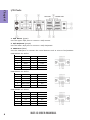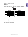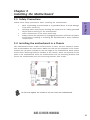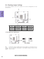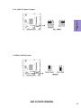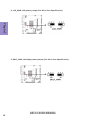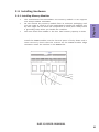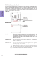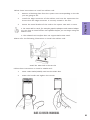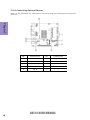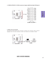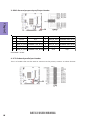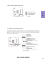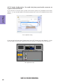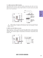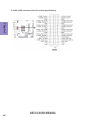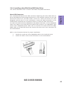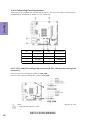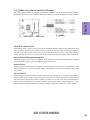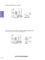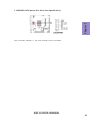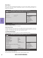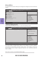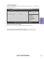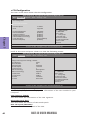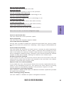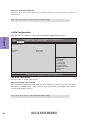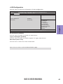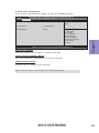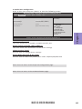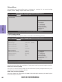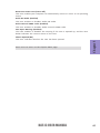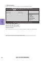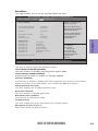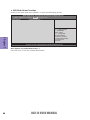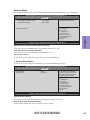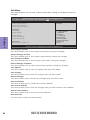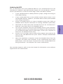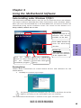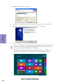
1
Preface Copyright This publication, including all photographs, illustrations and software, is protected under international copyright laws, with all rights reserved. Neither this manual, nor any of the material contained herein, may be reproduced without written consent of the author. Version 1.0 Disclaimer The information in this document is subject to change without notice. The manufacturer makes no representations or warranties with respect to the contents hereof and specifically disclaims any implied warranties of merchantability or fitness for any particular purpose. The manufacturer reserves the right to revise this publication and to make changes from time to time in the content hereof without obligation of the manufacturer to notify any person of such revision or changes. Trademark Recognition Microsoft, MS-DOS and Windows are registered trademarks of Microsoft Corp. MMX, Pentium, Pentium-II, Pentium-III, Celeron are registered trademarks of Intel Corporation. Other product names used in this manual are the properties of their respective owners and are acknowledged. Federal Communications Commission (FCC) This equipment has been tested and found to comply with the limits for a Class B digital device, pursuant to Part 15 of the FCC Rules. These limits are designed to provide reasonable protection against harmful interference in a residential installation. This equipment generates, uses, and can radiate radio frequency energy and, if not installed and used in accordance with the instructions, may cause harmful interference to radio communications. However, there is no guarantee that interference will not occur in a particular installation. If this equipment does cause harmful interference to radio or television reception, which can be determined by turning the equipment off and on, the user is encouraged to try to correct the interference by one or more of the following measures: • • • • Reorient or relocate the receiving antenna Increase the separation between the equipment and the receiver Connect the equipment onto an outlet on a circuit different from that to which the receiver is connected Consult the dealer or an experienced radio/TV technician for help Shielded interconnect cables and a shielded AC power cable must be employed with this equipment to ensure compliance with the pertinent RF emission limits governing this device. Changes or modifications not expressly approved by the system’s manufacturer could void the user’s authority to operate the equipment. BAT-I3 USER MANUAL Declaration of Conformity This device complies with part 15 of the FCC rules. Operation is subject to the following conditions: • This device may not cause harmful interference. • This device must accept any interference received, including interference that may cause undesired operation. This device is in conformity with the following EC/EMC directives: Limits and methods of mesurement of radio disturbance char EN 55022 acteristics of information technology equipment EN 61000-3-2 Disturbances in supply systems caused EN 61000-3-3 Disturbances in supply systems caused by household appliances and similar electrical equipment “ Voltage fluctuations” EN 55024 Information technology equipment-Immunity characteristicsLimits and methods of measurement Safety for information technology equipment including electrical business equipment EN 60950 CE marking Canadian Department of Communications This class B digital apparatus meets all requirements of the Canadian Interferencecausing Equipment Regulations. Cet appareil numérique de la classe B respecte toutes les exigences du Réglement sur le matériel brouilieur du Canada. About the Manual The manual consists of the following: Chapter 1 Introducing the Motherboard Describes features of the motherboard. page 1 Chapter 2 Installing the Motherboard Describes installation of motherboard components. page 9 Chapter 3 Using BIOS Provides information on using the BIOS Setup Utility. page 29 Chapter 4 Describes the motherboard Using the Motherboard Software software. page 65 Chapter 5 Trouble Shooting ii Provides basic trouble shoot- page 69 ing tips. BAT-I3 USER MANUAL TABLE OF CONTENTS Preface i Chapter 1 1 Introducing the Motherboard 1 Introduction...................................................................................1 Pakage Contents............................................................................1 Specifications................................................................................2 Motherboard Components..........................................................4 I/O Ports..............................................................................................6 Chapter 2 9 Installing the Motherboard 9 Safety Precautions.............................................................................9 Installing the Motherboard in a Chassis......................................9 Checking Jumper Settings..........................................................10 Installing Hardware...................................................................13 Installing Memory Modules....................................................13 Installing Add-on Cards...........................................................14 Connecting Optional Devices..................................................16 Installing a Hard Disk Drive/SATA Hard Drive.........................23 Connecting Case Components................................................24 Chapter 3 29 Using BIOS 29 About the Setup Utility........................ .......................................29 The Standard Configuration......................... ...........................29 Entering the Setup Utility........................................................29 Resetting the Default CMOS Values.....................................30 Using BIOS........................................................................................30 BIOS Navigation Keys..............................................................31 Main Menu.............................................................................32 Advanced Menu......................................................................34 Chipset Menu..........................................................................56 Boot Menu..............................................................................59 Security Menu.........................................................................61 Exit Menu................................................................................62 Updating the BIOS...................................................................63 BAT-I3 USER MANUAL iii Chapter 4 65 Using the Motherboard Software 65 Auto-installing under Windows 7/8/8.1....................................65 Running Setup.........................................................................65 Manual Installation..........................................................................67 Chapter 5 69 Trouble Shooting 69 Start up problems during assembly..............................................69 Start up problems after prolong use............................................70 Maintenance and care tips..............................................................70 Basic Troubleshooting Flowchart...................................................71 iv BAT-I3 USER MANUAL Introduction Thank you for choosing the BAT-I3 motherboard. This motherboard is a high performance, enhanced function. This motherboard has onboard Intel ® Bay Trail-D J2900/J1900/J1800 (10W) SoC for high-end business or personal desktop markets. Chapter 1 Chapter 1 Introducing the Motherboard This motherboard is based on Intel ® Bay Trail-D J2900/J1900/J1800 SoC for best desktop platform solution. It supports up to 8 GB of system memory with single channel DDR3L SO-DIMM 1333 MHz. One PCI slot and one full size Mini PCI Express and one half size Mini PCI Express slots are for extending usage. It implements an EHCI (Enhanced Host Controller Interface) compliant interface that provides five USB 2.0 ports (three USB 2.0 ports at the rear panel and one 10-pin USB 2.0 header supports two USB 2.0 ports) and one USB 3.0 port at the rear panel. The motherboard is equipped with advanced full set of I/O ports in the rear panel, including one PS/2 keyboard connector, one PS/2 mouse connector, two COM ports, one VGA port, one HDMI port, two RJ45 LAN connectors, three USB 2.0 ports, one USB 3.0 port and one audio jack for line-out and microphone. In addition, this motherboard supports one SATA 3Gb/s connector for expansion. Package Contents Your motherboard package ships with the following items: BAT-I3 Motherboard User Manual DVD I/O Shield 1 SATA Cable Accessories may vary, please refer to actual goods you purchase. BAT-I3 USER MANUAL 1 Chapter 1 Specifications Onboard Intel® Bay Trail-D J2900/J1900/J1800 (10W) SoC CPU • Chipset • Intel® Bay Trail-D J2900/J1900/J1800 SoC Memory • • • Single-channel DDR3L memory architecture 1 x 204-pin DDR3L SO-DIMM socket supports up to 8 GB Supports DDR3L SO-DIMM 1333 MHz Expansion Slots • • • 1 x PCI slot 1 x Full Size Mini PCIe slot (supports mSATA) 1 x Half Size Mini PCIe slot (supports WiFi/BT) Storage • Supported by Intel® Bay Trail-D J2900/J1900/J1800 SoC - 1 x Serial ATA 3Gb/s devices Audio • Realtek ALC662-VD0-GR 48P - 2 Channel High Definition Audio Codec - Compliant with HD audio specification LAN • Realtek RTL8111G+Intel I211 - 10/100/1000 Fast Ethernet Controller - wake-on-LAN and remote wake-up support Note: Please go to ECS website for the latest CPU support list. Note: Please go to ECS website for the latest Memory support list. 2 Rear Panel I/O • • • • • • • • 1 x PS/2 Keyboard connector and PS/2 Mouse connector 2 x COM ports 1 x VGA port 1 x HDMI port 2 x RJ45 LAN connectors 3 x USB 2.0 ports 1 x USB 3.0 port 1 x Audio jack for line-out and microphone Internal I/O • Connectors & • Headers • • • • • • • • • • • • • • • • • 1 x 4-pin 12V Power connector 1 x 4-pin CPU_FAN connector 1 x 4-pin SYS_FAN connector 1 x 10-pin USB 2.0 header supports two USB 2.0 ports 1 x Serial SATA 3Gb/s connector 1 x Front Panel switch/LED header 1 x Front Panel audio header 1 x Clear CMOS jumper 1 x Buzzer 2 x JCOM connectors (supports additional eight COM ports) 1 x LPT header 1 x General Purpose Input/Output header 1 x Analog audio input connector (CD_H) 1 x HDD Power connector 1 x SPK_L header 1 x SPK_R header 1 x LVDS connector (For All-In-One Specification) 1 x LVDS Power connector (For All-In-One Specification) 1 x LCD power jumper(For All-In-One Specification) BAT-I3 USER MANUAL 1 x Backlight power jumper(For All-In-One Specification) 1 x AC power jumper 1 x MONO jumper 1 x Case open header System BIOS • AMI BIOS with 64Mb SPI Flash ROM - Supports Plug and Play - Supports ACPI & DMI - Supports STR (S3) /STD (S4) - Supports Hardware monitor - Audio, LAN, can be disabled in BIOS - F7 hot key for boot up devices option - Supports PgUp clear CMOS Hotkey (Has PS2 KB Model only) Bundled Software Support • Supports Norton Anti Virus/Cyberlink Media Suite/Muzee Form Factor • Mini ITX Size, 170mm x 170mm BAT-I3 USER MANUAL Chapter 1 • • • • 3 Chapter 1 Motherboard Components Top View Bottom View 4 BAT-I3 USER MANUAL LABEL 1. CPU 2. SATA1 3. BZ 4. CPU_FAN 5. DIMM1 6. CLR_CMOS 7. JCOM3-6 & JCOM7-10 8. AC_PWR 9. GPIO 10. F_PANEL 11. CASE 12. MINIPCIE2 13. LPT 14. SYS_FAN 15. HDD PWR 16. PCI 17. SPK_L 18. CD_H 19. MONO 20. F_AUDIO 21. SPK_R 22. F_USB 23. LCD_PWR 24. BKLT_PWR 25. LVDSPWR 26. LVDS 27. ATX12V 28. BT1 29. SMINIPCIE1 COMPONENTS Onboard Intel® Bay Trail-D J2900/J1900/J1800 (10W) SoC Serial ATA 3Gb/s connector Buzzer 4-pin CPU cooling fan connector 204-pin DDR3L SDRAM SO-DIMM Clear CMOS jumper JCOM connectors (support additional eight COM ports) AC power jumper General purpose Input/Output header Front panel switch/LED header Case open header Half Size Mini PCI Express slot (supports WiFi/BT) Printer header 4-pin system cooling fan connector HDD power connector 32-bit add-on card slot Speaker Left header Analog audio input connector MONO jumper Front panel audio header Speaker Right header 10-pin USB 2.0 header supports two USB 2.0 ports LCD power jumper (For All-In-One Specification) Backlight power jumper (For All-In-One Specification) LVDS power connector(For All-In-One Specification) LVDS connector (For All-In-One Specification) 4-pin +12V power connector Battery Full Size Mini PCI Express slot (supports mSATA) BAT-I3 USER MANUAL Chapter 1 Table of Motherboard Components 5 Chapter 1 I/O Ports Intel LAN Realtek LAN 1. PS/2 Mouse (green) Use the upper PS/2 port to connect a PS/2 mouse. 2. PS/2 Keyboard (purple) Use the lower PS/2 port to connect a PS/2 keyboard. 3. COM Ports (blue) Use the COM ports to connect the serial devices such as mice or fax/modems. COM RS232 Pin Define Pin Define Pin Define 1 DCDN 6 DSRN 2 SINN 7 RTSN 3 SOUTN 8 CTSN 4 DTRN 9 RIN 5 GND COM RS422 Pin Define Pin Define Pin Define 1 RS422 TX(B) 6 N/A 2 RS422 TX(A) 7 N/A 3 RS422 RX(A) 8 N/A 4 RS422 RX(B) 9 N/A 5 N/A COM RS485 Pin Define 6 Pin Define Pin Define 1 RS485 D-(B) 6 N/A 2 RS485 D+(A) 7 N/A 3 N/A 8 N/A 4 N/A 9 N/A 5 N/A BAT-I3 USER MANUAL 5. HDMI Port Connect display device to the HDMI port. 6. LAN Ports Connect an RJ-45 jack to the LAN port to connect your computer to the Network. Chapter 1 4. VGA Port Connect your monitor to the VGA port. Link LED LAN Port Intel LAN Transmission Speed LAN LED Activity LED 100M Link LED Activity LED Giga Link LED Realtek LAN Status Description OFF No data Green blinking Active OFF No link Green Link OFF No data Green blinking Active OFF No link Green Link Transmission Speed LAN LED Activity LED 100M Link LED Activity LED Giga Link LED Status Description OFF No data Orange blinking Active OFF No link Green Link OFF No data Orange blinking Active OFF No link Green Link 7. USB 3.0 Ports Use the USB 3.0 ports to connect USB 3.0 devices. 8. USB 2.0 Ports Use the USB 2.0 ports to connect USB 2.0 devices. 9. Line-out (lime) It is used to connect to speakers or headphones. 10. Microphone (pink) It is used to connect to a microphone. BAT-I3 USER MANUAL 7 Chapter 1 8 Memo BAT-I3 USER MANUAL Chapter 2 Installing the Motherboard Follow these safety precautions when installing the motherboard: • • • • Wear a grounding strap attached to a grounded device to avoid damage from static electricity. Discharge static electricity by touching the metal case of a safely grounded object before working on the motherboard. Leave components in the static-proof bags. Always remove the AC power by unplugging the power cord from the power outlet before installing or removing the motherboard or other hardware components. Chapter 2 2-1. Safety Precautions 2-2. Installing the motherboard in a Chassis This motherboard carries a Mini ITX form factor of 170 x 170 mm. Choose a chassis that accommodates this from factor. Make sure that the I/O template in the chassis matches the I/O ports installed on the rear edge of the motherboard. Most system chassis have mounting brackets installed in the chassis, which corresponds to the holes in the motherboard. Place the motherboard over the mounting brackets and secure the motherboard onto the mounting brackets with screws. Do not over-tighten the screws as this can stress the motherboard. BAT-I3 USER MANUAL 9 2-3. Checking Jumper Settings This section explains how to set jumpers for correct configuration of the motherboard. Chapter 2 No. Components No. 1 CLR_CMOS 4 Components LCD_PWR 2 AC_PWR 5 BKLT_PWR 3 MONO ~~ ~~ 1. CLR_CMOS: Clear CMOS jumper To avoid the system instability after clearing CMOS, we recommend users to enter the main BIOS setting page to “Load Default Settings” and then “Save and Exit Setup”. 10 BAT-I3 USER MANUAL Chapter 2 2. AC_PWR: AC power jumper 3. MONO: MONO jumper BAT-I3 USER MANUAL 11 4. LCD_PWR: LCD power jumper (For All-In-One Specification) Chapter 2 5. BKLT_PWR : Backlight power jumper (For All-In-One Specification) 12 BAT-I3 USER MANUAL 2-4. Installing Hardware • • • This motherboard accommodates one memory module. It can support one 204-pin DDR3L 1333 MHz. Do not remove any memory module from its antistatic packaging until you are ready to install it on the motherboard. Handle the modules only by their edges. Do not touch the components or metal parts. Always wear a grounding strap when you handle the modules. You must install one module in the slot. Total memory capacity is 8 GB. Chapter 2 2-4-1. Installing Memory Modules Install the DIMM module into the slot and press it firmly down until it seats correctly. Check that the cutouts on the DIMM module edge connector match the notches in the DIMM slot. BAT-I3 USER MANUAL 13 2-4-2. Installing Add-on Cards The slots on this motherboard are designed to hold expansion cards and connect them to the system bus. Expansion slots are a means of adding or enhancing the motherboard’s features and capabilities. With these efficient facilities, you can increase the motherboard’s capabilities by adding hardware that performs tasks that are not part of the basic system. Chapter 2 Top View Bottom View PCI Slot This motherboard is equipped with one standard PCI slot. PCI stands for Peripheral Component Interconnect and is a bus standard for expansion cards, which for the most part, is a supplement of the older ISA bus standard. The PCI slots on this board are PCI V3.0. SMINIPCIE1 Slot The mini PCIE (full-card) supports SATA signal for extending usage of mSATA card. MINIPCIE2 Slot The mini PCIE (half-card) supports USB signal and PCIe signal for extending usage of BT and Wifi. Before installing an add-on card, check the documentation for the card carefully. If the card is not Plug and Play, you may have to manually configure the card before installation. 14 BAT-I3 USER MANUAL 1 Remove a blanking plate from the system case corresponding to the slot you are going to use. 2 Install the edge connector of the add-on card into the expansion slot. Ensure that the edge connector is correctly seated in the slot. 3 Secure the metal bracket of the card to the system case with a screw. 1. For some add-on cards, for example graphics adapters and network adapters, you have to install drivers and software before you can begin using the add-on card. Chapter 2 Follow these instructions to install an add-on card: 2. The onboard PCI interface does not support 64-bit SCSI cards. Please refer the following illustrations to install the add-on card: Install the VGA Card in the PCI slot Follow these instructions to install a mSATA card : 1 Insert a Mini SATA (mSATA) card into the PCIE1 Slot. 2 Lower the handle and tighten the screws. BAT-I3 USER MANUAL 15 2-4-3. Connecting Optional Devices Refer to the following for information on connecting the motherboard’s optional devices: Chapter 2 16 No. Components No. Components 1 JCOM3-6 & JCOM7-10 6 F_AUDIO 2 CASE 7 F_USB 3 GPIO 8 SATA1 4 LPT 9 LVDS 5 CD_H ~~ ~~ BAT-I3 USER MANUAL Chapter 2 1. JCOM3-6/JCOM7-10: JCOM connectors (support additional eight COM ports) 2. CASE: Case open header This detects if the chassis cover has been removed. This function needs a chassis equipped with instrusion detection switch and needs to be enabled in BIOS. BAT-I3 USER MANUAL 17 3. GPIO: General purpose Input/Output header Chapter 2 Pin Define Address/Bit Pin 1 VCC 5V N/A 2 GPIO_S0_SC17 GPIOBASE + 08h, Bit 17 Define Address/Bit 3 GPIO_S0_SC21 GPIOBASE + 08h, Bit 21 4 GPIO_S0_SC18 GPIOBASE + 08h, Bit 18 5 GPIO_S0_SC22 GPIOBASE + 08h, Bit 22 6 GPIO_S0_SC19 GPIOBASE + 08h, Bit 19 7 GPIO_S0_SC23 GPIOBASE + 08h, Bit 23 8 GPIO_S0_SC20 GPIOBASE + 08h, Bit 20 9 GPIO_S0_SC24 GPIOBASE + 08h, Bit 24 10 GND N/A GPIOBASE: 0x500 4. LPT: Onboard parallel port header This is a header that can be used to connect to the printer, scanner or other devices. 18 BAT-I3 USER MANUAL Chapter 2 5. CD_H: Analog audio input connector 6. F_AUDIO: Front Panel Audio Header The front panel audio header allows the user to install auxiliary front-oriented microphone and line-out ports for easier access. This header supports HD audio by default. If you want connect an AC’ 97 front panel audio to HD onboard headers, please set as below picture. BAT-I3 USER MANUAL 19 AC’ 97 Audio Configuration: To enable the front panel audio connector to support AC97 Audio mode. If you use AC’ 97 Front Panel, please tick off the option of “ Disabled Front Panel Detect ”. If you use HD Audio Front Panel, please don’ t tick off “Disabled Front Panel Detect ” . Chapter 2 * For reference only If you use AC’ 97 Front Panel, please don’ t tick off “Using Front Jack Detect ”. If you use HD Audio Front Panel, please tick off the option of “Using Front Jack Detect ”. * For reference only 20 BAT-I3 USER MANUAL 7. F_USB: Front Panel USB 2.0 header Chapter 2 The motherboard has one USB 2.0 header supporting two USB 2.0 ports. Additionally, some computer cases have USB ports at the front of the case. If you have this kind of case, use auxiliary USB connector to connect the front-mounted ports to the motherboard. Please make sure that the USB cable has the same pin assignment as indicated above. A different pin assignment may cause damage or system hang-up. 8. SATA1: Serial ATA 3Gb/s connector SATA1 connector is used to support the Serial ATA 3Gb/s device, simpler disk drive cabling and easier PC assembly. It eliminates limitations of the current Parallel ATA interface. But maintains register compatibility and software compatibility with Parallel ATA. BAT-I3 USER MANUAL 21 9. LVDS: LVDS connector (For All-In-One Specification) Chapter 2 22 BAT-I3 USER MANUAL 2-4-4. Installing a Hard Disk Drive/SATA Hard Drive This section describes how to install a Hard Disk Drive/SATA Hard Drive. Your motherboard features one SATA connector supporting one drive. SATA refers to Serial ATA (Advanced Technology Attachment) is the standard interface for the IDE hard drives which are currently used in most PCs. These connectors are well designed and will only fit in one orientation. Locate the SATA connectors on the motherboard and follow the illustration below to install the SATA hard drives. To install the Hard Disk Drive (HDD)/Serial ATA (SATA) hard drives, use the HDD/SATA cable that supports the Hard Disk Drive/Serial ATA protocol. This HDD/SATA cable comes with a HDD/SATA power cable. You can connect the comb end of the HDD/ SSATA cable to the Hard Disk Drive and connect the other end to the connectors on the motherboard. Chapter 2 About SATA Connectors Refer to the illustration below for proper installation: 1 2 Attach the comb end of the HDD/SATA cable to the Hard Disk Drive. Attach the other ends to the connectors on the motherboard. BAT-I3 USER MANUAL 23 2-4-5. Connecting Case Components After you have installed the motherboard into a case, you can begin connecting the motherboard components. Refer to the following: Chapter 2 No. Components No. 1 CPU_FAN 5 Components SPK_L 2 F_PANEL 6 SPK_R 3 SYS_FAN 7 LVDSPWR 4 HDD_PWR ~ ~ 1 & 3. CPU_FAN (CPU cooling FAN connector) & SYS_FAN (System cooling FAN connector) Connect the CPU cooling fan cable to CPU_FAN. Connect the system cooling fan cable to SYS_FAN. Users please note that the fan connector supports the CPU cooling fan of 1.1A ~ 2.2A (26.4W max) at +12V. 24 BAT-I3 USER MANUAL 2. F_PANEL: Front Panel switch/LED header Chapter 2 The front panel header (F_PANEL) provides a standard set of switch and LED headers commonly found on ATX or Micro ATX cases. Refer to the table below for information: Hard Drive Activity LED Connecting pins 1 and 3 to a front panel mounted LED provides visual indication that data is being read from or written to the hard drive. For the LED to function properly, an IDE drive should be connected to the onboard IDE interface. The LED will also show activity for devices connected to the SCSI (hard drive activity LED) connector. Power/Sleep/Message waiting LED Connecting pins 2 and 4 to a single or dual-color, front panel mounted LED provides power on/off, sleep, and message waiting indication. Reset Switch Supporting the reset function requires connecting pin 5 and 7 to a momentary-contact switch that is normally open. When the switch is closed, the board resets and runs POST. Power Switch Supporting the power on/off function requires connecting pins 6 and 8 to a momentary-contact switch that is normally open. The switch should maintain contact for at least 50 ms to signal the power supply to switch on or off. The time requirement is due to internal de-bounce circuitry. After receiving a power on/off signal, at least two seconds elapses before the power supply recognizes another on/off signal. BAT-I3 USER MANUAL 25 4. HDD_PWR: HDD power connector Chapter 2 5 & 6. SPK_L & SPK_R: Speaker Left header & Speaker Right header Connect the case speaker cable to SPK_L & SPK_R. 26 BAT-I3 USER MANUAL Chapter 2 7. LVDSPWR: LVDS power (For-All-In-One Specification) This concludes Chapter 2. The next chapter covers the BIOS. BAT-I3 USER MANUAL 27 Memo Chapter 2 28 BAT-I3 USER MANUAL Chapter 3 Using BIOS About the Setup Utility The BIOS (Basic Input and Output System) Setup Utility displays the system’s configuration status and provides you with options to set system parameters. The parameters are stored in battery-backed-up CMOS RAM that saves this information when the power is turned off. When the system is turned back on, the system is configured with the values you stored in CMOS. The BIOS Setup Utility enables you to configure: • Hard drives, diskette drives and peripherals • Video display type and display options • Password protection from unauthorized use • Power Management features Chapter 3 The computer uses the latest “American Megatrends Inc. ” BIOS with support for Windows Plug and Play. The CMOS chip on the motherboard contains the ROM setup instructions for configuring the motherboard BIOS. The settings made in the Setup Utility affect how the computer performs. Before using the Setup Utility, ensure that you understand the Setup Utility options. This chapter provides explanations for Setup Utility options. The Standard Configuration A standard configuration has already been set in the Setup Utility. However, we recommend that you read this chapter in case you need to make any changes in the future. This Setup Utility should be used: • when changing the system configuration • when a configuration error is detected and you are prompted to make changes to the Setup Utility • when trying to resolve IRQ conflicts • when making changes to the Power Management configuration • when changing the password or making other changes to the Security Setup Entering the Setup Utility When you power on the system, BIOS enters the Power-On Self Test (POST) routines. POST is a series of built-in diagnostics performed by the BIOS. After the POST routines are completed, the following message appears: Press DEL to enter SETUP BAT-I3 USER MANUAL 29 Press the delete key to access BIOS Setup Utility. Aptio Setup Utility - Copyright (C) 2013 American Megatrends, Inc. Main Advanced Chipset Boot Security Exit Choose the system default language BIOS Information System Language [English] System Date System Time [Fri 08/22/2014] [01:43:56] Product Information :Select Screen :Select Item Chapter 3 Enter : Select +/- : Change Opt. F1:General Help F2:Previous Values F3:Optimized Defaults F4:Save & Exit ESC:Exit Version 2.16.1242. Copyright (C) 2013 American Megatrends, Inc. Resetting the Default CMOS Values When powering on for the first time, the POST screen may show a “CMOS Settings Wrong” message. This standard message will appear following a clear CMOS data at factory by the manufacturer. You simply need to Load Default Settings and Save it to reset the default CMOS values. Note: Changes to system hardware such as different CPU, memories, etc. may also trigger this message. Using BIOS When you start the Setup Utility, the main menu appears. The main menu of the Setup Utility displays a list of the options that are available. A highlight indicates which option is currently selected. Use the cursor arrow keys to move the highlight to other options. When an option is highlighted, execute the option by pressing <Enter>. Some options lead to pop-up dialog boxes that prompt you to verify that you wish to execute that option. Other options lead to dialog boxes that prompt you for information. Some options (marked with a triangle ) lead to submenus that enable you to change the values for the option. Use the cursor arrow keys to scroll through the items in the submenu. 30 BAT-I3 USER MANUAL In this manual, default values are enclosed in parenthesis. Submenu items are denoted by a triangle . The default BIOS setting for this motherboard apply for most conditions with optimum performance. We do not suggest users change the default values in the BIOS setup and take no responsibility to any damage caused by changing the BIOS settings. BIOS Navigation Keys The BIOS navigation keys are listed below: KEY +/Enter FUNCTION Exits the current menu Scrolls through the items on a menu Change Opt. Select F1 General Help F2 Previous Value F3 Optimized Defaults F4 Save & Exit Chapter 3 ESC For the purpose of better product maintenance, the manufacture reserves the right to change the BIOS items presented in this manual. The BIOS setup screens shown in this chapter are for reference only and may differ from the actual BIOS. Please visit the manufacture’s website for updated manual. BAT-I3 USER MANUAL 31 Main Menu When you enter the BIOS Setup program, the main menu appears, giving you an overview of the basic system information. Select an item and press <Enter> to display the submenu. Aptio Setup Utility - Copyright (C) 2013 American Megatrends, Inc. Main Advanced Chipset Boot Security Exit Choose the system default language BIOS Information System Language [English] System Date System Time [Fri 08/22/2014] [01:43:56] Chapter 3 Product Information :Select Screen :Select Item Enter : Select +/- : Change Opt. F1:General Help F2:Previous Values F3:Optimized Defaults F4:Save & Exit ESC:Exit Version 2.16.1242. Copyright (C) 2013 American Megatrends, Inc. System Language (English) This item is used to set system language. System Date & Time The Date and Time items show the current date and time on the computer. If you are running a Windows OS, these items are automatically updated whenever you make changes to the Windows Date and Time Properties utility. Product Information Scroll to this item and press <Enter> to view the following screen: Aptio Setup Utility - Copyright (C) 2013 American Megatrends, Inc. Main Advanced Chipset Boot Security Exit Product Information System Overview System Product Name M/B Product Name Serial Number System Manufacturer System BIOS Version BIOS Release Date Asset Tag BAT-I3 BAT-I3 00000000 ECS 1.0 08/22/2014 To Be Filled By O.E.M. Processor Intel(R) Celeron(R) CPU J1900 @ 1.99GHz Processor Speed 2.00 GHz System Memory Memory Frequency Total Memory 1333 MHz 4096 MB (LPDDR3) :Select Screen :Select Item Enter : Select +/- : Change Opt. F1:General Help F2:Previous Values F3:Optimized Defaults F4:Save & Exit ESC:Exit Version 2.16.1242. Copyright (C) 2013 American Megatrends, Inc. System Product Name (BAT-I3) This item shows the information of the system product name. 32 BAT-I3 USER MANUAL BIOS Release Date (08/22/2014) This item shows the information of the BIOS release date. Asset Tag (To Be Filled By O.E.M.) This item shows the information of the serial tag. Intel(R) Celeron(R) CPU J1900 @ 1.99GHz This is display-only field and diaplays the information of the CPU installed in your computer. Processor Speed (2.00 GHz) This item shows the information of the processor speed. Memory Frequency (1333 MHz) This item shows the information of the memory frequency. Total Memory (4096 MB (LPDDR3)) This item shows the information of the total memory. BAT-I3 USER MANUAL Chapter 3 M/B Product Name (BAT-I3) This item shows the information of the system product name. Serial Number (00000000) This item shows the information of the serial number. System Manufacturer (ECS) This item shows the information of the system system manufacturer. System BIOS Version (1.0) This item shows the information of the system BIOS version. 33 Advanced Menu The Advanced menu items allow you to change the settings for the CPU and other system. Main Aptio Setup Utility - Copyright (C) 2013 American Megatrends, Inc. Advanced Chipset Boot Security Exit Chapter 3 Memory Voltage Control LAN Configuration Power Management Setup PC Health Status PCI Express Configuration ACPI Settings CPU Configuration SATA Configuration USB Configuration Intel(R) Smart Connect Technology Super IO Configuration Memory Voltage Control :Select Screen :Select Item Enter : Select +/- : Change Opt. F1:General Help F2:Previous Values F3:Optimized Defaults F4:Save & Exit ESC:Exit Version 2.16.1242. Copyright (C) 2013 American Megatrends, Inc. Memory Voltage Control Scroll to this item and press <Enter> to view the following screen: Aptio Setup Utility - Copyright (C) 2013 American Megatrends, Inc. Main Advanced Chipset Boot Security Exit Memory Voltage Control Memory Voltage Configuration [Auto] Auto: Lowest voltage supported by memory modules Low Voltage: DDR3L standard voltage Manual: User customized :Select Screen :Select Item Enter : Select +/- : Change Opt. F1:General Help F2:Previous Values F3:Optimized Defaults F4:Save & Exit ESC:Exit Version 2.16.1242. Copyright (C) 2013 American Megatrends, Inc. Memory Voltage Configuration (Auto) This item provides 3 configuration modes for the voltage of memory modules. Auto:Always provide DDR3L standard voltage (1.35V). Low Voltage: Provide the lowestvoltage memory module supported. Manual: User customized (provide 1.35V or1.50V). Press <Esc> to return to the Advanced Menu page. 34 BAT-I3 USER MANUAL LAN Configuration The item in the menu shows the LAN-related information that the BIOS automatically detects. Aptio Setup Utility - Copyright (C) 2013 American Megatrends, Inc. Main Advanced Chipset Boot Security Exit Enabled/Disabled Onboard LAN 1 Controller Onboard LAN 1 Controller [Enabled] Onboard LAN 2 Controller [Enabled] :Select Screen :Select Item Enter : Select +/- : Change Opt. F1:General Help F2:Previous Values F3:Optimized Defaults F4:Save & Exit ESC:Exit Version 2.16.1242. Copyright (C) 2013 American Megatrends, Inc. Chapter 3 LAN Configuration Onboard LAN 1/2 Controller (Enabled) Use these items to enable or disable Onboard LAN 1/2 controller. Press <Esc> to return to the Advanced Menu page. BAT-I3 USER MANUAL 35 Power Management Setup This page sets up some parameters for system power management operation. Main Aptio Setup Utility - Copyright (C) 2013 American Megatrends, Inc. Advanced Chipset Boot Security Exit Power Management Setup Resume By PME Resume By USB Resume By PS2 KB Resume By PS2 MS Resume By RTC Alarm EUP Function Power LED Type [Disabled] [Disabled] [Disabled] [Disabled] [Disabled] [Enabled] [Dual Color LED] About Resume by PCI/PCI-E/LAN/Ext .USB3.0 PME :Select Screen :Select Item Chapter 3 Enter : Select +/- : Change Opt. F1:General Help F2:Previous Values F3:Optimized Defaults F4:Save & Exit ESC:Exit Version 2. 16.1242. Copyright (C) 2013 American Megatrends, Inc. Resume By PME (Disabled) This item specify whether the system will be awakened from power saving modes when activity or input signal of the specified hardware peripheral or components is detected. Resume By USB (Disabled) This item allows you to enable/disable the USB device wakeup function from S3 mode. Resume By PS2 KB (Disabled) This item enables or disables you to allow keyboard activity to awaken the system from power saving mode. Resume By PS2 MS (Disabled) This item enables or disables you to allow mouse activity to awaken the system from power saving mode. Resume By RTC Alarm (Disabled) This item can be turned off with a software command. If you enable this item, the system can automatically resume at a fixed time based on the system’s RTC (realtime clock). Use the items below this one to set the date and time of the wake-up alarm. You must use an ATX power supply in order to use this feature. EUP Function (Enabled) This item allows user to enable or disable EUP support. Power LED Type (Dual Color LED) This item shows the type of the power LED. Press <Esc> to return to the Advanced Menu page. 36 BAT-I3 USER MANUAL PC Health Status On motherboards support hardware monitoring, this item lets you monitor the parameters for critical voltages, temperatures and fan speeds. Aptio Setup Utility - Copyright (C) 2013 American Megatrends, Inc. Main Advanced Chipset Boot Security Exit PC Health Status Smart Fan Function 41 37O C 5037 RPM 0 RPM 0.864 V 1.380 V TCC Activation Temperature (DTS) 105 :Select Screen :Select Item Enter : Select +/- : Change Opt. F1:General Help F2:Previous Values F3:Optimized Defaults F4:Save & Exit ESC:Exit Version 2.16.1242. Copyright (C) 2013 American Megatrends, Inc. Smart Fan Function Scroll to this item and press <Enter> to view the following screen: Main Chapter 3 CPU Temperature (DTS) System Temperature CPU Fan Speed System Fan Speed CPU Voltage DIMM Voltage Aptio Setup Utility - Copyright (C) 2013 American Megatrends, Inc. Advanced Chipset Boot Security Exit CPU Smart Fan Control Smart Fan Mode [Enabled] [Normal] Smart Fan start PWM value Smart Fan start PWM TEMP (DTS) DeltaT Smart Fan Slope PWM value CPU Fan Full Speed Offset (DTS) 180 70 +3 10 PWM value / unit 77 System Smart Fan Control Smart Fan Mode [Enabled] [Normal] Smart Fan start PWM value Smart Fan start PWM TEMP (DTS) DeltaT Smart Fan Slope PWM value System Fan Full Speed Offset (DTS) 180 70 +3 10 PWM value / unit 77 Enable CPU SmartFan :Select Screen :Select Item Enter : Select +/- : Change Opt. F1:General Help F2:Previous Values F3:Optimized Defaults F4:Save & Exit ESC:Exit Version 2.16.1242. Copyright (C) 2013 American Megatrends, Inc. CPU/System Smart Fan Control (Enabled) This item allows you to enable or disable the control of the CPU fan speed by changing the fan voltage. Smart Fan Mode (Normal) This item allows you to select the fan mode (Normal, Quiet, Silent, or Manual) for a better operation environment. If you choose Normal mode, the fan speed will be auto adjusted depending on the CPU temperature. If you choose Quiet mode, the fan speed will be auto minimized for quiet environment. If you choose Silent mode, the fan speed will be auto restricted to make system more quietly. If you choose Manual mode, the fan speed will be adjust depending on users’ parameters. BAT-I3 USER MANUAL 37 SMART Fan start PWM value (180) This item is used to set the start PWM value of the smart fan. SMART Fan start TEMP (DTS) (70) This item is used to set the start temperature of the smart fan. DeltaT (+3) This item specifies the range that controls CPU temperature and keeps it from going so high or so low when smart fan works. Smart Fan Slope PWM value (10 PWM value / unite) This item is used to set the Slope Select PWM of the smart fan. CPU/System Fan Full Speed Offset (DTS) (77) This item is used to set the CPU/System fan full speed offset value. Chapter 3 Press <Esc> to return to the PC Health Status page. System Component Characteristics These items display the monitoring of the overall inboard hardware health events, such as System temperature, CPU & DIMM voltage, CPU & System fan speed... etc. • • • • • • CPU Temperature (DTS) System Temperature CPU Fan Speed System Fan Speed CPU Voltage DIMM Voltage Press <Esc> to return to the Advanced Menu page. 38 BAT-I3 USER MANUAL PCI Express Configuration The item in the menu shows the information of PCI Express Configuration. Main Aptio Setup Utility - Copyright (C) 2013 American Megatrends, Inc. Advanced Chipset Boot Security Exit PCI Express Configuration mPCIE Speed [Auto] Configure PCIE slot Speed Enter : Select +/- : Change Opt. F1:General Help F2:Previous Values F3:Optimized Defaults F4:Save & Exit ESC:Exit Version 2.16.1242. Copyright (C) 2013 American Megatrends, Inc. mPCIE Speed (Auto) This item allows user to configure the mPCIE speed. Chapter 3 :Select Screen :Select Item Press <Esc> to return to the Advanced Menu page. ACPI Settings The item in the menu shows the highest ACPI sleep state when the system enters suspend. Main Aptio Setup Utility - Copyright (C) 2013 American Megatrends, Inc. Advanced Chipset Boot Security Exit ACPI Settings ACPI Sleep State [S3 (Suspend to RAM)] Select the highest ACPI sleep state the system will enter when the SUSPEND button is pressed. :Select Screen :Select Item Enter : Select +/- : Change Opt. F1:General Help F2:Previous Values F3:Optimized Defaults F4:Save & Exit ESC:Exit Version 2.16.1242. Copyright (C) 2013 American Megatrends, Inc. ACPI Sleep State [S3(Suspend to RAM)] This item allows user to enter the ACPI S3 (Suspend to RAM) Sleep State (default). Press <Esc> to return to the Advanced Menu page. BAT-I3 USER MANUAL 39 CPU Configuration The item in the menu shows the CPU Configuration. Main Aptio Setup Utility - Copyright (C) 2013 American Megatrends, Inc. Advanced Chipset Boot Security Exit Socket specific CPU Information CPU Configuration Socket 0 CPU Information Chapter 3 Processor Speed 64-bit 2.00 GHz Supported Limit CPUID Maximum Execute Disable Bit Hardware Prefetcher Adjacent Cache Line Prefetch Intel Virtualization Technology Power Technology Enhanced Halt (C1E) [Disabled] [Enabled] [Enabled] [Enabled] [Enabled] [Energy Efficient] [Enabled] :Select Screen :Select Item Enter : Select +/- : Change Opt. F1:General Help F2:Previous Values F3:Optimized Defaults F4:Save & Exit ESC:Exit Version 2.16.1242. Copyright (C) 2013 American Megatrends, Inc. Socket 0 CPU Information Scroll to this item and press <Enter> to view the following screen: Main Aptio Setup Utility - Copyright (C) 2013 American Megatrends, Inc. Advanced Chipset Boot Security Exit Socket 0 CPU Information Intel(R) Celeron(R) CPU J1900 @ 1.99GHz CPU Signature 30678 Microcode Patch 811 Max CPU Speed 2000 MHz Min CPU Speed 1333 MHz Processor Cores 4 Intel HT Technology Not Supported Intel VT-x Technology Supported L1 Data Cache L1 Code Cache L2 Cache L3 Cache 24 kB x 4 32 kB x4 1024 kB x 2 Not Present :Select Screen :Select Item Enter : Select +/- : Change Opt. F1:General Help F2:Previous Values F3:Optimized Defaults F4:Save & Exit ESC:Exit Version 2.16.1242. Copyright (C) 2013 American Megatrends, Inc. Intel(R) Celeron(R) CPU J1900 @ 1.99GHz This is display-only field and diaplays the information of the CPU installed in your computer. CPU Signature (30678) This item shows the information of the CPU signature. Microcode Patch (811) This item shows the version of Microcode patch. Max CPU Speed (2000 MHz) This item shows the max speed of the CPU. 40 BAT-I3 USER MANUAL Press <Esc> to return to the CPU Configuration page. Chapter 3 Min CPU Speed (1333 MHz) This item shows the min speed of the CPU. Processor Cores (4) This item shows the number of cores of the processor. Intel HT Technology (Not Supported) This item shows the supports Intel HT technology or not. Intel VT-x Technology (Supported) This item shows the supports Intel VT-x technology or not. L1 Data Cache (24 kB x 4) This item shows the size of CPU L1 Data Cache memory. L1 Code Cache (32 kB x 4) This item shows the size of CPU L1 Code Cache memory. L2/L3 Cache (1024 kB x 2/Not Present) These items show the size of CPU L2/L3 Cache memory. Processor Speed (2.00 GHz) This item shows the current processor speed. 64-bit (Supported) This item shows the computer supports EMT64. Limit CPUID Maximum (Disabled) Use this item to enable or disable the maximum CPUID value limit, you can enable this item to prevent the system from “rebooting” when trying to install Windows NT 4.0. Excute Disable Bit (Enabled) This item allows the processor to classify areas in memory by where application code can execute and where it cannot. When a malicious worm attempts to insert code in the buffer, the processor disables code execution, preventing damage or worm propagation. Replacing older computers with Execute Disable Bit enabled systems can halt worm attacks, reducing the need for virus related repair. Hardware Prefetcher (Enabled) If you enable this item, the processor fetches data and instructions from the memoryinto the cache that are likely to be required in the near future. This reduces thelatency associated with memory reads. Adjacent Cache Line Prefetch (Enabled) If you enable this item, the processor fetches the currently requested cache line, aswell as the subsequent cache line. This reduces the cache latency by making thenext cache line immediately avaiable if the processor requires it as well. Intel Virtualization Technology (Enabled) When disabled, a VMM cannot utilize the additional hardware capabilities provided by Vandor Pool Technology. Power Technology (Energy Efficient) This item enables or disables the power management features. BAT-I3 USER MANUAL 41 Enhanced Halt (CIE) (Enabled) Use this item to enable the CPU energy-saving function when the system is notrunning. Press <Esc> to return to the Advanced Menu page. SATA Configuration Use this item to show the mode of serial SATA configuration options. Chapter 3 Aptio Setup Utility - Copyright (C) 2013 American Megatrends, Inc. Main Advanced Chipset Boot Security Exit Select IDE / AHCI SATA Configuration SATA Mode [AHCI Mode] SATA Port mSATA Not Present Not Present :Select Screen :Select Item Enter : Select +/- : Change Opt. F1:General Help F2:Previous Values F3:Optimized Defaults F4:Save & Exit ESC:Exit Version 2.16.1242. Copyright (C) 2013 American Megatrends, Inc. SATA Mode (AHCI Mode) Use this item to select SATA mode. SATA Port/mSATA (Not Present) This motherboard supports one SATA and one mSATA channels, each channel allows one SATA or mSATA device to be installed. Use these items to configure each device on the SATA/mSATA channel. Press <Esc> to return to the Advanced Menu page. 42 BAT-I3 USER MANUAL USB Configuration Use this item to show the information of USB configuration. Aptio Setup Utility - Copyright (C) 2013 American Megatrends, Inc. Main Advanced Chipset Boot Security Exit USB Configuration USB Support Parameters [Enabled] [Enabled] [Smart Auto] :Select Screen :Select Item Enter : Select +/- : Change Opt. F1:General Help F2:Previous Values F3:Optimized Defaults F4:Save & Exit ESC:Exit Version 2.16.1242. Copyright (C) 2013 American Megatrends, Inc. All USB Devices (Enabled) Use this item to enable or disable all USB devices. Legacy USB Support (Enabled) Use this item to enable or disable support for legacy USB devices. XHCI Mode (Smart Auto) Use this item to select the mode of USB XHCI. Chapter 3 All USB Devices Legacy USB Support XHCI Mode Press <Esc> to return to the Advanced Menu page. BAT-I3 USER MANUAL 43 Intel(R) Smart Connect Technology Use this item to show the information of Intel(R) Smart connect technology. Aptio Setup Utility - Copyright (C) 2013 American Megatrends, Inc. Main Advanced Chipset Boot Security Exit ISCI Support [Disabled] Enable/Disable ISCI Support :Select Screen :Select Item Chapter 3 Enter : Select +/- : Change Opt. F1:General Help F2:Previous Values F3:Optimized Defaults F4:Save & Exit ESC:Exit Version 2.16.1242. Copyright (C) 2013 American Megatrends, Inc. ISCT Support (Disabled) Use this item to enable or disable ISCT Support. Press <Esc> to return to the Advanced Menu page. 44 BAT-I3 USER MANUAL Aptio Setup Utility - Copyright (C) 2013 American Megatrends, Inc. Main Advanced Chipset Boot Security Exit Main Advanced Chipset M.I.B III Boot Security Exit Set Parameters of Serial Port Super IO Configuration 1 (COMA) Super IO Chip IT8786, IT8768 Serial Port 1 Configutation Serial Port 2 Configuration :Select Screen Serial Port 3 Configuration :Select Item Serial Port 4 Configuration Enter : Select Serial Port 5 Configuration +/- : Change Opt. Serial Port 6 Configuration Serial Port 7 Configuration F1:General Help Serial Port 8 Configuration F2:Previous Values Serial Port 9 Configuration F3:Optimized Defaults Serial Port 10 Configuration F4:Save & Exit Parallel Port Configuration ESC:Exit Version 2.16.1242. Copyright (C) 2013 American Megatrends, Inc. Super IO Chip (IT8786, IT8768) This item shows the information of the super IO chip. Serial Port 1 Configuration Scroll to this item and press <Enter> to view the following screen: Chapter 3 Super IO Configuration Use this item to show the information of Super IO configuration. Aptio Setup Utility - Copyright (C) 2013 American Megatrends, Inc. Advanced Chipset Chipset Tweak Boot Boot Security Exit Main Advanced Main Security Exit Serial Port 1 Configuration Serial Port Device Settings [Enabled] IO=3F8h; IRQ=4; Change Settings [Auto] Enable or Disable Serial Port (COM) :Select Screen :Select Item Enter : Select +/- : Change Opt. F1:General Help F2:Previous Values F3:Optimized Defaults F4:Save & Exit ESC:Exit Version 2.16.1242. Copyright (C) 2013 American Megatrends, Inc. Serial Port (Enabled) This item allows you to enable or disable serial port. Device Settings (IO=3F8h; IRQ=4) This item shows the information of the device settings. Change Settings (Auto) Use this item to change device settings. Press <Esc> to return to the Super IO Configuration page. BAT-I3 USER MANUAL 45 Serial Port 2 Configuration Scroll to this item and press <Enter> to view the following screen: Main Aptio Setup Utility - Copyright (C) 2013 American Megatrends, Inc. Advanced Chipset Boot Security Exit Serial Port 2 Configuration Serial Port Device Settings [Enabled] IO=2F8h; IRQ=3; Change Settings [Auto] Enable or Disable Serial Port (COM) :Select Screen :Select Item Chapter 3 Enter : Select +/- : Change Opt. F1:General Help F2:Previous Values F3:Optimized Defaults F4:Save & Exit ESC:Exit Version 2.16.1242. Copyright (C) 2013 American Megatrends, Inc. Serial Port (Enabled) This item allows you to enable or disable serial port. Device Settings (IO=2F8h; IRQ=3) This item shows the information of the device settings. Change Settings (Auto) Use this item to change device settings. Press <Esc> to return to the Super IO Configuration page. 46 BAT-I3 USER MANUAL Serial Port 3 Configuration Scroll to this item and press <Enter> to view the following screen: Aptio Setup Utility - Copyright (C) 2013 American Megatrends, Inc. Advanced Chipset Boot Security Exit Serial Port 3 Configuration Serial Port Device Settings [Enabled] IO=3E8h; IRQ=6; Change Settings [Auto] Enable or Disable Serial Port (COM) :Select Screen :Select Item Enter : Select +/- : Change Opt. F1:General Help F2:Previous Values F3:Optimized Defaults F4:Save & Exit ESC:Exit Version 2.16.1242. Copyright (C) 2013 American Megatrends, Inc. Serial Port (Enabled) This item allows you to enable or disable serial port. Chapter 3 Main Device Settings (IO=3E8h; IRQ=6) This item shows the information of the device settings. Change Settings (Auto) Use this item to change device settings. Press <Esc> to return to the Super IO Configuration page. BAT-I3 USER MANUAL 47 Serial Port 4 Configuration Scroll to this item and press <Enter> to view the following screen: Main Aptio Setup Utility - Copyright (C) 2013 American Megatrends, Inc. Advanced Chipset Boot Security Exit Serial Port 4 Configuration Serial Port Device Settings [Enabled] IO=2E8h; IRQ=6; Change Settings [Auto] Enable or Disable Serial Port (COM) :Select Screen :Select Item Chapter 3 Enter : Select +/- : Change Opt. F1:General Help F2:Previous Values F3:Optimized Defaults F4:Save & Exit ESC:Exit Version 2.16.1242. Copyright (C) 2013 American Megatrends, Inc. Serial Port (Enabled) This item allows you to enable or disable serial port. Device Settings (IO=2E8h; IRQ=6) This item shows the information of the device settings. Change Settings (Auto) Use this item to change device settings. Press <Esc> to return to the Super IO Configuration page. 48 BAT-I3 USER MANUAL Serial Port 5 Configuration Scroll to this item and press <Enter> to view the following screen: Aptio Setup Utility - Copyright (C) 2013 American Megatrends, Inc. Advanced Chipset Boot Security Exit Serial Port 5 Configuration Serial Port Device Settings [Enabled] IO=2E0h; IRQ=6; Change Settings [Auto] Enable or Disable Serial Port (COM) :Select Screen :Select Item Enter : Select +/- : Change Opt. F1:General Help F2:Previous Values F3:Optimized Defaults F4:Save & Exit ESC:Exit Version 2.16.1242. Copyright (C) 2013 American Megatrends, Inc. Serial Port (Enabled) This item allows you to enable or disable serial port. Chapter 3 Main Device Settings (IO=2E0h; IRQ=6) This item shows the information of the device settings. Change Settings (Auto) Use this item to change device settings. Press <Esc> to return to the Super IO Configuration page. BAT-I3 USER MANUAL 49 Serial Port 6 Configuration Scroll to this item and press <Enter> to view the following screen: Main Aptio Setup Utility - Copyright (C) 2013 American Megatrends, Inc. Advanced Chipset Boot Security Exit Serial Port 6 Configuration Serial Port Device Settings [Enabled] IO=2F0h; IRQ=6; Change Settings [Auto] Enable or Disable Serial Port (COM) :Select Screen :Select Item Chapter 3 Enter : Select +/- : Change Opt. F1:General Help F2:Previous Values F3:Optimized Defaults F4:Save & Exit ESC:Exit Version 2.16.1242. Copyright (C) 2013 American Megatrends, Inc. Serial Port (Enabled) This item allows you to enable or disable serial port. Device Settings (IO=2F0h; IRQ=6) This item shows the information of the device settings. Change Settings (Auto) Use this item to change device settings. Press <Esc> to return to the Super IO Configuration page. 50 BAT-I3 USER MANUAL Serial Port 7 Configuration Scroll to this item and press <Enter> to view the following screen: Aptio Setup Utility - Copyright (C) 2013 American Megatrends, Inc. Advanced Chipset Boot Security Exit Serial Port 7 Configuration Serial Port Device Settings [Enabled] IO=240h; IRQ=11; Change Settings [Auto] Enable or Disable Serial Port (COM) :Select Screen :Select Item Enter : Select +/- : Change Opt. F1:General Help F2:Previous Values F3:Optimized Defaults F4:Save & Exit ESC:Exit Version 2.16.1242. Copyright (C) 2013 American Megatrends, Inc. Serial Port (Enabled) This item allows you to enable or disable serial port. Chapter 3 Main Device Settings (IO=240h; IRQ=11) This item shows the information of the device settings. Change Settings (Auto) Use this item to change device settings. Press <Esc> to return to the Super IO Configuration page. BAT-I3 USER MANUAL 51 Serial Port 8 Configuration Scroll to this item and press <Enter> to view the following screen: Main Aptio Setup Utility - Copyright (C) 2013 American Megatrends, Inc. Advanced Chipset Boot Security Exit Serial Port 8 Configuration Serial Port Device Settings [Enabled] IO=248h; IRQ=11; Change Settings [Auto] Enable or Disable Serial Port (COM) :Select Screen :Select Item Chapter 3 Enter : Select +/- : Change Opt. F1:General Help F2:Previous Values F3:Optimized Defaults F4:Save & Exit ESC:Exit Version 2.16.1242. Copyright (C) 2013 American Megatrends, Inc. Serial Port (Enabled) This item allows you to enable or disable serial port. Device Settings (IO=248h; IRQ=11) This item shows the information of the device settings. Change Settings (Auto) Use this item to change device settings. Press <Esc> to return to the Super IO Configuration page. 52 BAT-I3 USER MANUAL Serial Port 9 Configuration Scroll to this item and press <Enter> to view the following screen: Aptio Setup Utility - Copyright (C) 2013 American Megatrends, Inc. Advanced Chipset Boot Security Exit Serial Port 9 Configuration Serial Port Device Settings [Enabled] IO=250h; IRQ=11; Change Settings [Auto] Enable or Disable Serial Port (COM) :Select Screen :Select Item Enter : Select +/- : Change Opt. F1:General Help F2:Previous Values F3:Optimized Defaults F4:Save & Exit ESC:Exit Version 2.16.1242. Copyright (C) 2013 American Megatrends, Inc. Serial Port (Enabled) This item allows you to enable or disable serial port. Chapter 3 Main Device Settings (IO=250h; IRQ=11) This item shows the information of the device settings. Change Settings (Auto) Use this item to change device settings. Press <Esc> to return to the Super IO Configuration page. BAT-I3 USER MANUAL 53 Serial Port 10 Configuration Scroll to this item and press <Enter> to view the following screen: Main Aptio Setup Utility - Copyright (C) 2013 American Megatrends, Inc. Advanced Chipset Boot Security Exit Serial Port 10 Configuration Serial Port Device Settings [Enabled] IO=258h; IRQ=11; Change Settings [Auto] Enable or Disable Serial Port (COM) :Select Screen :Select Item Chapter 3 Enter : Select +/- : Change Opt. F1:General Help F2:Previous Values F3:Optimized Defaults F4:Save & Exit ESC:Exit Version 2.16.1242. Copyright (C) 2013 American Megatrends, Inc. Serial Port (Enabled) This item allows you to enable or disable serial port. Device Settings (IO=258h; IRQ=11) This item shows the information of the device settings. Change Settings (Auto) Use this item to change device settings. Press <Esc> to return to the Super IO Configuration page. 54 BAT-I3 USER MANUAL Parallel Port Configuration Scroll to this item and press <Enter> to view the following screen: Aptio Setup Utility - Copyright (C) 2013 American Megatrends, Inc. Advanced Chipset Boot Security Exit Parallel Port Configuration Parallel Port Device Settings [Enabled] IO=378h; IRQ=5; DMA=3; Change Settings Device Mode [Auto] [EPP mode & ECP mode] Enable or Disable Parallel Port (LPT/LPTE) :Select Screen :Select Item Enter : Select +/- : Change Opt. F1:General Help F2:Previous Values F3:Optimized Defaults F4:Save & Exit ESC:Exit Version 2.16.1242. Copyright (C) 2013 American Megatrends, Inc. Parallel Port (Enabled) This item allows you to enable or disable parallel port. Chapter 3 Main Device Settings (IO=378h; IRQ=5; DMA=3;) This item shows the information of the device settings. Change Settings (Auto) Use this item to change device settings. Device Mode (EPP mode & ECP mode) Use this item to select the parallel port mode: SPP/EPP/ECP/EPP+ECP. Press <Esc> to return to the Super IO Configuration page. Press <Esc> to return to the Advanced Menu page. BAT-I3 USER MANUAL 55 Chipset Menu The chipset menu items allow you to change the settings for the North Bridge chipset, South Bridge chipset and other system. Main Aptio Setup Utility - Copyright (C) 2013 American Megatrends, Inc. Advanced Chipset Boot Security Exit SoC Parameters SoC Configuration TXE Information :Select Screen :Select Item Chapter 3 Enter : Select +/- : Change Opt. F1:General Help F2:Previous Values F3:Optimized Defaults F4:Save & Exit ESC:Exit Version 2.16.1242. Copyright (C) 2013 American Megatrends, Inc. SoC Configuration Scroll to this item and press <Enter> and view the following screen: Main Aptio Setup Utility - Copyright (C) 2013 American Megatrends, Inc. Advanced Chipset Boot Security Exit SoC Configuration LCD Panel Type [ 1024 * 768 DVMT Pre-Allocated DVMT Total Gfx Mem [64M] [256MB] Restore AC Power Loss [Power Off] Audio Configuration Azalia HD Audio Azalia Internal HDMI codec [Enabled] [Enabled] Case Open Warning Chassis Opened [Disabled] [No] 60Hz B...] :Select Screen :Select Item Enter : Select +/- : Change Opt. F1:General Help F2:Previous Values F3:Optimized Defaults F4:Save & Exit ESC:Exit Version 2.16.1242. Copyright (C) 2013 American Megatrends, Inc. LCD Panel Type ( 1024 * 768 60HzB...) Use this item to select the resolution of LCD panel used by Internal Graphics Device. DVMT Pre-Allocated (64M) This item is used to select DVMT 5.0 Pre-Allocated (Fixed) Graphics Memory size used by the Internal Graphics Device. DVMT Total Gfx Mem (256MB) This item shows the information of DVMT 5.0 and Graphic memory size used by the Internal Graphics Device. 56 BAT-I3 USER MANUAL Restore AC Power Loss (Power Off) This item enables your computer to automatically restart or return to its operating status. Azalia HD Audio (Enabled) This item enables or disables Azalia HD audio. Azalia Internal HDMI codec (Enabled) This item enables or disables Azalia Internal HDMI codec. Case Open Warning (Disabled) This item enables or disables the warning if the case is opened up, and the item below indicates the current status of the case. Chassis Opened (No) Press <Esc> to return to the Chipset Menu page. BAT-I3 USER MANUAL Chapter 3 This item indicates whether the case has been opened. 57 TXE Information Scroll to this item and press <Enter> to view the following screen: Main Aptio Setup Utility - Copyright (C) 2013 American Megatrends, Inc. Advanced Chipset Boot Security Exit Enable/Disable TXE Firmware TXE Information Sec RC Version TXE FW Version 00. 05. 00. 00 01. 01. 00. 1089 TXE Mode [Enabled] :Select Screen :Select Item Chapter 3 Enter : Select +/- : Change Opt. F1:General Help F2:Previous Values F3:Optimized Defaults F4:Save & Exit ESC:Exit Version 2.16.1242. Copyright (C) 2013 American Megatrends, Inc. Sec RC Version (00. 05. 00. 00) This item shows the Sec RC version. TXE FW Version (01. 01. 00. 1089) This item shows the TXE FW version. TXE Mode (Enabled) This is TXE mode control item, it is used to enable or disable the TXE firmware. Press <Esc> to return to the Chipset Menu page. 58 BAT-I3 USER MANUAL Boot Menu This page enables you to set the keyboard NumLock state. Aptio Setup Utility - Copyright (C) 2013 American Megatrends, Inc. Main Advanced Chipset Boot Security Exit Operation System Select Launch Network OpROM Launch Storage OpROM [Windows 7 or othe...] [Disabled] [Disabled] Fast Boot [Disabled] Bootup NumLock State Quiet Boot Boot Mode Select [On] [Enabled] [LEGACY] Set Boot Priority Boot Option #1 Boot Option #2 Boot Option #3 Boot Option #4 Boot Option #5 Boot Option #6 Boot Option #7 [Hard Disk] [CD/DVD] [USB/Floppy] [USB CD/DVD] [USB Hard Disk] [USB Flash: JetFlas...] [Network] USB Flash Drive Priorities Windows 7 or other OS: Boot policy for Legacy OS Windows 8.x: Boot policy for UEFI OS without Compatibility Support Module(CSM) Windows 8.x with CSM: Boot policy for Windows 8.x with Compatibility Support Module(CSM) :Select Screen :Select Item Enter : Select +/- : Change Opt. F1:General Help F2:Previous Values F3:Optimized Defaults F4:Save & Exit ESC:Exit Chapter 3 Boot Configuration Version 2.16.1242. Copyright (C) 2013 American Megatrends, Inc. Operation System Select (Windows 7 or other OS) This item is used to select the operation system. Launch Network OpROM (Disabled) The item enables or disables launch Network Option ROM. Launch Storage OpROM (Disabled) Use this item to enable or disable the Storage OpROM. Fast Boot (Disabled) Use this item to enable or disable boot with initialization of a minimal set of devices required to launch active boot option. Has no effect for BBS boot options. Bootup NumLock State (On) This item enables you to select NumLock state. Quiet Boot (Enabled) This item enables or disable quiet boot. Boot Mode select (LEGACY) Use this item to select boot mode. Set Boot Priority This item enables you to set boot priority for all boot devices. Boot Option #1 /2 /3 /4 /5 /6 /7 These items show the boot priorities. BAT-I3 USER MANUAL 59 USB Flash Drive Priorities Scroll to this item and press <Enter> to view the following screen: Aptio Setup Utility - Copyright (C) 2013 American Megatrends, Inc. Main Advanced Chipset Boot Security Exit Boot Option #1 [JetFlashTranscend...] Sets the system boot order :Select Screen :Select Item Chapter 3 60 Enter : Select +/- : Change Opt. F1:General Help F2:Previous Values F3:Optimized Defaults F4:Save & Exit ESC:Exit Version 2.16.1242. Copyright (C) 2013 American Megatrends, Inc. Boot Option #1 (JetFlashTranscend...) Use this item to set the system boot order. BAT-I3 USER MANUAL Security Menu This page enables you to set setup administrator password and user password. Main Aptio Setup Utility - Copyright (C) 2013 American Megatrends, Inc. Advanced Chipset Boot Security Exit Administrator Password Status User Password Status Not Installed Not Installed Set Administrator Password Administrator Password Enter : Select +/- : Change Opt. F1:General Help F2:Previous Values F3:Optimized Defaults F4:Save & Exit ESC:Exit Version 2.16.1242. Copyright (C) 2013 American Megatrends, Inc. Administrator Password Status (Not Installed) This item shows administrator password installed or not. User Password Status (Not Installed) This item shows user password installed or not. Secure Boot menu Scroll to this item and press <Enter> to view the submenu. Chapter 3 :Select Screen :Select Item Secure Boot menu Secure Boot Menu Scroll to this item and press <Enter> to view the following screen: Main Aptio Setup Utility - Copyright (C) 2013 American Megatrends, Inc. Advanced Chipset Boot Security Exit System Mode Secure Boot Setup Not Active Secure Boot [Disabled] Secure Boot can be enabled if 1. System running in User mode with enrolled Platform Key(PK) 2. CSM function is disabled :Select Screen :Select Item Enter : Select +/- : Change Opt. F1:General Help F2:Previous Values F3:Optimized Defaults F4:Save & Exit ESC:Exit Version 2.16.1242. Copyright (C) 2013 American Megatrends, Inc. System Mode (Setup) This item shows system of secure boot (can be setup or user). Secure Boot (Not Active/Disabled) These items show the active state of secure boot. BAT-I3 USER MANUAL 61 Exit Menu This page enables you to exit system setup after saving or without saving the changes. Main Aptio Setup Utility - Copyright (C) 2013 American Megatrends, Inc. Advanced Chipset Boot Security Exit Save Changes and Exit Discard Changes and Exit Save Changes and Reset Discard Changes and Reset Save Options Save Changes Discard Changes Exit the system setup after saving the changes. :Select Screen :Select Item Chapter 3 Restore Defaults Save as User Defaults Restore User Defaults Boot Override JetFlashTranscend 16GB 1.00 Enter : Select +/- : Change Opt. F1:General Help F2:Previous Values F3:Optimized Defaults F4:Save & Exit ESC:Exit Version 2.16.1242. Copyright (C) 2013 American Megatrends, Inc. Save Changes and Exit This item enables you to exit system setup after saving the changes. Discard Changes and Exit This item enables you to exit system setup without saving any changes. Save Changes and Reset This item enables you to reset system setup after saving the changes. Discard Changes and Reset This item enables you to reset system setup without saving any changes. Save Options This item enables you to save the options that you have made. Save Changes This item enables you to save the changes that you have made. Discard Changes This item enables you to discard any changes that you have made. Restore Defaults This item enables you to restore the system defaults. Save as User Defaults This item enables you to save the changes that you have made as user defaults. Restore User Defaults This item enables you to restore the user defaults. Boot Override Use this item to select the boot device. 62 BAT-I3 USER MANUAL Updating the BIOS 1 If your motherboard has a BIOS protection jumper, change the setting to allow BIOS flashing. 2 If your motherboard has an item called Firmware Write Protect in Advanced BIOS features, disable it. (Firmware Write Protect prevents BIOS from being overwritten.) 3 Prepare a bootable device or create a bootable system disk. (Refer to Windows online help for information on creating a bootable system disk.) 4 Download the Flash Utility and new BIOS file from the manufacturer’s Web site. Copy these files to the bootable device. 5 Turn off your computer and insert the bootable device in your computer. (You might need to run the Setup Utility and change the boot priority items on the Advanced BIOS Features Setup page, to force your computer to boot from the bootable device first.) 6 At the C:\ or A:\ prompt, type the Flash Utility program name and the file name of the new BIOS and then press <Enter>. Example: AFUDOS.EXE 040706.ROM 7 When the installation is complete, remove the bootable device from the computer and restart your computer. If your motherboard has a Flash BIOS jumper, reset the jumper to protect the newly installed BIOS from being overwritten. The computer will restart automatically. Chapter 3 You can download and install updated BIOS for this motherboard from the manufacturer’s Website. New BIOS provides support for new peripherals, improvements in performance, or fixes for known bugs. Install new BIOS as follows: This concludes Chapter 3. Refer to the next chapter for information on the software supplied with the motherboard. BAT-I3 USER MANUAL 63 Memo Chapter 3 64 BAT-I3 USER MANUAL Chapter 4 Using the Motherboard Software Auto-installing under Windows 7/8/8.1 The auto-install DVD-ROM makes it easy for you to install the drivers and software. The support software DVD-ROM disc loads automatically under Windows 7/8/8.1. When you insert the DVD-ROM disc in the DVD-ROM drive, the auto-run feature will automatically bring up the installation screen. The screen has four buttons on it: Setup, Utilities, Browse CD and Exit. Click “Exit” button to close the Auto-Setup window. Browse CD: Open Windows Explorer and show the contents of the support disk. Click the “Setup” button to select and run the software installation program. Chapter 4 Information: Displays the path for all software and drivers available on the disk. Click the “ Utilities” button to select and install ECS Intelligent Utility. Running Setup Follow these instructions to install device drivers and software for the motherboard: 1. Click Setup. The installation program begins: The following screens are examples only. The screens and driver lists will be different according to the motherboard you are installing. The motherboard identification is located in the upper left-hand corner. BAT-I3 USER MANUAL 65 Click Next. The following screen appears: 3. Check the box next to the items you want to install. The default options are recommended. 4. Click Next to run the Installation Wizard. An item installation screen appears: 5. Follow the instructions on the screen to install the items. Chapter 4 2. Drivers and software are automatically installed in sequence. Follow the onscreen instructions, confirm commands and allow the computer to restart a few times to complete the installation. Windows 8 will show the following screen after system restart, you must select “Desktop” in the bottom left to install the next driver. 66 BAT-I3 USER MANUAL Manual Installation Chapter 4 Windows 7/8 will appear below UAC (User Account Control) message after the system restart. You must select “Yes” to install the next driver. Continue this process to complete the drivers installation. If the auto-install DVD-ROM does not work on your system, you can still install drivers through the file manager for your OS (for example, Windows Explorer). Look for the chipset and motherboard model, and then browse to the directory and path to begin installing the drivers. Most drivers have a setup program (SETUP.EXE) that automatically detects your operating system before installation. Other drivers have the setup program located in the operating system subfolder. If the driver you want to install does not have a setup program, browse to the operating system subfolder and locate the readme text file (README.TXT or README.DOC) for information on installing the driver or software for your operating system. BAT-I3 USER MANUAL 67 Memo Chapter 4 68 BAT-I3 USER MANUAL Chapter 5 Trouble Shooting Start up problems during assembly After assembling the PC for the first time you may experience some start up problems. Before calling for technical support or returning for warranty, this chapter may help to address some of the common questions using some basic troubleshooting tips. You may also log onto our ECS website for more information: http:// www.ecs.com.tw/ECSWebSite/Support/Support_FAQ.aspx?MenulD=49& childid=M 49&LanlD=0 a) System does not power up and the fans are not running. 1. Disassemble the PC to remove the VGA adaptor card, DDR memory, LAN, USB and other peripherals including keyboard and mouse. Leave only the motherboard, CPU with CPU cooler and power supply connected. Make sure the power cord is plugged into the wall socket & the switch on the Power Supply Unit (PSU) is turned “ on “ as well. Turn on again to see if the CPU and power supply fans are running. 2. Make sure to remove any unused screws or other metal objects such as screwdrivers from the inside PC case. This is to prevent damage from short circuit. 4. For Intel platforms check the pins on the CPU socket for damage or bent. A bent pin may cause failure to boot and sometimes permanent damage from short circuit. b) Power is on, fans are running but there is no display 1. Make sure the monitor is turned on and the monitor cable is properly connected to the PC. Chapter 5 3. Check the CPU FAN connector is connected to the motherboard. 2. Check the VGA adapter card (if applicable) is inserted properly. 3. Listen for beep sounds. If you are using internal PC speaker make sure it is connected. a. continuous 3 short beeps: memory not detected b. 1 long beep and 8 short beeps: VGA not detected c) The PC suddenly shuts down while booting up. 1. The CPU may experience overheating so it will shutdown to protect itself. Apply the thermal grease onto the CPU heatsink & ensure the CPU fan is well-connected with the CPU heatsink. Check if the CPU fan is working properly while the system is running. 2. From the BIOS setting, try to disable the Smartfan function to let the fan run at default speed. Doing a Load Optimised Default will also disable the Smartfan. BAT-I3 USER MANUAL 69 Start up problems after prolong use After a prolong period of use your PC may experience start up problems again. This may be caused by breakdown of devices connected to the motherboard such as HDD, CPU fan, etc. The following tips may help to revive the PC or identify the cause of failure. 1. Clear the CMOS values using the CLR_CMOS jumper. Refer to CLR_CMOS jumper in Chapter 2 for Checking Jumper Settings in this user manual. When completed, follow up with a Load Optimised Default in the BIOS setup. 2. Check the CPU cooler fan for dust. Long term accumulation of dust will reduce its effectiveness to cool the processor. Clean the cooler or replace a new one if necessary. 3. Remove the hard drive, optical drive or DDR memory to determine which of these components may be at fault. 4. Check whether there is any bulked up electrolytic capacitor or abnormal component. Please logo onto our ECS website: http://www.ecs.com.tw/ECSWebSite/Support/ Technical_Support_List.aspx?MenuID=50&LanID=0 for more information. Maintenance and care tips Chapter 5 Your computer, like any electrical appliance, requires proper care and maintenance. Here are some basic PC care tips to help prolong the life of the motherboard and keep it running as best as it can. 1. Keep your computer in a well ventilated area. Leave some space between the PC and the wall for sufficient airflow. 2. Keep your computer in a cool dry place. Avoid dusty areas, direct sunlight and areas of high moisture content. 3. Routinely clean the CPU cooler fan to remove dust and hair. 4. In places of hot and humid weather you should turn on your computer once every other week to circulate the air and prevent damage from humidity. 5. Add more memory to your computer if possible. This not only speeds up the system but also reduces the loading of your hard drive to prolong its life span. 6. If possible, ensure the power cord has an earth ground pin directly from the wall outlet. This will reduce voltage fluctuation that may damage sensitive devices. 70 BAT-I3 USER MANUAL 71 If fail, contact RMA CLR CMOS and restart. Yes Halt at POST screen Yes Check if monitor has display Yes Check if Power Supply Unit (PSU) is working Power Bu on is pressed but PC fails to start. - need to CLRCMOS. HDD problem. CMOS setup error, - Peripheral device issue No No No VGA not detected - If 1 long beep and 8 short beeps: inserted or memory failure DIMM memory not properly - If 3 short beeps: Yes Any Beep sound No Yes Check if monitor has display Restart the PC is connected if CPU 12V power CLR CMOS and check Basic Troubleshooting Flowchart Problem with PSU or board? Yes -> contact RMA Board problem If board problem -> contact RMA a er modify BIOS se ng. System fail to start or unstable No AC power cord is plugged and PSU switch is turned on? CLR CMOS and restart and restart. or connect to wall socket Turn on PSU switch No Memo Chapter 5 72 BAT-I3 USER MANUAL