1
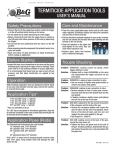
Rob Pleas Photography
GH-13 Gimbal Head
----------------------------User’s Manual
INTRODUCTION
Thank you for purchasing the GH-13 Gimbal Tripod
Head from Rob Pleas Photography. To get the most
out of your tripod head, please read this user's
manual thoroughly before use.
This user's manual explains the GH-13’s functions,
operation methods, and specifications. In addition,
keep your camera’s user’s manual handy for quick
reference.
Key Features
1.
2.
3.
4.
5.
6.
7.
8.
9.
Made in the USA
All Aluminum Construction
Ball Bearing Operation
Compact Size
Lightweight
Easily Replaced Components
Versatility
Designed by a Photographer
Supports most collared lenses (with a foot) up
to and including Nikon’s 500mm f/4 lens and
Canon’s EF 400mm f/5.6 lens.
10. Uses a low-reflective black anodized finish
similar to the finish used by the military on
many of its weapon systems.
USER NOTICE
Your GH-13 Gimbal head has been designed for
years of maintenance free use. Please follow the
guidelines below to ensure the best performance,
reliability, and durability expected from your product.
1. Do not exceed the maximum specified load
capacity (see product specification chart or visit
www.robpleasphotography.com).
2. Always ensure that the Gimbal lock-pins D and
E are engaged (i.e. locked) before mounting or
dismounting a camera lens onto the head!
3. Do not use the Gimbal head below
temperatures of -4°F or above +158°F (-20°C /
70°C).
4. Always clean and dry the Gimbal head after it
has been exposed to wet, dusty, sandy, or
salty conditions. Your GH-13 Gimbal head is
not recommended for use in salt water. Blot
the head dry and wipe clean with a soft cloth.
Remove any dust, dirt, or sand from the head,
bearings, and all moving parts!
5. Do not leave the Gimbal in the sun for
prolonged periods and avoid high temperature
exposure.
USER NOTICE - CONT’D
6. Do not use this product near electrical lines,
power lines, or in an electrical or lightning
storm.
7. Keep fingers and other body parts away from
moving or rotating components of the Gimbal
head.
8. Do not leave the Gimbal head unattended
when working where the general public could
be endangered. Keep out of the reach of
children.
9. Remove camera lens and all gear from the
GH-13 Gimbal head and any tripod or
monopod when transporting.
10. You may notice marks on the finish where the
lock-pins engage. This is normal and
expected.
SETUP
1. Ensure that lock-pins E and D are their locked
position. When locked, ‘L’ frame A and swing
bracket B will be prevented from rotating
and/or swinging.
2. Attach the center column of your tripod to lower
shaft C and hand tighten.
3. Stand behind the Gimbal head and position the
“L’ frame to your right.
4. Attach your quick-release plate to the top of
inner swing-bracket B. Position the quickrelease plate so that the lens will be pointed
away from you when attached.
5. If you do not have a quick-release plate, use
the included bolt and carefully attach your lens
to swing bracket B. Hand-tighten the bolt only.
6. With the lens securely attached to the GH-13
Gimbal, carefully attach the camera body to the
lens.
OPERATION
1. With your left hand securely holding the foot of
the camera lens, pull the handle of lock-pin D
upwards with your right finger(s) and rotate the
handle 90°. This will release the locking
mechanism of the lock-pin and allow the tripod
head to rotate.
2. While still securely holding the foot of the
camera lens, now pull the handle of upper lockpin E and rotate it 90°. Swing bracket B will
now swing freely. If the camera or lens tends
to drop, the balance may need adjustment.
Minimal adjustment is available.
3. To adjust the balance, simply loosen the quickrelease plate and slide it forward or backwards
within the slot. Also, some lenses have holes
in the feet that allow the lens to be placed in
different positions on the quick-release plate.
Note that some experimenting may be
required.
It is now highly recommended that you practice
rotating and swinging your camera to get the feel of
the tripod head and how it operates. A quick flip of
the lock-pin handles will cause them to lock the swing
bracket and ‘L’ frame as soon as the centering holes
align with the lock-pin.
ADJUSTMENT
The tension on the bearings is preset at the factory;
however, it may or may not be correct for your
specific lens. Therefore some adjustment is possible.
This is an advanced process that requires hand tools
and is not recommended due to the possibility of
damage to the GH-13 and/or your camera equipment!
If you feel you must change the bearing tension, a
simple crescent wrench and hex wrench can be used
to increase or decrease tension on the bearings.
Make your adjustments carefully and slowly. Too
much tension can damage the bearings and prevent
the swing bracket B and shaft C from moving. Too
little tension could cause the shafts to fall out of the
frame thereby causing damage to your equipment
and the tripod head. Remember that damage to
your equipment is not covered by misuse or misoperation of the GH-13 Gimbal head.
GH-13 PARTS DIAGRAM
A “L’ Frame
B Inner Swing Bracket
C Lower Shaft
D Lower Lock-Pin
E Upper Lock-Pin
F Lower Bearing Stack
G Upper Bearing Stack
SPECIFICATIONS
Weight
1 lb 10 oz..
Max. Dimensions 9 3/8”H x 1”W x 5 1/2”L
Maximum Specified Load Capacity 13 lbs
Robco, LLC. dba Rob Peas Photography
E-mail: [email protected]
Fax: (253) 537-3558
www.robpleasphotography.com
Specifications and design are subject to change without notice.
All tradenames, logos, and brand references are the respective
trademarks of their owners.