1
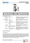
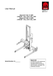
TEDDY W5A
US
OPERATING INSTRUCTIONS
EXPLODED VIEW
No ...... Description ............................................................................................................. Part No.
1 ...... Control button, l. and r. ........................................................................................... AR005-178-TZ005
2 ...... Base ......................................................................................................................... AR005-022-TZ002
2.1 ... Fuse 5 A, slow, 110V .............................................................................................. AR005-418-00001
3 ...... Cover plate .............................................................................................................. AR005-347-TZ001
4 ...... Cable with Rheostat and microswitchs.................................................................... AR005-193-TZ001
5 ...... Tilt Bearing, l. and r. ................................................................................................ AR005-337-TZ001
6 ...... Lid ........................................................................................................................... AR005-024-TZ002
7 ...... Intermediate shaft ................................................................................................... AR005-325-TZ001
8 ...... Upperpart ................................................................................................................ AR005-023-TZ002
9 ...... Lockpin ................................................................................................................... AR005-332-TZ001
10 .... Planetary Head ........................................................................................................ AR005-002-TS001
11..... Control board .......................................................................................................... AR005-378-TS001
12 .... Transformer 115V ................................................................................................... AR005-368-TZ001
13 .... Transmission and motor .......................................................................................... AR005-339-TZ001
13.1 . Poly-V belt............................................................................................................... AR005-090-TZ001
14 .... Release housing ...................................................................................................... AR005-372-TS001
15 .... Weight Compensator ............................................................................................... AR005-352-TZ001
16 .... Attachment drive ..................................................................................................... AR005-010-TZ001
17 .... Machine feet ............................................................................................................ AR005-213-TZ001
18 .... Fixing of bowl ......................................................................................................... AR005-340-TZ001
19......Power Cable..............................................................................................................AR005-194-TD006
20......Receptacle male........................................................................................................STA 7210
21......Torx Screw for Tilt Bearing......................................................................................STA 5700
22......Microswitch..............................................................................................................30E-508
23......Bolt,Top Lid..............................................................................................................AR005-344-TS001
1
US
OPERATING INSTRUCTIONS
TEDDY W5A Food Mixer
with Attachment Drive
:
TM
CONTENTS
GUARANTEE: ...................................................................................................................................................... 1
....................................................................................................................................................... 1
SAFETY:
INSTALLATION OF NEW MIXER: ................................................................................................................................ 1
CONNECTION TO POWER: ...................................................................................................................................... 2
INTRODUCTION TO THE MIXER: ................................................................................................................................ 2
RECOMMENDED WORKING SPEEDS: ......................................................................................................................... 2
OPERATION OF THE MIXER: .................................................................................................................................... 3
MAXIMUM CAPACITY OF THE MIXER: ......................................................................................................................... 3
OVERLOAD: ....................................................................................................................................................... 3
CLEANING AND HYGIENE: ...................................................................................................................................... 3
MAINTENANCE:.................................................................................................................................................... 4
LIST OF ERRORS AND POSSIBLE SOLUTIONS: ............................................................................................................. 4
MOUNTING OF ACCESSORIES: ................................................................................................................................. 4
RECOMMENDED SPEEDS FOR ATTACHMENT DRIVE: ...................................................................................................... 4
GUARANTEE:
The guarantee does not cover faults resulting from faulty operation, overloading and lacking observance of directions of
maintenance.
INSTALLATION OF NEW MIXER:
The following equipment is included:
√ Cable
In case you want further information, please state machine type
and serial number of the mixer.
√ Hook
√ Beater
√ Whip
√ Ingredient chute
In case of complaints, please contact your dealer.
√ Bowl
√ Lid for the bowl
SAFETY:
Before taking the mixer into use, check that all parts are delivered.
The safety of the user is achieved by:
Dimensions and weight:
•
The mixer will only start when the upper part is lowered.
TEDDY incl. equipment:
•
The upper part can only be tilted up when the mixer is
stopped.
•
Net weight with equipment:
44 Lbs.
•
Outside dimensions of mixer:
18¼ “ x 9½ “ x 15¾ “
•
Protection from excess current, excess voltage and too
low voltage.
•
The mixer is provided with fixed bowl screen.
The mixer is designed for manufacture
of products which do not during processing cause reactions or emit substances
which may be detrimental to the user.
Putting your fingers in the bowl while the
mixer is running may cause injuries.
The mixer is listed by:
Location:
The mixer is to be placed on a stable and horizontal table.
5489 Campus Drive.
Shreveport La 71109
800 222-1138
www.varimixer.com
[email protected]
™TEDDY is a registered trademark belonging to A/S Wodschow & Co.
042005 US
2
CONNECTION
Equipment:
TO POWER:
As standard the mixer comes with the following equipment:
The enclosed cable must be used.
The mixer must be connected to ground!
•
Only single phase power supply with ground must be used
for the mixer. Use the enclosed cable.
•
A plug with 2 pins + ground must be used.
•
Check that the voltage of the power supply corresponds
the voltage printed on the rating plate placed in the bottom of the mixer and stated on the packing.
•
The mixer must be protected by a differential circuit
breaker and a fuse of max. 15Aps0 A.
A fuse is built into the cable plug.
•
Bowl in stainless steel.
•
White plastic lid for bowl (lids in various colors are available).
•
Ingredient chute.
•
Dough hook in stainless steel for kneading of dough.
•
Beater in stainless steel for mixing.
•
Whip in stainless steel for whipping.
The power characteristics of the mixer:
Supply
voltage (V)
115
Output Frequency
(W)
(Hz)
300
Hook
Voltage
(A)
Motor Power
(HP)
3
0.4
60
INTRODUCTION TO THE MIXER:
TEDDY is a small professional mixer for kneading, mixing and
whipping in bakeries, confectioneries or kitchens.
Whip
Bowl
Beater
Lid
Ingredient chute
Extra equipment:
Any operation of the mixer is made by means of the rotary knobs
on the sides of the mixer. The two knobs can be used simultaneously or individually and are used both for speed regulation
and as opening/closing function.
The attachment hub A makes it possible to connect meat grinder
and vegetable slicer.
Meat grinder
RECOMMENDED
Vegetable slicer
WORKING SPEEDS:
•
Position 1-2:
Low speed
Kneading
•
Position 1-3:
Medium speed
Mixing
•
Position 1-5:
High speed
Whipping
Fig. 1 The construction of the mixer
A
B
C
D
E
F
G
H
I
J
Attachment hub
Housing of the planetary gear
Bowl screen in stainless steel
Bayonet shaft
Lid
Upper part
Ingredient chute
Rotary knobs (two pcs.)
Base
Bowl in stainless steel, contents 5 quarts
Fig. 2 Recommended working speeds
3
OPERATION OF THE MIXER:
US
MAXIMUM CAPACITY OF THE MIXER:
The working capacity of the mixer depends of:
The bowl must be mounted when the
mixer is started!
A.
Turn the rotary knobs to the locking symbol (fig. 3A).
•
The tool used.
•
Sort and quantity of the raw materials.
•
The optimum speed for a good result.
Too big quantities will always reduce the
quality of the product and the life of the mixer.
Overloading can also result in sudden stops.
Raw
material
Approx. max.
quantity
Bread dough, 50%
Lbs
5
Mashed potatoes
Lbs
4
Qt
1
Layer cake
Lbs
6
Cake donuts
Lbs
6
Product
A: Locking symbol B: Neutral position
C: Speeds
Fig.3 The three positions of the rotary knobs.
B.
Tilt backwards the upper part of the mixer.
C.
Place a tool in the bayonet shaft and turn it counter-clockwise to lock it in position (fig. 4).
Whipped cream
OVERLOADING:
If the mixer is moving e.g. kneading dough, this is not due to
errors or overloading.
In case of overloading the electronic variator will reduce the
current to the motor and stop it.
In case of stop due to overloading, turn
the rotary button back to neutral position,
and the mixer can be started again.
Fig. 4 Mounting of tool in the bayonet shaft.
D.
Place the bowl between the three locking bolts in the foot
of the mixer and turn it clockwise until locked (fig. 5).
If the motor stops after long time of operation, and cannot be
started immediately after, the thermosensor of the motor has
switched off the current, and the mixer needs to cool down before it can be re-started. This protects the motor from overheating.
The mixer contains two thermal cut-outs, which automatically
reconnect in case of previous disconnection by the thermosensor.
CLEANING AND HYGIENE:
After use:
•
Remove bowl and tools.
•
Wash the bowl and the tools in hot water and detergent /
degreaser / disinfectant. Rinse with pure water and dry.
Do not spray water on the mixer
Locking bolts
Tools and bowl can be cleaned in dishwasher.
Fig. 5 Place the bowl in the mixer and turn it to be fixed
in the locking bolts.
E.
Fill the ingredients in the bowl.
F.
Tilt the upper part of the mixer, including tool, down.
G.
Start the mixer by turning the rotary knobs away from the
locking symbol and past 1. To avoid splashing and dust
from flour, it is recommended to increase the speed gradually until the required speed is obtained (fig. 3C), (see
fig. 2 for recommended working speeds).
H.
Stop the mixer by turning the rotary knobs back to neutral
position (fig. 3B).
I.
The upper part of the mixer can only be tilted backwards
when the rotary knobs is turned to the locking symbol
(fig. 3A).
•
Wipe the housing of the planetary gear, the bayonet shaft
and the bowl screen. Use a damp sponge and a detergent / disinfectant. Rinse the parts with sponge and pure
water.
•
Check that the various parts have been cleaned thoroughly.
•
Do not use abrasive detergents, which could scratch the
surface.
•
Use detergents suited for use on aluminium and plastic
(polycarbonate).
4
MAINTENANCE:
MOUNTING OF ACCESSORIES:
The mixer requires no maintenance (motor and bearings for
the mechanical parts are greased for life).
The mixer is equipped with an attachment hub with variable speed,
and with the possibility of attaching the following equipment:
Safety device:
Check the function of the safety device regularly:
•
The motor must stop when the rotary knobs is in neutral
position (see fig. 3B).
•
Meat grinder , supplied with meat tray, stomper and set of
knives consisting of blade and plate 5/32”.
•
Vegetable slicer mounted with discs for shredding, grating and cube cutting.
For further information regarding accessories, please see the special sheets following the accessories.
The mixer must always be disconnected
before mounting or dismantling of the accessory.
If the safety device does not function, do
not use the mixer. Contact your dealer.
LIST OF ERRORS AND POSSIBLE SOLUTIONS:
If the problem cannot be solved, contact
your dealer.
Mounting of accessories (fig. 7):
•
Assemble the accessory in question.
•
Stop the mixer.
The mixer does not start:
•
Turn the cover plate C away from the hole.
Check that ...
•
The upper part of the mixer is in its down position.
•
When mounting the pre-mounted accessory A, the shaft
B is inserted into the attachment drive D of the mixer.
•
The mixer is plugged in and connected to power.
•
•
The electrical power supply is correct.
By turning the accessory until the pin E is pointing towards the slot G a correct clutch is obtained.
•
The fuse in the cable plug (fig.6, 1) has not been burned.
If the fuse is defective, it can be replaced by the extra
fuse (fig.6, 2) that is also available in the cable plug.
•
The accessory is pushed as far into the attachment hub D
as possible. (The pin E must be in the slot G, then the
shaft of the accessory is in a correct clutch with the attachment drive).
•
1
The accessory is fastened by turning the knob H clockwise.
Dismantling of accessories (fig. 7):
•
Stop the mixer.
•
Turn the knob H counterclockwise until the locking screw
is free of the hole F.
•
Take out the accessory of the attachment hub, dismantle
and clean it.
2
Fig. 6
Fuses in the cable plug.
The mixer stops during work:
•
The mixer is overloaded due to too high speed or too
heavy loading. See the paragraph "Overloading".
In case of power failure set the rotary
button back to neutral position, and the
mixer can be started again.
The tool is stuck in the bayonet shaft:
This is normally due to insufficient cleaning or damaged hole in
the tool:
•
When the tool is stuck, do not force it free. Apply a little
oil and let this work a couple of minutes.
•
Turn the tool backwards and forwards until it can be removed.
Unnormal noise:
Metallic noise ...
•
The tool is distorted and hits the bowl.
•
The bowl has been damaged or is not in its proper position.
Fig. 7 Mounting of accessories.
RECOMMENDED SPEEDS FOR ATTACHMENT HUB: