1
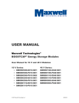
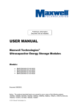
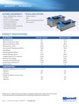
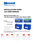
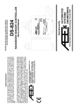
USER MANUAL
Maxwell Technologies®
Ultracapacitor Energy Storage Modules
Models:
16 V Series:
BMOD0500 P016 B01
BMOD0500 P016 B02
BMOD0250 P016 B01
BMOD0110 P016 B01
48 V Series:
BMOD0165 P048 B01
BMOD0110 P048 B01
BMOD0083 P048 B01
BMOD0165 P048 B06
Document 1008491
Notice: The products described herein are covered by one or more of the following patents:
7307830, 7203056, 7027290, 7352558, 7295423, 7090946, 7508651, 7492571, 7342770, 6643119,
7384433, 7147674, 7317609, 7495349, 7102877
© 2007-2011 Maxwell Technologies, Inc.
1. Introduction
The 16 V and 48 V series energy storage modules are self-contained energy storage devices
comprised of either six or eighteen individual ultracapacitor cells, respectively. The modules
include bus bar connections and integrated cell balance voltage management circuitry. Units may
be connected in series to obtain higher operating voltages, parallel to provide additional energy
storage, or a combination of series/parallel arrangements for higher voltages and energy. Voltage
management circuits function to protect each cell from operating in a damaging overvoltage
condition.
The module packaging (except for BMOD0110 P016) is a heavy-duty aluminum extruded
enclosure. The enclosure is a sealed, water-resistant device (per IEC 529 – IP65). The package
for the BMOD0110 P016 consists of a plastic housing with a metallic cover for thermal transfer.
The voltage management electronics have a single open collector logic output (except for models
with “B02” suffix) which indicates if any cell within the module is experiencing an over voltage
condition. Each module contains one temperature monitor output in the form of an NTC
thermistor.
For models with a B01 or B06 suffix, please refer to document number 1011130 for details. B01
models have a nominal balance threshold of 2.8V while the B06 model has a nominal balance
threshold of 2.6V. Each of these has an alarm circuit as described in paragraph 3.2.3.
2. Unpacking and Handling
2.1 Unpacking
Inspect the shipping carton for signs of damage prior to unpacking the module. Damage to the
shipping carton or module should be reported to the carrier immediately. Remove the module from
the shipping carton and retain the shipping materials until the unit has been inspected and is
determined to be operational.
NOTE: The original shipping materials are approved for both air and ground shipment. The
module should be removed from the shipping carton by lifting it by the module body and not by
the terminal posts.
The shipping container should contain the following:
1 x Energy Storage Module, part number determined by module type
1 x Accessory Kit
If the unit is found to be defective or any parts are missing, contact your supplier. A Return
Material Authorization (RMA) number must be issued prior to returning the unit for repair or
replacement.
2.2 Handling
Maxwell ultracapacitor modules are designed to provide years of trouble-free operation. Proper
handling is required to avoid damage to module. In particular, the following handling precautions
should be observed:
User Manual – 16 V and 48 V Modules – Doc. No. 1008491.12
© 2007-2012 Maxwell Technologies, Inc.
Page 1
•
Do not stack modules once they have been removed from the shipping containers.
•
Do not drop modules.
exterior.
•
Do not step on modules.
•
Protect the PCBA cover from impact. If any damage occurs to the PCBA cover, contact
Maxwell for replacement instructions.
•
Do not use tools such as hammers to disengage mounting or terminal bolts.
damage may occur.
Internal damage may occur that will not be visible from the
Serious
3. Installation
3.1 Mechanical
Modules may be mounted and operated in any orientation. Two mounting surfaces are available
(except for BMOD0110 P016); one at the top and the other at the bottom surface. These top and
bottom plates are designed to support the module with no additional mechanical contact. See the
data sheet for available mounting locations. The BMOD0110 models may only be mounted with the
bottom side down to the mounting surface.
For best results the modules should not be mounted in locations where they are directly exposed
to the environment. In particular, areas of direct splash should always be avoided. In systems
that operate at voltages in excess of 60 V, appropriate protection and sealing should be used on
both module terminals to avoid shock hazards and corrosion.
A proper installation should not exert any bending or twisting torque to the module enclosure.
Ensure that the module’s mounting points are co-planar within ±1 mm. If the actual mounting
location is out-of-plane, use spacers to bring all four mounting locations within plane to within
±1mm.
Modules (except for BMOD0110 P016) have been qualified to SAE J2380 for vibration performance.
Ensure that this is adequate for the end-use environment. If more severe vibration performance is
required, consider the use of isolators to provide damping. Contact Maxwell Application
Engineering for assistance in these cases.
Each module is provided with an M5 threaded vent hole on the front panel. The module is shipped
from the factory with a screw in this hole and the use of the hole as a vent is optional. The
module is completely sealed, but if the application requires remote venting, an M5 threaded hose
barb is provided in the accessory kit. Remove the screw which is in the hole when the module is
received and replace it with the hose barb from that kit. Attach a 5/32 (4 mm) ID hose, preferably
Teflon or polypropylene, to the hose barb and route the hose to a safe venting location. In the
event of cell venting the cell may release gas which will build pressure in the module. That
pressure can be relieved through the vent tube.
User Manual – 16 V and 48 V Modules – Doc. No. 1008491.12
© 2007-2012 Maxwell Technologies, Inc.
Page 2
3.2
Electrical
WARNING
CAUTION
To avoid arcing the energy storage module should be in a
discharged state and the system power disconnected during
installation. The module is shipped discharged and with a shorting
wire. The shorting wire should be removed prior to electrical
connections.
WARNING
CAUTION
To provide the lowest possible ESR the energy storage modules are
not fused. Care should be taken within the application to prevent
excessive current flow as required. Excessive current and/or duty
cycle will result in overheating the module which will cause
irreparable damage. Please consult the specific data sheet for each
module for current and duty cycle capabilities.
NOTE: The chassis of the module should be connected to system ground through any of the
mounting holes with large enough gauge wire to carry the worst-case fault current.
The anodized coating on the ground connection surface should be removed to ensure proper
electrical contact.
3.2.1
Output Terminal Posts
The output terminals of the module consist of internally threaded aluminum posts. They are
designed to connect directly to a ring lug or a bus bar. Maximum thread depth is 16 mm.
Maxwell-supplied bolts are also 16 mm in length. If ring terminals and lock washers in excess of 6
mm are to be used, a longer bolt must be selected. In no instance should the total amount of
thread engagement be less than 10 or greater than 16 mm.
The terminal contact surface should be cleaned with a light abrasive such as Scotch-BriteTM to
remove any oxidation. Apply a layer of high conductivity anti-oxidant joint compound between the
mating surfaces (IDEAL Noalox® Anti-Oxidant Compound or equivalent). The positive terminal is
threaded for M8 x 1.25 steel bolts. The negative terminal is threaded for M10 x 1.5 steel bolts.
Lock washers are required for long term, reliable connections. Star washers are the most effective
lock washers, and split washers are not recommended. In no case should flat washers be used in
User Manual – 16 V and 48 V Modules – Doc. No. 1008491.12
© 2007-2012 Maxwell Technologies, Inc.
Page 3
addition to lock washers. For additional performance, a thread locking compound such as Loctite®
425 may be used. However, care should be taken that the thread locking compound does not
come in contact with the electrical mating surfaces.
When tightening the terminal bolts, a torque of 20 N-m / 14.8 ft-lbs for the M8 and 30 N-m / 22.1
ft-lbs for the M10 bolts should be used. Do not exceed recommended torque.
As in any electrical system, proper cable dress is required for trouble-free operation. The cables
used for attachment are large, and improperly constrained cables can place bending stress on the
terminals and terminal bolts. Cables should be installed so that they do not exert bending or
twisting torque on the power terminals, and should be routed away from the module so that they
are parallel to the top surface of the terminal and constrained within 50 cm of the terminal before
bending the cable in any direction.
High vibration environments may require additional
constraints.
Attachment to the output terminals should be made with ring lugs or bus bars of an appropriate
size for the application current. If bus bars are used, brackets should be installed to interconnect
the tops of adjacent modules to prevent undesirable lateral forces on the terminals.
The energy storage modules have low ESR. As a result, the resistance of the wires connecting the
energy storage module to the application can easily exceed the ESR of the module. Connection of
modules in series or parallel should utilize the same gauge wire (or equivalent bus bar) as
determined for final output connections. When connecting in series connect the positive output
terminal of one module to the negative output terminal of the next module. Two possible
orientations are illustrated in Figure 1.
Figure 1: Possible series connection arrangements
User Manual – 16 V and 48 V Modules – Doc. No. 1008491.12
© 2007-2012 Maxwell Technologies, Inc.
Page 4
Electrical isolation of the module is tested to 2500 VDC for a maximum allowable operating voltage
of 750 VDC. Full UL810a compliance is satisfied for up to three (3) BMOD0165 P048 modules in
series or nine (9) BMOD0500 P016 modules in series (maximum operating voltage of 150V).
When several modules are connected in series for operating at higher voltage, care must be taken
to ensure proper creepage and clearance distances in compliance with national safety standards
for electrical equipment.
3.2.2
Module to Module Connections
The 16V and 48V modules are equipped with the active voltage management circuit that protects
and monitors every cell within the module. Module-to-module balancing is not required.
Figure 2 – Series Connection of 48V Modules
Figure 4 – Series Connection of 16V Modules
Figure 3 – Parallel Connection of 48V Modules
Figure 5 – Parallel Connection of 16V Modules
NOTE: Although not depicted, modules BMOD0110 will follow similar connection schemes.
User Manual – 16 V and 48 V Modules – Doc. No. 1008491.12
© 2007-2012 Maxwell Technologies, Inc.
Page 5
3.2.3
Logic outputs
A single open collector logic output is available for overvoltage monitoring. This output will indicate
if any cell in the module has gone into an overvoltage condition. In addition, the output of the
NTC thermistor is also available for module temperature monitoring. The overvoltage signal and
temperature signal are available via the connector supplied with the module. Note: The passive
version (suffix “B02”) of the BMOD0500 only provides the output of the NTC thermistor for the
temperature monitor signal. There is no voltage monitoring signal in this module.
The logic outputs are isolated from the capacitor voltages and from chassis ground. The logic
outputs may be operated individually or wire-or’d to provide a single fault line. A table indicating
the pin out, indication and maximum current is provided below.
Pin
#
1
2
Wire
Color
Black
White
3
4
Red
Green
Pin out
designation
GRND
Overvoltage
Alarm
Not used
TEMP
Output
(16 V)
Output
(48 V)
Maximum
current
High – Inactive
Low - Active
N/A
High – Inactive
Low - Active
N/A
5 mA
N/A
NOTES:
1. Pin #2 is not used for the BMOD0500 P016 B02 model with passive balancing.
2. The Overvoltage Alarm will be asserted if any individual cell goes into an over voltage
condition. The range of the alarm threshold is as follows:
2.73V minimum
2.80V nominal
2.86V maximum
3. The Overvoltage Alarm Signal (Pin 2) is an open collector output indicating when the voltage
management electronics are active. In order to use the signal, the user must connect a pull-up
resistor (≥1kΩ) between Pin 2 and a nominal 5V (maximum 5.5V) supply.
In this
configuration, the voltage at Pin 2 will be ~ 5V when the circuit is not active. When a cell in the
module goes into an overvoltage condition, the output of Pin 2 goes low. The Overvoltage
Alarm can be used as a signal to the system electronics to stop charging in order to protect
cells from damage. When an acceptable cell voltage is reached, the output goes high again
and can be used as a signal to resume charging. Figure 6 shows a typical connection to use
this system.
4. The Overvoltage Alarm circuit can sink up to 5 mA with a VOL of no more than 0.4V. The
leakage current when the output is off is 50 nA. The proper value of the pull-up resistor
should be calculated based upon overall system circuit design.
User Manual – 16 V and 48 V Modules – Doc. No. 1008491.12
© 2007-2012 Maxwell Technologies, Inc.
Page 6
Fig. 6 – Typical connection to the monitor cable. (Users to verify values based on their circuit design)
The temperature output operates at any module voltage including zero volts.
The TEMP output is via a NTC thermistor and can be measured between pin 4 and pin 1 (GND) of
the connector. The resistance of the thermistor varies with temperature to provide the actual
temperature of the module. The thermistor is located in the center of the module. Under normal
operating conditions the temperature output should represent the module’s hottest location. The
resistance measured through the thermistor relates to temperature according to a US Sensor
thermistor with a nominal value of 10KΩ @ 25ºC (reference temperature chart for the 103JM1A.)
http://www.ussensor.com/rt charts/103JM1A.htm
A mating connector for these signals is provided with 6” (15 cm) of cable length. Additional 22
gauge wire may be spliced for longer wire length up to 6 feet (1.8 m). For lengths longer than 6
feet (1.8 m) shielded 4 conductor wire is recommended.
3.3 Thermal Performance
Low internal resistance of the energy storage modules enables low heat generation within the
modules during use. As with any electronic component, the cooler the part operates the longer
the service life. In most applications natural air convection should provide adequate cooling. In
severe applications requiring maximum service life, forced airflow or a liquid-cooled cold plate may
be required.
The thermal resistance, Rth, of the units has been experimentally determined assuming free
convection at ambient temperature (~ 25oC). The RTH value provided on the datasheet is useful
for determining the operating limits for the units. Using the Rth value a module temperature rise
can be determined based upon any current and duty cycle. The temperature rise can be
expressed by the following equation.
∆T = I 2 RESR RTH d f
where:
I = RMS current (amps)
RESR = equivalent series resistance, RDC (ohms)
RTH = thermal resistance (oC/W)
df = duty cycle fraction
The ∆T value calculated above plus ambient temperature should remain below the specified
maximum operating temperature for the module (please refer to the module datasheet) as
measured by the thermistor output. If active cooling methods are employed, it is possible to
operate at higher currents or duty cycles than if only passive cooling is utilized.
User Manual – 16 V and 48 V Modules – Doc. No. 1008491.12
© 2007-2012 Maxwell Technologies, Inc.
Page 7
4. Accessories
The following accessories are provided with modules within the accessory kit.
1
1
1
1
1
x Users Manual
Deutsch 4 pin connector. Used for Overvoltage output and temperature monitoring
x Hex head cap, M10x16, Zinc plated screw
x Hex head cap, M8x16, Zinc plated screw
x SRTG6 – Misumi, Barbed coupler. Optional item providing venting capability.
5. Operation
The module should only be operated within specified voltage and temperature ratings. Determine
whether current limiting is necessary based on the current ratings of attached components.
Observe polarity indicated on module. Do not reverse polarity.
6. Safety
WARNING
DANGER – HIGH VOLTAGE HAZARD!
Never touch the power terminals as the module can be charged and
cause fatal electrical shocks. Always check that the module is fully
discharged before manipulating the module. Please refer to the step by
step instructions below for the manual discharge procedure.
•
•
•
•
•
•
Do not operate unit above the specified voltage.
Do not operate unit above the specified temperature rating.
Do not touch terminals with conductors while charged. Serious burns,
shock, or material fusing may occur.
Protect surrounding electrical components from incidental contact.
Provide sufficient electrical isolation when working above 50 V DC.
Prior to installation on or removal from the system, it is mandatory to
fully discharge the module to guarantee the safety of the personnel.
User Manual – 16 V and 48 V Modules – Doc. No. 1008491.12
© 2007-2012 Maxwell Technologies, Inc.
Page 8
WARNING
A fully discharged module may “bounce back” if it is stored without a
shorting wire connected to the + and – terminals. This bounce back can
be as much as 6V for the 48V module and is enough to cause
dangerous electrical shocks.
6.1
Discharge Procedure
Proceed as follows to discharge the module:
1.
Using a voltmeter, measure the voltage between the 2 terminals.
2.
If the voltage is above 2V, a resistor pack (not supplied with the module) will need to be
connected between the terminals. Proper care needs to be taken in the design and
construction of such a dissipative pack. e.g. At 48V, for a 4 Ohm pack, the module will be
discharged with a peak current of 12 A and will take about 30 minutes to reach a safe
voltage. However, in this case, the peak heat/power dissipated in the resistor pack will be
~ 600 W. The resistor pack will need to be sized and provided with suitable cooling to
handle this power dissipation. Additionally, proper enclosure or other packaging is
necessary to ensure safety. In all cases, proper design of the dissipative resistor pack is
necessary.
3.
If the voltage is under 2V, connect the shorting wire provided by Maxwell to the + and –
connectors.
4.
The module is now safe for handling. However, leave the shorting wire connected at all
times until the module is installed in the system and the power cables are connected.
7. Maintenance
Prior to removal from the system, cable removal, or any other handling ensure that the energy
storage module is completely discharged in a safe manner. The stored energy and the voltage
levels may be lethal if mishandling occurs. Maintenance should only be conducted by trained
personnel on discharged modules (see above).
7.1
Routine Maintenance
7.1.1 Clean exterior surface of dirt/grime
7.1.1.1 Reason - Improve power dissipation performance.
7.1.1.2 Use a cleaning cloth dampened with a water/soap solution. Do not use high-pressure
sprays or immersion. Keep excess amounts of water away from the PCBA cover and
power terminals.
7.1.1.3 Frequency
7.1.1.3.1 Outside use (6 months, or as needed)
7.1.1.3.2 Inside use (annually)
User Manual – 16 V and 48 V Modules – Doc. No. 1008491.12
© 2007-2012 Maxwell Technologies, Inc.
Page 9
7.1.2 Check mounting fasteners for proper torque
7.1.2.1 Reason - Avoid mechanical damage
7.1.2.2 Frequency
7.1.2.2.1 High Vibration Environments (6 months)
7.1.2.2.2 Low Vibration Environments (12 months)
7.1.3 Inspect housing for signs of damage
7.1.3.1 Reason – allows potential internal damage to be identified
7.1.3.2 Frequency
7.1.3.2.1 Outside use (6 months, or as needed)
7.1.3.2.2 Inside use (annually)
7.1.4 Check signal/ground connections
7.1.4.1 Reason – avoid false signals or shock hazards
7.1.4.2 Frequency
7.1.4.2.1 High Vibration Environments (6 months)
7.1.4.2.2 Low Vibration Environments (12 months)
8. Storage
The discharged module can be stored in the original package in a dry place. Discharge a used
module prior to stock or shipment. A shorting wire across the terminals is strongly recommended
to maintain a short circuit after having discharged the module.
9. Disposal
Do not dispose of module in trash. Dispose of according to local regulations.
10. Specifications
Refer to datasheets at our website, www.maxwell.com, for specifications for each specific product.
User Manual – 16 V and 48 V Modules – Doc. No. 1008491.12
© 2007-2012 Maxwell Technologies, Inc.
Page 10
Maxwell Technologies, Inc.
Worldwide Headquarters
5271 Viewridge Court, #100
San Diego, CA 92123
USA
Phone: +1 858 503 3300
Fax: +1 858 503 3301
Maxwell Technologies SA
CH-1728 Rossens
Switzerland
Phone: +41 (0)26 411 85 00
Fax: +41 (0)26 411 85 05
Maxwell Technologies GmbH
Brucker Strasse 21
D-82205 Gilching
Germany
Phone: +49 (0)8105 24 16 10
Fax: +49 (0)8105 24 16 19
[email protected] – www.maxwell.com
Maxwell Technologies, Inc.
Shanghai Representative Office
Unit A2,B,C 12th Floor, Huarun Times Square
500 Zhangyang Road, Pudong New Area,
Shanghai 200122, P.R. China
Tel: +86 (0)21 3852 4016
Fax: +86 (0)21 3852 4099