1
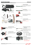
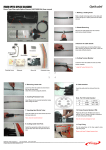
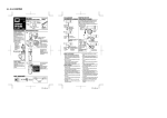
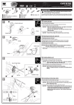
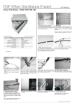
VSOF-BS403A Splice Closure for Fiber Optic Cable User Manual Rev.3 VSOF-BS403A User Manual Rev.3 1. Introduction 1.1 General VISSEM’S BS403A protects fiber optic splicing point in various installation conditions such as aerial, manholes, ducts, wall and direct buried applications. It is specially designed for FTTH network and applicable to multi branching installation by using mid-plate which is for increasing core capacity and complying with the requirements in each point of network. The flat type gasket ensures reliable sealing performance by preventing air and water leak and the corn type sealing socket provides easy and reliable installation. This closure has high mechanical strength against any environmental conditions. With VISSEM’S BS403A, you can improve your network system to the higher level. 1.2 Specifications 403A-SS 403A-SD 403A-DD Size (mm) L×W×H 435 x 205 x 113 435 x 205 x 167 435 x 205 x 221 Weight (kg) 2.8 3.8 4.8 Main Entry Ports 4 Ports/Closure 8 Ports/Closure 12 Ports/Closure Cable Dia.(mm) 6 ~ 20 6 ~ 20 6 ~ 20 No. of Splice Tray 4 6 8 Tray Capacity 24F (up to 48F) 24F (up to 48F) 24F (up to 48F) Splice Capacity 96F (up to 192F) 144F (up to 288F) 192F (up to 384F) Splice Method Fusion, Mechanical, Connector Splice Protector Heat Shrinkable Sleeve, Mechanical Splicer Tension Member Galvanized Steel Wire, FRP 2/16 VSOF-BS403A User Manual Rev.3 1.3. Configuration A B C G E H D J I M F K L N O P Q R Items Descriptions Unit Q’ty Remarks A Upper Main Body EA 1 B Lower Main Body EA 1 C Splice Tray EA 1 Standard D Unit Protection Tube EA 4 Standard E Cable Tie EA Num. of Splice Trays × 4 F High Vacuum Grease EA 1 G Splice Tray Band EA 1 H Sheath Holder SET 4 Note 1 I Sheath Gasket SET 4 Note 2 J Main Body Screws EA 12 K Sheath Holder Adapter EA No. of Mono-Branch Type Note 3 Sheath Holder × 3 L T/M Ass’y SET 1 M Silica Gel EA 1 N Splice Protection Sleeve EA - O Main Body Gasket EA 1 P Grounding Wire EA 4 Optional Q Aerial Hanger EA 2 Optional R Manhole Hanger EA 2 Optional 3/16 Optional VSOF-BS403A User Manual Rev.3 (* ) Mid Plate Set (SD-Type, DD-Type) A E C D B F H G I J K Items Descriptions Unit Q’ty Remarks A Mid Plate EA 1 B Splice Tray EA 1 C Sheath Holder SET 4 Note 1 D Sheath Gasket SET 4 Note 2 E Grounding Connector EA 1 Optional F Sheath Holder Adapter EA No. of Mono-Branch Type Note 3 Sheath Holder × 3 G T/M Middle Ass’y SET 1 H Splice Tray Band EA 1 I Grounding Wire EA 4 J Mid Plate Gasket EA 1 K Main Body Screw EA 12 Optional Note 1. The type of sheath holder shall be accordance with type of sheath gasket. (mono, di, tetra or octa-branch type) Note 2. The type of sheath gasket shall be accordance with customer’s requirements. Note 3. Do NOT provide for di, tetra and octa-branch type sheath gasket. 4/16 VSOF-BS403A User Manual Rev.3 2. Direction 2.1. Getting Started 2.1.1. Confirm the cable structure and the fiber type before starting the work. Different types of fibers cannot be spliced together. 2.1.2. Seal the splicing part perfectly to minimize cable damages by moisture. Do not apply any impact to the splicing part. 2.1.3. Keep the working place free from moisture or dust. Do not give any impact on the cables. Do not bend or twist cables. 2.1.4. During the sheath stripping and the closure assembly procedures, use permitted tools according to an approved fiber optic splicing standard in your region. 2.2. Cable Preparation 2.2.1. Secure the cables firmly on the working table. 2.2.2. Cut off about 1m from the cable end including the pulling eye. 2.2.3. Clean the cut area with clean cloth. 2.3. Marking a Cutting Point 2.3.1. Mark a sheath removing point on the cable with a piece of tape at a 150cm point from the cable cut end. (Figure-1) [Figure-1] 2.3.2. In case of mid-span branching with mark a sheath removing point on the cable with a piece of tape at a 300cm point from the cable cut end. 5/16 VSOF-BS403A User Manual Rev.3 2.4. Sheath Removing 2.4.1. Remove the cable sheath from the marked point by using a sheath stripper. (Figure-2) Note. Be sure not to damage the fiber optics. 2.4.2. Remove all plastic tape and dummy filler tubes. (Figure-3) 2.4.3. After trimming off dummy filler tubes, clean the loose tubes by using jelly cleaner. [Figure-2] [Figure-3] 2.5. Cutting Tension Member (T/M) 2.5.1. Leave 14cm from the cable and cut off the tension member. (Figure-4) Note. Be careful not to cut loose tubes. 2.5.2. Remove PE coatings from the tension member if required. [Figure-4] 2.6. Removing Loose Tubes 2.6.1. Leave about 4cm from the cable sheath end and remove the rest of the loose tube. (Figure-5) 2.6.2. Clean the cut area by using jelly cleaner. Note. Be sure not to damage the fiber optics. [Figure-5] 6/16 VSOF-BS403A User Manual Rev.3 2.7. Inserting Unit Protection Tube 2.7.1. Insert fibers into the unit protection tubes carefully all the way up to the point where loose tubes end. (Figure-6) 2.7.2. Wrap the tape around the end point of protection tube at cable side. (Figure-7) Note1. Be careful not to damage inner fibers. Note2. The unit protection tube is provided in different colors for unit identification. The colors are blue, orange, green. Unit Protection Tube tion Tube [Figure-6] [Figure-7] 2.8. Cutting Sheath Gasket 2.8.1. Check the outer diameter of the cable and cut off the sheath gasket according to the cable diameter marked on it. (Figure-8, Figure-9, Figure-10, Figure-11) Mono-Branch Type D C B Cutting Point Cable Diameter A 6mm B 8 ~ 10mm C 12 ~ 14mm D 16 ~ 20mm A [Figure-8] Di-Branch Type A (Inside) [Figure-9] 7/16 Cutting Point Cable Diameter A 11 ~ 12mm VSOF-BS403A User Manual Rev.3 Tetra-Branch Type B Cutting Point Cable Diameter A 6 ~ 8mm B 10 ~ 12mm A [Figure-10] Octa-Branch Type Cutting Point Cable Diameter A 3mm, 5~6mm A (Inside) [Figure-11] 2.8.2. In case of mid-span branching with mono-branch type sheath gasket, cut off one side of sheath gasket, or by using equivalent. (Figure-12, Figure-13) [Figure-12] [Figure-13] 2.9. Applying High Vacuum Grease 2.9.1. Apply the high vacuum grease on the cable end to prevent the cable sheath from scratch and make it easy for sheath gasket insertion. (Figure-14) [Figure-14] 8/16 VSOF-BS403A User Manual Rev.3 2.9.2. In case of mid-span branching with mono-branch type sheath gasket, apply the high vacuum grease on the cutting surface of sheath gasket. (Figure-15) [Figure-15] 2.10. Inserting Sheath Gasket 2.10.1. Pass the unit protection tubes through the sheath gasket to the cable cut end. (Figure-16) 2.10.2. In case of mid-span branching with mono-branch type sheath gasket, insert cable into sheath gasket and fasten sheath gasket to the cable by using cable tie. (Figure-17) [Figure-16] [Figure-17 2.11. Assembling Sheath Holder Adapter 2.11.1. Put the required number of sheath holder adapters on the lower groove of the sheath holder according to the cable diameter. (Figure-18 Figure-19) Sheath Holder Sheath Holder Adapter [Figure-18] [Figure-19] 9/16 VSOF-BS403A User Manual Rev.3 2.11.2. Insert the lower part of the sheath holder into the inlet of the closure. (Figure-20) [Figure-20] 2.12. Fixing Cable Sheath 2.12.1 Put the optical cable with sheath gasket on the entry of the closure and close it with upper sheath holder. (Figure-21) 2.12.2. Fix the cable sheath by using a screwdriver. (Figure-22) [Figure-21] [Figure-22] 2.13. Fixing Tension Member 2.13.1 Lift up the splice tray and place the T/M (tension member) on the T/M supporter. (Figure-23) 2.13.2 Put the T/M supporter cover on the T/M and tighten them together by using a screwdriver. (Figure-24) [Figure-23] [Figure-24] 10/16 VSOF-BS403A User Manual Rev.3 2.14. Drop Cable Guiding (if required) 2.14.1. In case of using octa-branch type sheath gasket, for guiding insert the drop cable from lower side into the drop cable guider by turns. (Figure-25) [Figure-25] 2.15. LAP Grounding (if required) 2.15.1. Cut the cable sheath about 1cm from the cut end. (Figure-26) 2.15.2. Connect the grounding wire tab to the sheath and clamp tightly. (Figure-27) [Figure-26] [Figure-27] 2.16. Arranging Unit Protection Tubes 2.16.1. Arrange the unit protection tubes considering the bending radius. (Figure-28) 2.16.2. Insert the unit protection tube into the inlet on the splice tray and fix the unit protection tubes by using cable ties. (Figure-29) 2.16.3. In case of mid-span branching with lift up the splice tray and arrange the surplus loose tube Note. Be careful not to damage the inner fibers [Figure-28] [Figure-29] 11/16 VSOF-BS403A User Manual Rev.3 2.17. Splicing and Storing Fibers 2.17.1. Preparation 2.17.1.1. Clean the working desk and check the fibers carefully. 2.17.1.2. Cut each fiber end carefully to make a perpendicular cut to the fiber axis. 2.17.2. Splicing 2.17.2.1. Splice fibers in accordance with splicing method to be approved. Note1. Be careful not to twist or bend fibers. Note2. There should be no damage or flaw on the cut area and keep the fibers from dust to minimize the data loss. Note3. Single mode fibers should be spliced together carefully to maintain a constant center axis. Note4. If there is any problems with the splice, then cut the splicing point and splice them again. 2.17.3. Arranging the splices 2.17.3.1. After the splice, insert the splice protection sleeve in each slit accordingly. (Figure-30) 2.17.3.2. Coil surplus fibers in the tray in a figure 8 shape. 2.17.3.3. After the arrangement, apply the O-ring into the slit and close the tray lid. 2.17.4. Record each splice on the index card on the lid. (Figure-31) [Figure-30] [Figure-31] 2.18. Stacking Splice Trays 2.18.1. Place the tray cover on the tray properly and stack the trays by using the connection parts on the side. 2.18.2. Repeat the splicing procedure. (Figure-32, Figure-33) [Figure-32] [Figure-33] 12/16 VSOF-BS403A User Manual Rev.3 2.18.3. Tie the splice trays by using splice tray band to be provided. (Figure-34) [Figure-34] 2.18.4. Place the silica gel to be provided around the splice trays. 2.19. Putting Gasket 2.19.1. Apply the high vacuum grease on the part of sheath gasket only after cleaning. 2.19.2. Put the main body gasket on the groove. (Figure-35) [Figure-35] 2.20. Assembling the Mid Plate (if required) 2.20.1. Assembling the mid plate in accordance with Procedure 2.1 ~ 2.17 above mentioned. [Figure-36] [Figure-37] 13/16 VSOF-BS403A User Manual Rev.3 [Figure-38] [Figure-39] Note. Connect T/M middle ass’y to T/M ass’y by using grounding connector. 2.21. Assembling the Closure 2.21.1. Place the upper main body to the lower one properly. (Figure-40) 2.21.2. When using the mid plate, place it on to the lower main body and cover the upper one. (Figure-41) [Figure-40] [Figure-41] 2.22.3. Tighten the closure body with the provided screws listed below. (Figure-42) [Figure-42] 14/16 VSOF-BS403A User Manual Rev.3 2.22. Mounting the Closure 2.22.1. Manhole Mounting 2.23.1.1. Connect two hangers to the body with bolts and nuts. (Figure-43) 2.23.1.2. Hang the closure on the hanger bar properly by using manhole hangers. (Figure-44) 2.23.1.3. In case of using mid-plate, connect two aerial hangers to both right and left side of the body. [Figure-43] [Figure-44] 2.22.2. Aerial Mounting 2.22.2.1. Connect two hangers to the body with bolts and nuts. (Figure-45) 2.22.2.2. Hang the closure on the wire properly by using aerial hangers. (Figure-46) 2.22.2.3. In case of using mid-plate, connect two aerial hangers to both right and left side of the body. [Figure-45] [Figure-46] 2.22.3.Wall Mounting 2.22.3.1. Connect two hangers to the body with bolts and nuts. (Figure-47) 2.22.3.2. Hang the closure on the hanger bracket properly by using wall mount bracket. (Figure-48) [Figure-47] [Figure-48] 15/16 VSOF-BS403A User Manual Rev.3 2.23. External Grounding 2.23.1. Connect the external bonding wire to the ground terminal on the closure and connect the opposite end of bonding wire to a designated terminal. (Figure-49) [Figure-49] The BS403A has been made under strict quality control and tests. Our products passed several inspection criteria, specifications and other certification standards. The technical facts of the products are based upon reliable information, but the user should consider the usage and applicability of the product before operation. Sellers do not assume any liability resulting from improper use. The contents of this manual are made in lieu of all warranties, but sellers do not take the responsibility for any damage caused by users or any statements unrelated to this manual. VISSEM Electronics 235-2, Deokpyeong-ri, Majang-myeon, Icheon-city, Gyeonggi-do, Korea 467-812 www.opticube.co.kr Tel: 82-31-283-7852 Email: [email protected] Fax: 82-31-283-7844 VISSEM OPT-M0711 Printed in Korea 16/16