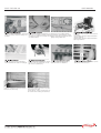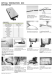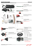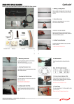
1
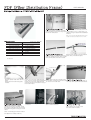
USER MANUAL
Place two plastic washers on each Mount Swing-out Modules(SJOF-FD
side and attach the grounding termi F-RM-48C) on a 21" open rack or a
cabinet using an approved installation
nal on the real panel
method.
Note: You can move the Mounting tabs to the
middle to mount the module on a 19" rack.
SJOF-FDF-RM-48C
ITEM
Steel band
Protection tube(OSP)
Protection tube(Cord)
Splice Tray (STI 24-6)
Cable tie
Ground Terminal set(*)
User manual
QTY
2 each
2 each (1000mm)
5 each(25mm)
1 each per 24 cores
12 each
4 each
1 each
Sheath removing
Remove the sheath from the marked
Cut off about 1m from the end and point using a sheath stripper.
mark the stripping point using a tape
at a 150cm point from the cut end.
(*) optional
Protection tube
Steel band
Tension member
Remove plastic tape and dummy
fillers.
Clean the loose tube using jelly
cleaner.
Leave 7cm from the Cable Sheath
Insert fibers into the colored Proteend and cut off the Tension Member.ction tubes. Push the protection tubeSecure the cable to the rear side of
Leave 5cm from the Cable Sheath
the shelf with a provided steel band.
up to the loose tube end.
end and remove loose tubes using a
loose tube cutter.
Ground terminal
Connect Grounding wire to Ground Connect on the side of Grounding
Terminal
wire to Rack earth bar
If the OSP cable has a metallic
sheath and tension member, insert
Fixed splice (STI 24-6) to the
the tension member into the ground
rear door with bolt (M3)
terminal and tighten it using a screw
driver.
Note : Grounding procedure cannot
be skipped for safety reasons
USER MANUAL
VSOF-FDF-RM-48
After the cable termination, protection Insert each 6pigtail cords(each 0.9 Place the loose tubes(25mm)
tubes are routed into the swing-out mm) into a provided 25mm protecti containing optical fibers on the
on tubes to make a cord unit for easplice tray inlet, and fasten them
module.
tightly using cable ties.
sy identification.
After record the contents of works Connect patchcords on the
When the splicing is completed,
insert sleeves into slits accordingly. on the cover of splice tray, close opposite side of adapters.
the cover of splice tray.
After the completion, push the module
back into the main body.
Record the splicing list on the card attached on the front door.
Check splicing, routing, storage and system status before starting the operation.
Check the color of fibers and remove
coatings.
Cut the fiber using an approved fiber
cutting method.
Splice fibers using an approved fiber
splicing method.
Pull out the patch cords toward the system
through the reserved holes.