1
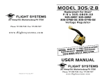
MODEL 826
FLIGHT SYSTEMS
Replacement For Onan®
P/N 305-0826
Voltage Regulator
505 Fishing Creek Road • Lewisberry, PA 17339
Phone: 717-932-9900 • Fax: 717-932-9925
www.flightsystems.com
ON
NSTALLATI
I
E
R
P
“
5
.
EAD PG
NSTALLING
I
NOTICE: R
E
R
O
F
E
B
CE”
OR
MAINTENAN
6 REGULAT
2
8
L
E
D
O
M
YOUR
USER MANUAL
Installation - Operation
FLIGHT SYSTEMS
Printed in USA - Revised Nov. 2006
505 Fishing Creek Road • Lewisberry, PA 17339
Phone: 717-932-9900 • Fax: 717-932-9925
www.flightsystems.com
FLIGHT SYSTEMS
MODEL 826 Manual
FLIGHT SYSTEMS
MODEL 826 Manual
OTHER PRODUCTS & SERVICES
TABLE OF CONTENTS
• Model 826 Features ...................................... 1
• Mounting Diagram ...................................... 2
• Description .................................................. 3
• Pre-Installation Maintenance ........................ 5
• Specifications ............................................... 6
• Footprint Diagram ...................................... 7
• Plug Pin Diagram ........................................ 7
• Warranty Information .................................. 8
• Other Products & Services ........................... 9
NEW UNITS - Flight Systems sells Improved Replacements for these
Onan® Controls, some of which are no longer offered by the Mfg:
OEM Part #
Description
®
ONAN 300-C859
GEN SET CONTROL
ENGINE CONT. MNTR.
ONAN® 300-0679/80
ONAN® 300-0681/82
ENGINE CONT. MNTR.
ONAN® 300-B1073, B944
RV GEN SET CONTROL
ONAN® 300-1006/1404/1540
YD REGULATOR
ONAN® 300-2604, 2605
ENGINE MONITOR
ONAN® 300-2784, 2943
RV GEN SET CONTROL
ONAN® 300-3056, 3687, 3950
RV GEN SET CONTROL
ONAN® 300-3763, 5268
RV GEN SET CONTROL
ONAN® 300-3764, 5342
RV GEN SET CONTROL
®
ONAN 305-0809-01,-0851, -0782
RV GEN SET REGULATOR
ONAN® 305-0911
COMMERCIAL GEN SET VR
ONAN® 332-1268
VR21 REGULATOR
®
VR21 REGULATOR
ONAN 332-1956
If you service ONAN® RV GEN SETS you need
to meet the “G-MAN”! - Is the problem with the control
board, the regulator, the windings or other components? The
G-MAN can tell you, saving hours of tedious guesswork!
Available adapters allow testing of dozens of Emerald, Marquis, Microlite & Camp Power models.
The SLICK STICK Keeps your gen set properly maintained -- cleans and refinishes slip rings quickly and safely!
REBUILDING SERVICE - Flight Systems rebuilds over 200 different
Onan®, Kohler®, Generac®, Basler®, ASCO® and other Generator & ATS
Controls. Please call or see our website for a complete list.
ENGINE/GENERATOR PROTECTION/CONTROLS - We
offer a variety of rugged products which provide Engine Protection That Works!
Our Model 540 offers control and protection for fully automatic gen sets and
other standby engines. The ENGINE SAVER® provides the ultimate in
protection, having prevented destruction of thousands of engines throughout the
world since 1980. Contact our Marine & Industrial Controls Dept for details.
9
MODEL 826 Manual
FLIGHT SYSTEMS
MODEL 826 Manual
FLIGHT SYSTEMS
MODEL 826 FEATURES
WARRANTY INFORMATION
Note: Always Refer to the Specific Generator Set Manual
when Troubleshooting Problems.
The Model 826 Generator Voltage Regulator is warranted to be free
from defects in materials and workmanship for a period of two years
from the date it was sold. (This date appears on unit label)
Flight Systems’ Limited Warranty covers the repair or replacement
of defective product within the warranty period. It does not cover
the cost of installation, or removal costs incurred, or possible damage to other equipment (including the generator or parts thereof)
as a result of the Model 826 Generator Voltage Regulator.
Flight Systems (or its authorized agent) shall reserve the right to
determine the cause of malfunction.
In the case if we determine that it was due to abuse, misuse, improper installation, acts of nature, failure to perform recommended gen set maintenance procedure or problems elsewhere
in the gen set, the warranty claim shall be disallowed and established repair rates shall apply. Alteration of the unit in the field
will also void warranty.
Ship defective units directly to:
FLIGHT SYSTEMS
505 Fishing Creek Road
Lewisberry, PA 17339
Attention: Warranty Service
The Flight Systems Model 826 was designed as a direct replacement
for Onan P/N 305-0826. It is an exact fit and requires no modification. The Model 826 is a metal-cased regulator used in all Marquis
models (BGM and NHM series). Note: Refer to the specific Onan
service manual for your model when servicing these generators.
Flight Systems has been repairing and building replacement generator
controls for nearly 30 years. The Model 826 continues our tradition of
designing and building products which will not only perform exactly as
the original, but offer improvements in operation and longevity. See Page
9 for our other products & services.
Model 826 Regulator Features Include:
1.
2.
3.
4.
5.
6.
7.
8.
9.
10.
Rugged packaging
Weather proof cast aluminum housing
Improved resistance to summer heat
Designed for long life
Latest technology
Loads protected from under frequency
Loads protected from overvoltage on overspeed
Cost-Effective replacement
Ease of installation; cut out for socket wrench
Full Two Year Warranty
Please prepay all freight charges and note the nature of the failure, if known.
NOTICE: If preventative maintenance procedures (see
gen set owners manual and “Pre-Installation Maintenance” on pg. 5 of this manual) have not been performed
prior to installing this regulator, damage can result - such
damage is NOT covered under warranty!
8
1
MODEL 826 Manual
FLIGHT SYSTEMS
MODEL 826
MOUNTING DIAGRAM
MODEL 826 FOOTPRINT DIAGRAM
To
wa
r
d
En
gi
ne
ç
MODEL 826 Manual
FLIGHT SYSTEMS
ç
To
E
xis
tin
gP
lu
g
MOUNTING
The voltage regulator is mounted on the end of the generator housing
by means of the existing Onan bracket (305-0825-02) and two bolts.
Hold the regulator with the harness facing the front. The upper bolt
goes through the regulator and bracket into the threaded hole in the
housing. The lower bolt goes through the regulator directly into the
bracket. Cutouts in the sides of the case provide access for a socket
wrench. While mounting the regulator, it is important to route the
harness and plug under the end of the generator housing and up
through the slot in the control compartment. The black sleeve over
the harness protects it from abrasion.
2
MODEL 826
PLUG PIN
DIAGRAM
(Front View of Plug)
7
MODEL 826 Manual
FLIGHT SYSTEMS
SPECIFICATIONS
BATTERY VOLTAGE:
Voltage 12 VDC +/- 2 V.
FIELD:
Voltage Range 20-75 VDC, Nominal. Peak 160 V.
Current 6 A continuous, peak 15 A at 175º F.
Field Flash 12 VDC with 12.7 VDC battery.
FREQUENCY RANGE: 45-65 Hz, Nominal 60 Hz.
Voltage ramps down with frequency.
(See Table Below)
VOLTAGE REGULATION: 120 V +/- 2 V. No load to full load.
OPERATING TEMPERATURE RANGE: To 175º F.
ISOLATION TO CASE: Greater than 10 Meg. Case is grounded.
ENVIRONMENTAL CHARACTERISTICS: Unit has a metal
case and is intended to be mounted inside of electrical enclosure.
RELATIVE HUMIDITY: 0 - 95 percent.
VIBRATION: Vibration Resistant Package.
SIZE: See Footprint Diagram, Page 7.
MODEL 826 Manual
FLIGHT SYSTEMS
DESCRIPTION
OVERVIEW
The Model 826 regulates the voltage output of your generator. By
constantly monitoring the voltage and frequency output at the stator,
the Model 826 effectively responds with the proper corrective action,
even under the most drastic load change. To protect loads, voltage is
automatically lowered during underfrequency operation. The Model
826 is rugged, weather-proof and heat resistant.
FIELD FLASH VOLTAGE “J4-7”
When starting the generator set, a DC voltage is applied to J4 pin 7 of
the voltage regulator from the control P.C. Board assembly (P1-5 on
300-3056/3590 or P1-3 on 300-3764). This supplies field current
from J4 pin 9 (F1+), through the rotor to J4 pin 10 (F2-).
QUADRATURE WINDING “J4-11 and 12”
When the engine starts, the generator supplies AC voltage from the
quadrature winding (stator) of the generator to the voltage regulator
J4 pin 11 (Q1), and J4 pin 12 (Q2). This AC voltage is rectified to a
DC voltage, and is applied to the rotor from J4-9. The voltage regulator
also looks at the frequency of this AC voltage, and makes any necessary
corrections to the rotor current.
FIELD DRIVE “J4-10”
The function of J4-10 is to provide the proper current to the rotor
under varying load conditions. It does this by switching on and off
rapidly (120 times per second). The “on” time is varied to supply the
proper field current. This current is maintained during the “off ” time
by a free-wheeling diode in the regulator.
•Continued on Page 4
REGULATED VOLTAGE VS. FREQUENCY
6
3
MODEL 826 Manual
FLIGHT SYSTEMS
FLIGHT SYSTEMS
MODEL 826 Manual
DESCRIPTION (Cont.)
PRE-INSTALLATION MAINTENANCE
VOLTAGE SENSE “J4-2 and 3”
When the engine starts, the generator supplies AC voltage to the voltage regulator J4 pin 2 (L1), and J4 pin 3 (L0). The voltage regulator
looks at the amplitude of this AC voltage, and makes any necessary
corrections to the field current. During operation, applying or adding
loads to the generator decreases the voltage on the sensing terminals.
The voltage regulator will then increase the DC field current, thereby
offsetting the voltage drop. When loads are removed (decreasing load)
the reverse is true. Continuously adjusting the field current as load
changes is how voltage regulation is achieved.
Important: It is necessary to perform certain maintenance items prior to installing a new regulator. Failure
to perform this maintenance will void the warranty and
may result in the premature failure of the new regulator.
VOLTAGE ADJUSTMENT “J4 Pins 1, 4 and 5”
J4- (1 and 4) are tied together internally in the voltage regulator and J4-5 is
connected to the internal return of the voltage regulator. For 60 Hz, an
external jumper is connected between J4-4 and J4-5; for 50 Hz a potentiometer is connected here. J4-1 is not used. (Refer to Generator Manual).
FRAME GROUND “J4-8”
The regulator case is connected to frame ground by means of J4 pin 8.
This connection serves as a safety ground to insure that the regulator
case is at ground potential at all times, in addition to the ground provided by means of the mounting bolts.
WIRE HARNESS
An eight inch long pigtail harness, from the voltage regulator to the
plug, is provided. The wire is automotive #18 AWG with SLX insulation designed to withstand vibration and high temperature. Each wire
is stamped J1-1 thru J1-12. The black wire is on J1-1. A special PVC
coated fiberglass jacket protects the harness from abrasion.
4
ENGINE
The engine must be in good running condition so that it can supply
the necessary horsepower to the generator under full load. The governor must be set at so that the engine runs at the proper RPM (for 60
Hz, 4-pole, 1800 RPM; 2-pole, 3600 RPM). The governor must not
be surging, even at no load (slight surging is normal on cold start-up
but should go away after a minute or so). A dirty or gummed up
carburetor will cause surging. The electric automatic choke must be
operating properly so that it does not stick or fail to open, thereby
causing the engine to run excessively rich. If any of these problems
exist, they must be corrected before installing the new regulator. Refer to the applicable Onan service manual for your model for engine
servicing details.
GENERATOR
Checking the rotor DC resistance is particularly important before installing a new regulator. This is your chance to find out if there is a
problem that possibly caused the last regulator to fail. Unplug regulator. Measure the resistance between pins 9 and 10 on the connector
that plugs into the regulator. It should be between 23 and 28 ohms. A
reading much lower than 23 ohms indicates a partial short in the rotor.
A reading much higher than 28 ohms indicates a problem with the
brushes, slip rings or a bad connection. The most likely cause will be
dirty or oxidized slip rings so check them first and clean if necessary
(See Slick Stick, Pg. 9). If the resistance is still high, check the
brushes and connections. If possible, check the stators for grounds
(See G-MAN, pg. 9). Make sure that the field flash voltage is reaching the regulator by measuring 12 VDC on pin 7 to frame ground during
cranking. No voltage indicates a control board or wiring problem.
5