1
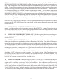
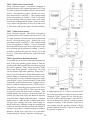
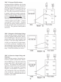
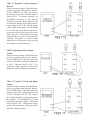
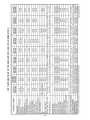
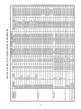
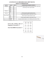
Point-MAN
RV GENERATOR
SERVICE TOOL
MODEL 361
OPERATORS
MANUAL
FLIGHT SYSTEMS
505 Fishing Creek Road Dock 16 Lewisberry, PA 17339 USA
717-932-9900
Fax: 717-932-9925
www.flightsystems.com
Issued 1/26/11 - Printed in USA
TABLE OF CONTENTS:
Introduction and Product Description
1
Installation
1-4
Adjustments 5
Diagnostic LED Indicators 6
Sequence of Operation
6
Troubleshooting
7
Technical Assistance, Repair Service, Warranty
7
Accessories, Companion Products
8
RPM Programming and Calibration (Fig 1) 8
Inputs and Outputs as shown on Faceplate (Fig. 2) 9
Inputs and Outputs Wiring Diagram (Fig. 3) 9
NPFA 110 Charts 10
NPFA 110 Information Sheet 11
Note: Many of the tests you can perform with
the Point-MAN require a multi-meter that has
diode, capacitance and frequency (Hz) ranges.
Almost all RV and Generator Service shops use
these; if you do not have a multi-meter, they can
be purchased at most electronics distributors.
Rt: Point-MAN being used in conjunction with a
Fluke Multi-meter (not supplied)
RV GENERATOR TROUBLESHOOTING with the Point-MAN
HOW DOES MY RV GENERATOR WORK?
What the Engine Control Board Does
Please refer to “Generic” wiring diagrams. The engine control board or module controls the ignition, fuel
pump, fuel solenoid (if equipped), field flash and starter. On LP models, it controls the flow of LP gas to
the throttle body. Some models prevent the engine from starting if there is insufficient oil quantity. Some
models prevent continued running if there is insufficient oil pressure. See test information chart. NOTE:
On models equipped with electronic governors (BGM, NHM Spec. B and later, 300-3764 control board),
the oil pressure signal to the control board comes from the governor module. Additionally, most models
require a voltage from the generator to keep the engine running once it has started. See test information
chart. All controls terminate cranking and lock out the starter after the engine has started. The battery
charging circuit, when equipped, is part of the control board on some models, and external on others.
NOTE: The controls used on Models KY (Spec. J), KYD (Spec. A), HGJAB and HGJAC are microprocessor-based and combine the functions of the engine control and regulator in one module (300-5046, 3271413 and 300-5374). Because these modules are complex and difficult to access without special tools and
adapters, they are not covered in these instructions.
What the Regulator Does
Please refer to “Generic” wiring diagrams. When the generator is first started, the control board sends the
field flash voltage (12 VDC) to the regulator on PIN 7 which applies it to the generator field (rotor) to initiate AC voltage buildup in the stator. The field flash voltage also initially powers the circuitry in the regulator before there is any AC voltage being generated. After the voltage builds up, the regulator is powered
by the quadrature stator winding (140-150 VAC). The regulator then maintains the generator output nearly
constant (within a few volts of 120 VAC) under conditions of varying load. It does this by sensing the 120
volts (PIN 2) and constantly adjusting the DC field (rotor) voltage (PINS 9 and 10) up or down, as needed. For example, if you turn on a light, the regulator would respond by increasing the field voltage only slightly
to compensate for the added load. If you turn on a microwave oven or an air conditioner, the regulator
would increase the field voltage by a much larger amount, in proportion to the heavier load. The regulator
has a built-in protection circuit that reduces the output voltage of the generator if the engine is running too
slow. The purpose of this feature is to protect your appliances from receiving full voltage at the lowered
frequency, as this can cause damage to motors and transformers. Normal Starting Sequence
This is what normally happens when you start your genset. Pressing and holding the start switch causes the
control board to send 12 volts to the ignition, fuel pump, choke heater, start solenoid and field flash circuits. The engine then cranks and starts. Oil pressure and generator voltage build up within 1-2 seconds. This
causes the control board to keep sending 12 volts to the ignition, fuel pump and choke heater while cutting
off 12 volts to the starter solenoid and field flash circuits. The start switch can then be released and the engine keeps running. Some models differ slightly in operation. On models equipped with magneto ignition
(KV, Spec. C-F; KY, Spec. A-E), the control board un-grounds the magneto kill circuit. Model KY, Spec.
B-E uses a fuel solenoid in addition to the fuel pump. Models fueled by LP gas use a fuel shutoff solenoid
valve instead of a fuel pump. Several conditions can prevent the engine from starting/running and are covered under “Troubleshooting Using the Point-MAN” below.
1
Normal Stopping Sequence
This is what happens when you stop your genset. Pressing and holding the stop switch for a few seconds
causes the control board to cut off the 12 volts to the ignition and fuel pump (and/or fuel solenoid valve) causing the engine to stop. On models equipped with magneto ignition, the control board grounds the magneto
kill circuit. Several conditions can cause the engine to stop by itself and are covered in the troubleshooting
procedures below.
TROUBLESHOOTING USING the Point-MAN
The Model 361 Point-MAN can be used with most popular Onan® RV generators (see Point-MAN Application List below) and provides easy access to the eight key regulator circuits needed for troubleshooting (see
“Regulator Pin Functions” below). The Point-MAN simply plugs in between the generator and the regulator. To get started, refer to “Generic” wiring diagrams and the test information chart for information specific to
the control board part number on your generator. If you don’t know the control board part number, check
the board itself and/or consult the Application Chart. Although a fair amount of troubleshooting can be done
with access to the regulator only, a few tests require probing of other circuits.
The Point-MAN can be used with the following Onan® RV and Commercial generator models:
Emerald Series, Model BGE, Spec. F and later Emerald Series, Model BGEL, Spec. E and later
Emerald Series, Model NHE, Spec. D and later
Emerald Series, Model NHEL, Spec. D and later
Marquis Series, Model BGM, Spec. A and later
Marquis Series, Model NHM, Spec. A and later
Microlite Series, Model KV, Spec A and later
Microlite Series, Model KY, Spec A thru H
Camp Power Series, Model KVC, Spec A
Camp Power Series, Model KVD, Spec A
Emerald Commercial Series, Model BGD, Spec. A thru H
Emerald Commercial Series, Model BGD, Spec. J and later (requires adapter kit)
Emerald Commercial Series, Model NHD, Spec. A thru H
Emerald Commercial Series, Model NHD, Spec. J and later (requires adapter kit)
Please note: Our G-MAN service tool is much more comprehensive and allows troubleshooting of the entire
system (generator, control board, regulator and more) and includes a built-in megger for insulation testing.
This troubleshooting guide assumes that the person doing the work has basic mechanical skills and is familiar
with electrical troubleshooting procedures using a multi-meter. Having a practical knowledge of RV generators is helpful, but not absolutely necessary.
CAUTION: Dangerous voltages (up to 200V) are present at the test jacks on the front of the
Point-MAN when the generator is running. Take suitable precautions.
DISCLAIMER: Generator servicing can present certain hazards such as cuts, burns, electric shock, fire,
and exposure to exhaust fumes. Take suitable precautions. Flight Systems will not assume any liability
for personal injury or damage to equipment or property as a result of using this Troubleshooting Guide
or the Point-MAN service tool.
2
Getting the Engine Running
Before proceeding with any evaluation of the controls, regulator or generator, the Onan® engine must have
oil and fuel, be in running condition and the 12-volt battery charged. The electronic governor, 151-0752, on
Models BGM and NHM, Spec B and later, must be functioning properly. This guide does not cover engine
maintenance and repair procedures (please refer to the applicable Onan® Service Manual for this information). The most common engine problems are caused mainly by lack of use and/or lack of regular monthly
exercise and include the following:
•
•
•
•
•
•
•
•
•
Low battery voltage because of insufficient charge, worn out battery, faulty cables (partly broken or corroded) or poor connections, resulting in slow cranking and hard starting.
Old or contaminated fuel that has gummed up the lines, fuel filter and carburetor. This can cause clogged jets (mixture too lean) and/or a stuck carburetor float resulting in an improper mixture (too rich or too lean) or flooding.
Weak spark and/or fouled spark plug(s) causing hard starting and rough running.
Stuck automatic choke causing an excessively rich mixture and smoking.
Stuck oil pressure switch causing shutdown as soon as the start button is released.
Dirty air filter, causing an excessively rich mixture and smoking.
Low oil level preventing starting on models equipped with low oil level switch.
Wiring harness damage from rodents chewing on the wires.
Corrosion of control board or connections from salty air or road chemicals.
FOLLOW THESE STEPS:
1.
CHECK OIL Check engine oil level before starting. 2.
GAIN ACCESS Remove panel or cover to gain access to the control board. Some disassembly may be required. The exact procedure depends on the model.
3.
CHECK BATTERY VOLTAGE Connect the negative voltmeter lead to GROUND and the posi-
tive lead to the positive battery cable on the starter solenoid and read the battery voltage. The same reading should be obtained at the BATTERY POSITIVE pin of the control board. A fully charged battery in good condition should read 12.6 to 12.8 VDC. Charge the battery if necessary.
4.
CHECK CRANKING Try to start the engine. If it does not crank, check the control fuse (5A Slo Blo, except models with electronic governor 10A). If the fuse is good, jumper the positive battery post to
the coil terminal on the start solenoid. If the engine cranks, there is a poor connection, wiring damage or
the control board is defective. If the engine cranks when the BATTERY POSITIVE pin is jumpered to the
START SOLENOID pin on the control board, the board is defective. NOTE: The battery voltage should not go below 9.5 VDC during cranking.
5.
CHECK SPARK If the engine cranks but does not start, remove a spark plug and check for spark during cranking (spark plug must be grounded). Temporarily jumper the ignition coil positive to the starter
solenoid positive terminal, or jumper the BATTERY POSITIVE pin to the IGNITION pin on the control
board. If you now have spark, there is a poor connection, wiring damage or the control board is defective. To
determine if it is the control board, check for 12 volts at the IGNITION pin during cranking. Other problems
such as dirty /worn points or a defective coil can cause loss of spark. On models where the oil level switch
is hard-wired to the magneto (KV Spec. C-F, KVC and KVD), low oil level or a stuck switch will inhibit
the spark and prevent starting. On these models, it may be necessary to temporarily disconnect the oil level
switch if it is stuck closed and not opening. To check the level switch, unplug the control board and verify that
the MAGNETO KILL circuit on the control harness is not grounded. Refer to the Troubleshooting Chart.
3
6.
CHECK FUEL SYSTEM If the engine cranks and has spark but does not start, the problem is likely
fuel related. This can be confirmed by injecting a small amount of starting fluid into the air intake. If the
engine fires and tries to run, it is starving for fuel. Listen for the fuel pump running during cranking. Check
for 12 volts at the FUEL PUMP pin on the control board during cranking. If there is no voltage, the control
board is defective. The pressure and flow of the fuel pump (and fuel filter) can be checked by temporarily
disconnecting the fuel line to the carburetor and jumpering the FUEL PUMP pin on the control plug to battery
positive. Take adequate precautions when handling fuel. If pressure and flow are normal, reconnect fuel line. Note: If the generator has not been run for several months, the carburetor float may be stuck closed and /or the
jets and needle valves may be gummed up by old fuel that has turned to varnish. These conditions interfere
with normal fuel delivery. The automatic choke may be stuck closed or binding so that it does not open as the
choke heater warms up. On Models BGM and NHM spec. B and later, make sure that the electronic governor
goes to full throttle one second after cranking begins. Any of these conditions will prevent the engine from
starting or running smoothly and must be corrected before proceeding.
7.
CHECK IF ENGINE KEEPS RUNNING The most common complaint is that the engine starts but
will not keep running when the START switch is released. This happens because the control board will not
allow the engine to continue running if the generator is not producing voltage or if the oil pressure signal is
not present. See CONDITIONS REQUIRED TO KEEP RUNNING on the test information chart for your
model. If the engine will not keep running, refer to “Test Procedures Using the Point-MAN” below and do
the following:
A1. Generator AC Output Use the Point-MAN to check the generator AC output voltage as soon as the engine starts (TEST 14). Models showing “B1-B2 Volts” or “L1 AC Volts” under CONDITIONS REQUIRED
TO KEEP RUNNING need this AC voltage at the control board terminals to keep running. Read between
the points shown on the test information chart. If AC voltage is at least being produced at start up, proceed
directly to “B” below. A2. Field Flash If there is no AC voltage, use the Point-MAN to check for field flash voltage (TEST 9). If
the field flash voltage is not present, the control board or wiring could be defective. To eliminate the wiring,
check continuity between the FIELD FLASH pin of the control board (see Pin Assignment Chart) and pin 7
of the regulator. If the wiring is good, the control board is defective. If the field flash voltage is present, the
problem is in the regulator or field circuit.
A3. Field Circuit Use the Point-MAN to check the field circuit resistance and isolation (TEST 1 and TEST
4) Also note “Special Rotor Resistance Tests” (TEST 8). If these reading are all good, the regulator is likely
defective.
A4. External Field Flash To confirm that the regulator is defective, turn off the generator’s AC circuit
breaker(s) and perform the external field flash test (TEST 10). If the generator voltage builds normally when
the voltage is applied to PIN 7, the problem is still in the control board or wiring and the regulator is OK. If
not, perform TEST 11 where the field flash voltage is applied at PIN 9 through a diode. CAUTION: DO NOT attempt this test without the diode. If you do, there will be fireworks! Remove the
12 volts within 1-2 seconds after the engine starts. If the genset now continues to run and produces normal
AC voltage, the generator is OK and the regulator is defective. If the genset does not continue to run but
produces about 40-50 VAC, again the generator is OK and the regulator is defective. The generator may
be checked alone without the regulator connected (TEST 12). The quadrature stator voltage may also be
checked under conditions of external excitation (TEST 16) except the voltage will only be 55-60 VAC. If
little or no AC voltage is produced, the generator may have a problem that is beyond the scope of this troubleshooting guide. Re-check all wiring for security and signs of damage. Perform resistance tests (TESTS 1
through 8). It may be necessary to take the unit to a qualified repair shop. 4
B. Check the oil pressure switch as soon as the engine starts. Models showing “LOP to GND” under CONDITIONS REQUIRED TO KEEP RUNNING need the oil pressure switch to be closed to ground when running. If the voltage on the LOL/LOP SW pin of the control board does not go to near zero, the switch is not
closing. These switches sometimes stick open if the generator has not been used or exercised often enough. Multiple start/stop cycles and/or tapping on the oil pressure switch will sometimes fix it. It may be necessary to temporarily jumper the switch to ground to keep the engine running. This can be done at the switch
or at the OIL LOL/LOP SW pin on the control board. Models showing “LOP Open” under CONDITIONS
REQUIRED TO KEEP RUNNING have electronic governors and require the low oil pressure switch to be
closed at starting but open during running. When the switch opens, the governor module places a ground on
the oil pressure input of the control board (P1-5). It is OK to temporarily ground P1-5 on this model to keep
the engine running. NOTE: See chart for oil pressure and oil level switch locations.
C. If there is AC voltage present on B1-B2 or L1 AC, as applicable, and the correct oil pressure/level signal is
present at the OIL LOL/LOP SW input of the control board, and the engine will not keep running, the control
board is defective. 8.
CHECK REGULATOR RESPONSE TO LOAD After the engine is running properly and stays
running, check the regulator field voltage output as load is added (TEST 13). A proper response to this test
is necessary to pass TEST 14. Also, if the frequency (proportional to RPM) is not being held nearly constant
from no-load to full load, check the governor (see 11 below).
9.
CHECK VOLTAGE/FREQUENCY ROLL-OFF If all other regulator functions are working properly, chances are very good that the voltage/frequency roll-off is also working. However, it is a good idea to
check it (TEST 15).
10.
CHECK AUTOMATIC CHOKE After the engine has been running for several minutes, the electric
choke heater should begin to open the choke (observe the position of the linkage). The choke will take longer
to open fully in cold weather. If the choke does not open, it is either stuck or the choke heater is not working. The choke mechanism can be freed up and maintained with a high temperature penetrating lubricant such as
“Mouse Milk.” If the choke heater is not working, the problem is most likely a high resistance due to corrosion, a poor connection, a damaged wire or an open heater element. Remove the round plastic cover and
notice if the choke heater has one wire or two. If it has one wire, remove it and measure the resistance at the
heater terminal to ground or the frame. This should be 15-20 ohms. Also, the wire going to the choke heater
should have 12 VDC whenever the engine is running. If not, check the wiring. If the heater has two wires
(BGE prior to spec K), remove one wire and measure the resistance between the two heater terminals. This
should be 15-20 ohms. With both wires connected to the choke heater and the engine running, there should
be 16-18 VAC between the terminals. If not, check the wiring.
11.
CHECK GOVERNOR If the engine surges or “hunts” (does not stay at a constant RPM), the cause
is likely a gummed-up carburetor or an improperly adjusted governor. If the generator is “high time”, the
surging could be caused by excessive wear in the governor linkage. These conditions should be corrected. Refer to the appropriate Onan Service Manual for repair procedures. If your multi-meter has a “Frequency”
or “Hz” range, you can check the RPM by measuring the frequency of the 120 VAC on the Point-MAN, PIN
2 and 3 (TEST 14), or at an AC outlet. It should be 60-62 Hz at no-load and not fall below 58 Hz at full load. The electronic governor (Marquis only) should hold the frequency close to 60 Hz under all conditions.
5
Test Procedures Using the Point-MAN (referred to above)
Generator Winding Resistance Tests
TEST 1 Field (rotor) Resistance
Setup: Generator stopped. Point-MAN
connected to generator harness only, regulator disconnected. Measure the resistance
between PIN 9 and PIN 10. This reading
includes the resistance of the rotor itself, the
brushes, slip rings and wiring and should be
between 22 and 28 ohms (slightly higher
when hot). A much lower resistance indicates a partially shorted rotor. This is serious, as the rotor will have to be replaced. A much higher resistance indicates dirty
slip rings and/or brush problems. A reading
of several meg ohms or “infinity” indicates
an open rotor, a stuck or worn out brush, or
a damaged wire (likely from chewing rodents). A high resistance reading (up to 200-300 ohms) is most common and is usually corrected by simply
cleaning the slip rings. This is done with the generator running using a tool such as the Slick Stick. Maintaining proper field circuit resistance is very important. A high resistance will cause the regulator to work
harder and may result in its premature failure. Also, the slip rings will run hotter which will result in further
deterioration of their contact surfaces.
NOTE: There are other special rotor resistance tests that are performed under certain conditions with the
generator running. These are covered below under “Special Rotor Resistance Tests”
TEST 2 Main Stator Resistance
Setup: Generator stopped. Point-MAN connected to generator harness only, regulator
disconnected. Measure the resistance between PIN 2 and PIN 3. This reading includes the resistance of the stator itself and
the wiring and should be between 0.0 and 0.2
Ohms. Note: It is difficult to obtain an accurate reading with a resistance this low. Make
sure that your meter reads “zero” when the
test leads are touched together. If not, note
the test lead resistance and subtract it from
your readings. A high resistance reading can
be caused by a poor connection or a damaged wire. Note: A partial short in the main stator
winding is nearly impossible to detect with a multi meter.
6
TEST 3 Quadrature Stator Resistance
Setup: Generator stopped. Point-MAN connected to generator harness only, regulator
disconnected. Measure the resistance between PIN 11 and PIN 12. This reading includes the resistance of the stator itself and
the wiring and should be between 2.2 and 2.5
Ohms. Note: It is difficult to obtain an accurate reading with a resistance this low. Make
sure that your meter reads “zero” when the
test leads are touched together. If not, note
the test lead resistance and subtract it from
your readings. A high resistance reading
usually means there is a poor connection or
a damaged wire. A poor connection or damaged wire can get very hot when a load is
placed on the generator, and could present a
fire hazard.
TEST 4 Field (rotor) Ground Fault
Setup: Generator stopped. Point-MAN connected to generator harness only, regulator
disconnected. Measure the resistance between PIN 9 and PIN 3. This reading should
be several megohms or “infinity.” If not, it
is possible that an insulation fault (a ground)
exists in the rotor between the windings and
the shaft. It may be necessary to remove the
rotor, clean it, dry it and re-test it. If the fault
is still present, replace the rotor.
TEST 5 Quadrature Stator Ground Fault
Setup: Generator stopped. Point-MAN connected to generator harness only, regulator disconnected. Measure the resistance
between PIN 11 and PIN 3. This reading
should be several megohms or “infinity.” If
not, it is possible that an insulation fault (a
ground) exists between the windings and the
frame. It may be necessary to remove the
generator, clean it, dry it and re-test it. If
the fault is still present, replace the stator assembly.
7
TEST 6 Main Stator Ground Fault
Setup: Generator stopped. Point-MAN connected to
generator harness only, regulator disconnected, T3 and
T4 stator terminals disconnected from ground block
and AC circuit breaker(s) open. Measure the resistance between PIN 2 and PIN 3. This reading should
be several megohms or “infinity.” If not, it is possible
that an insulation fault (a ground) exists in the stator
between the windings and the frame. It may be necessary to remove the generator, clean it, dry it and re-test
it. If the fault is still present, replace the stator assembly.
TEST 7 Main Stator Isolation
Setup: Generator stopped. Point-MAN connected to
generator harness only, regulator disconnected, T3 and
T4 stator terminals disconnected from ground block
and AC circuit breaker(s) open. Measure the resistance between PIN 2 and PIN 11. This reading should
be several megohms or “infinity.” If not, it is possible
that an insulation fault exists in the stator between the
main windings and the quadrature winding. It may be
necessary to remove the generator, clean it, dry it and
re-test it. If the fault is still present, replace the stator
assembly.
TEST 8 Special Rotor Resistance/Isolation
It is possible for an insulation fault to develop between
turns of the rotor winding (partial short) or from the
winding to the shaft (ground) that only shows up when
the rotor is spinning. These faults are called “flying
shorts” and “flying grounds”, respectively. The rotor
can also become open when spinning (“flying open”). These types of faults can be further influenced by temperature changes. Fortunately, their occurrence is rare,
but when they do occur, troubleshooting them can be
quite difficult. Setup: Generator stopped. Point-MAN
connected to generator harness only, regulator disconnected. Using an analog type meter (VOM) such as a
Simpson 260, connect the positive meter lead to PIN 9
and the negative lead to PIN 10. Make sure the meter
is properly zeroed and measure the resistance. This
reading includes the resistance of the rotor itself, the
brushes, slip rings and wiring and should be between
22 and 28 ohms (slightly higher when hot). Using an
analog meter is a must because a digital multi-meter
will give false readings due to the small voltage induced in the rotor windings during the spinning part
of this test. Start the generator and note any change of
resistance, up or down. A significant drop in resistance
indicates a flying short, especially if it is repeatable. A high reading or “infinity” indicates a flying open.
8
A slight apparent rise (1-3 ohms) is normal and is
due to the small induced voltage in the rotor influencing the VOM. Repeat the test with the positive lead on PIN 9 and the negative lead on PIN 3. The meter should read “infinity” with the generator
stopped or running. If the resistance drops below
one megohm with the generator running, a flying
ground condition may exist. A defective rotor must
be repaired or replaced
Generator Voltage and Field Flash Tests
CAUTION: To prevent possible damage to external circuits or appliances, MAKE SURE
that AC CIRCUIT BREAKER IS OFF during control and generator testing as generator
output voltage could rise significantly above normal.
TEST 9 Field Flash Voltage
Setup: Generator stopped. Point-MAN connected to
regulator & generator harness. Set the DMM for DC
Volts and connect the positive lead to PIN 7 and the
negative lead to PIN 6. Press the start switch. During cranking and as the generator starts and builds
voltage, the field flash voltage should be 10-11 VDC
momentarily. Disregard this voltage after the generator is running. If the field flash voltage does not appear at least momentarily, the control board is faulty or
there is an open circuit between the control board field
flash output pin and the regulator PIN 7. This may
confirmed by providing field flash voltage externally.
TEST 10 External Field Flash via Pin 7
Setup: Generator stopped. Point-MAN connected to
regulator & generator harness. Set the DMM for AC
Volts and connect the positive lead to PIN 2 and the
negative lead to PIN 3. Connect a test lead (24” to
48”) to PIN 7. NOTE: Most models (see chart) require the generator to be producing voltage in order
to remain running when the start switch is released. Therefore, the external field flash voltage needs to
be supplied as the generator is being cranked and
removed as soon as voltage builds. Press the start
switch and at the same time touch the test lead to the
positive battery terminal on the start solenoid or other
convenient source of 12 VDC. If the generator starts,
builds voltage and continues to run when external
field flash is momentarily applied but not otherwise,
then it may be concluded that the regulator is OK and
is not getting field flash on PIN 7. The cause could
be a faulty control board or wiring. If field resistance
tests (see above) are satisfactory and voltage does not
build, then it is likely that the regulator is faulty.
TEST 11 External Field Flash via Pin 9
To confirm a faulty regulator proceed as above except
apply the field flash voltage to PIN 9 (Field +) through
a diode instead of directly to PIN 7. The diode should
be rated at 1 Amp, 400V minimum (1N4004 or better)
and make sure its banded end (cathode) is toward PIN
9. DO NOT ATTEMPT THIS TEST WITHOUT
THE DIODE! If the generator now builds voltage,
the regulator is definitely faulty.
9
TEST 12 External Field Excitation
On Marquis BGM or NHM Spec. B-G (using
control board P/Ns 300-3764, 300-5342 or
300-4902 and electronic governor P/N 1510752), the engine will continue to run even
though the generator is not producing voltage. This allows external field excitation to
be applied without the regulator connected. Setup: Generator running. Point-MAN connected to generator harness only. Regulator disconnected. Set the DMM for AC
Volts and connect the positive lead to PIN
2 and the negative lead to PIN 3. Connect
a test lead (24” to 48”) to PIN 9. Touch the
test lead to the positive battery terminal on
the start solenoid or other convenient source
of 12 VDC. The generator should produce
40-50 VAC.
TEST 13 Regulator Field Output Voltage
Setup: Generator running. Point-MAN connected to regulator and generator harness. Set the DMM for DC Volts and connect the
positive lead to PIN 9 and the negative lead
to PIN 10. The field voltage should be 2944 VDC at no load and rise to approximately 60 VDC at full load. Readings will be
somewhat higher when the generator is hot. Excessively high readings indicate dirty slip
rings. Check field resistance (see above).
TEST 14 Generator Output Voltage and
Frequency
Setup: Generator running. Point-MAN connected to regulator and generator harness. Set the DMM for AC Volts and connect the
positive lead to PIN 2 and the negative lead
to PIN 3. The output (main stator) voltage
should be 118-126 VAC at no load and not
fall below 115 VAC at full load. To measure
frequency, set the DMM to “Frequency” or
“Hz” and read 60-62 Hz at no load and 5860 Hz at full load. Adjust the governor as
necessary. Refer to applicable Onan service
manual for your model.
10
TEST 15 Regulator Voltage/Frequency
Roll-off
Setup: Generator running. Point-MAN connected to regulator and generator harness. Set the DMM for AC Volts and connect
the positive lead to PIN 2 and the negative
lead to PIN 3. To measure frequency, set
the DMM to “Frequency” or “Hz” and read
60-62 Hz at no load. Apply slight pressure
to the throttle linkage so that the frequency
(speed) drops below 57 Hz. Note the sound
of the engine at this speed. Set the DMM
to AC Volts and verify that the output voltage starts to fall off as the speed slows down
below this point. The reduction of voltage
with frequency or speed is a function of the
regulator. Its purpose is to protect loads
connected to the generator from receiving
full voltage at reduced frequency.
TEST 16 Quadrature Stator Output
Voltage
Setup: Generator running. Point-MAN connected to regulator and generator harness. Set the DMM for AC Volts and connect the
positive lead to PIN 11 and the negative lead
to PIN 12. Measure 140-150 VAC. Low
quadrature voltage indicates a fault in the
quadrature stator winding of the generator.
TEST 17 Capacitor Voltage and Ripple
Voltage
Setup: Generator running. Point-MAN connected to regulator and generator harness. Set the DMM for DC Volts and connect the
positive lead to PIN 9 and the negative lead
to PIN 6. Measure 190-205 VDC. This is
the rectified and filtered voltage that powers
the regulator. Set the DMM for AC Volts
and measure the ripple voltage. This should
not exceed 8.0 VAC. A high ripple voltage
and/or a low capacitance value (see above)
indicates a faulty regulator.
11
Regulator Internal Component Tests
The following tests enable you to evaluate some of the internal components of the regulator that are connected directly to its terminals. A failure of any of these tests would indicate a regulator problem (except as
noted). However, passing all of these tests does not necessarily mean that the regulator is good, as only a
small percentage of the unit is being tested. This group of tests is by no means a complete or a functional test. A DMM with a “Diode” and a “Capacitor” range is very handy for performing these tests however an analog
VOM (such as the Simpson 260) will still give
some useful information. On diode forward tests,
the VOM will likely read 10 to 100 ohms, depending on the meter, and “infinity” on reverse tests. TEST 18 Output TVS Diode and Transistor
Setup: Generator stopped. Point-MAN connected to regulator only, generator harness disconnected. Set the DMM for “Diode” and connect
the positive lead to PIN 6 and the negative lead to
PIN 9. Read forward continuity and a voltage of
approximately 0.5 VDC. Reverse the leads and
read “infinity.”
TEST 19 Field Free-wheeling Diode
Setup: Generator stopped. Point-MAN connected to regulator only, generator harness disconnected. Set the DMM for “Diode” and connect
the positive lead to PIN 10 and the negative lead
to PIN 9. Read forward continuity and a voltage
of approximately 0.5 VDC. Reverse the leads
and read “infinity.”
TEST 20 Field TVS Diode (Not used on all
models)
Setup: Generator stopped. Point-MAN connected to regulator only, generator harness disconnected. Set the DMM for “Diode” and connect
the positive lead to PIN 6 and the negative lead to
PIN 10. Read forward continuity and a voltage of
approximately 0.9 VDC. Reverse the leads and
read “infinity.”
12
TEST 21 Field Flash Diode
Setup: Generator stopped. Point-MAN connected to regulator only, generator harness
disconnected. Set DMM for “Diode” and
connect the positive lead to PIN 7 and the
negative lead to PIN 9. Read forward continuity and a voltage of approximately 0.6
VDC. Reverse the leads and read “infinity.”
TEST 22 Bridge Rectifier
Setup: Generator stopped. Point-MAN connected to regulator only, generator harness
disconnected. Set the DMM for “Diode” and
connect the positive lead to PIN 11 and the
negative lead to PIN 9. Read forward continuity and a voltage of approximately 0.5
VDC. Reverse the leads and read “infinity.” Connect the positive lead to PIN 12 and the
negative lead to PIN 9. Read forward continuity and a voltage of approximately 0.5
VDC. Reverse the leads and read “infinity.”
TEST 23 Ground to Capacitor (-) Diode
Setup: Generator stopped. Point-MAN connected to regulator only, generator harness
disconnected. Set DMM for “Diode” and
connect the positive lead to PIN 6 and the
negative lead to PIN 3. Read forward continuity and a voltage of approximately 0.6
VDC. Reverse the leads and read “infinity.”
13
TEST 24 Capacitor Value
Setup: Generator stopped. Point-MAN
connected to regulator only, generator
harness disconnected. Set the DMM for
“Capacitor” and connect the positive lead
to PIN 9 and the negative lead to PIN 6. The nominal value of the capacitor is 220
uF. Read a minimum of 175 uF. A reading
higher than 220 uF is OK and is quite common. In this case, more is better!
Regulator Pin Functions
The following is a general description of the function of each of the 12 pins of the regulator and covers several models. The function of the pins is the same from model to model with the exception of PIN 1 and PIN
8. A few 60 Hz applications and many 50 Hz applications use an external potentiometer for voltage adjustment. The commercial version of the regulator (300-0911) uses a different 12-pin connector (Deutch) and
requires an adapter kit.
PIN 1 is used with PIN 5 when an external voltage adjustment potentiometer is connected on regulators 3050852 and 305-0897 only (primarily 50 Hz applications). When an external voltage adjustment potentiometer
is not used, PIN 1 is connected directly to PIN 5. All other regulators use PIN 4 for this function (see PIN 4
below) and PIN 1 is not used and is not connected. PIN 1 is not used for troubleshooting purposes, does not
appear on the Point-MAN and feeds straight through.
PIN 2 (YELLOW) is used to sense the AC output voltage of the generator. It is connected to the “hot” side
(T1, T3) of the main stator. The voltage on PIN 2 is measured with respect to PIN 3 (AC LO and GND) and
should be between 118 and 122 VAC. PIN 2 is also used to check stator winding resistance and isolation.
PIN 3 (BLACK) is the common connection for AC LO or neutral, battery negative and frame ground. It is
the reference point for measuring the AC output voltage of the generator (see PIN 2 above). PIN 3 is also
used to check stator winding resistance and isolation.
PIN 4 is used with PIN 5 for connecting an external voltage adjustment potentiometer and is used on all
regulators except 305-0852 and 305-0897 (see PIN 1 above). Only a few 60 Hz regulators use an external
voltage adjust potentiometer connected between PIN 4 and PIN 5. On all others, PIN 4 is connected directly
to PIN 5. PIN 4 is not used for troubleshooting purposes, does not appear on the Point-MAN and feeds
straight through.
PIN 5 is the internal negative for the regulator and is also common with PIN 6 and the capacitor negative terminal. PIN 5 is not used for troubleshooting purposes, does not appear on the Point-MAN and feeds straight
through.
PIN 6 (BLACK) is the internal negative for the regulator and is common with PIN 5 and the capacitor negative terminal. It is the reference point for measuring the field flash and capacitor voltages.
14
PIN 7 (GREEN) is the input for the field flash voltage sent by the control board during cranking and until
the generator builds output voltage. The field flash accomplishes two things: It initially powers the regulator’s internal circuitry and it provides sufficient field excitation for the generator to build voltage to the point
where field flash is no longer needed. Field flash and cranking are terminated simultaneously when the run
relay in the control board energizes. The field flash voltage is measured with respect to the regulator internal
negative PIN 6 above.
PIN 8 is the positive capacitor terminal on some regulator models. On other models, it is not connected. On the metal-cased regulators 305-0826 (Marquis) and 305-0911 (Commercial), PIN 8 is connected to case
ground. PIN 8 is not used for troubleshooting purposes, does not appear on the Point-MAN and feeds straight
through.
PIN 9 (RED) is the positive terminal of the field and the capacitor and is also common to PIN 8 on some
models. The capacitor voltage is measured on PIN 9 with respect to PIN 6. The field voltage is measured on
PIN 9 with respect to PIN 10. The field voltage normally varies between 30 VDC at no-load to 60 VDC at
full load. PIN 9 is also used with PIN 10 and PIN 3 to check field (rotor) resistance and isolation.
PIN 10 (BLUE) is the negative terminal of the field. The average field voltage is measured on PIN 9 with
respect to PIN 10.
PIN 11 (WHITE) is one terminal of the quadrature stator winding that supplies power to the regulator. PIN
11 is also used to check quadrature stator winding resistance and isolation.
PIN 12 (WHITE) is one terminal of the quadrature stator winding that supplies power to the regulator. PIN
12 is also used to check quadrature stator winding resistance and isolation.
Onan® RV Generator Troubleshooting, Application & Other Charts
found on following pages
15
16
TEST INFORMATION FOR TROUBLSHOOTING ONAN® RV GENERATORS
17
APPLICATION CHART FOR 120V 60Hz ONAN® RV GENERATORS
Location of Oil Pressure/Level Switches on
Onan® RV Generators
Front view (mating side) of
Regulator Connector J1.
Also Point-MAN Connector J1
18
TECHNICAL ASSISTANCE
If you require assistance during operation of the Model 361, please call our Technical Service Department at 717 932 9900 from 8am to 4:30pm ET, M-F.
ONLINE TROUBLESHOOTING GUIDE
Our Onan® RV Gen Set Troubleshooting Guide can be downloaded free on our site at
http://www.flightsystems.com/pdf/onanrvtshootgd608.pdf
REPAIR SERVICE
Should the Model 361 suffer a problem when out of warranty, repair service is available from the manufacturer at reasonable rates. Ship unit to Flight Systems, 505 Fishing Creek Road, Lewisberry, PA 17339
USA. Attn: Dock 16
WARRANTY
The Model 361 is warranted to be free from defects in materials and workmanship for a period of two years
from the date of shipment.
FLIGHT SYSTEMS’ liability is limited to the repair or replacement of defective product within the warranty period, and does not cover installation or removal costs incurred or possible damage to other equipment
(including generator sets and transfer switches) as a result of a malfunction of the Model 361.
If, in the opinion of FLIGHT SYSTEMS (or its authorized agent) the malfunction of the Model 361 was caused
by abuse, misuse or improper installation, the warranty claim will be disallowed and established repair rates
will apply.
Units should be shipped, freight charges prepaid to FLIGHT SYSTEMS, 505 Fishing Creek Rd, Lewisberry,
PA 17339, USA Attn: Dock 16
19