1
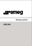
NIC-EBS/L/V/i Network managed G.703 to Ethernet Converter Installation and Operation Manual Code:C047b-004-00 HW: C047-100-20 C047b-100-21 HW: C049-100-20 C049-101-00 HW: C049-100-21 C049b-100-21 SW:SC047-100-20 C049-101-01 NIC-EBS/L/V/i Installation and Operation Manual Notice This manual contains information that is proprietary to CCOM Communication Technology Co.Ltd. No part of this publication may be reproduced in any form whatsoever without prior written approval by CCOM. No representation or warranties for fitness for any purpose other than what is specifically mentioned in this manual is made either by CCOM Co. Ltd. Or its agents. CCOM Keep the further expository and amending right for the manual. For further information contact CCOM Communications at the address below or contact your local distributor. CCOM Communications Technology Co.,Ltd. First unit, No.1 building, Part A, Zhaowei industry park, No.14 Jiuxianqiao road, Chaoyang district, Beijing, China Postalcode:100016 TEL:86-10-64360088 FAX:86-10-64378389 CCOM Communication Technology Co.Ltd. Http://www.ccom.com.cn Page 2 of 32 NIC-EBS/L/V/i Installation and Operation Manual Warranty This CCOM product is warranted against defects in material and workmanship for a period of one year from date of shipment. During the warranty period, CCOM, will, at is option, either repair or replace products which prove to be defective. For warranty service or repair, this product must be return to a service facility designated by CCOM. Limitation of Warranty The foregoing warranty shall not apply to defects resulting from improper or inadequate maintenance by Buyer, Buyer-supplied firmware or interfacing, unauthorized modification or misuse, operation outside of the environmental specifications for the product, or improper site preparation or maintenance. General Safety Precautions Transportation, Installation and Operation Avoid excessive vibration and shocks. Avoid contact with water, dust, and dirt. Avoid excessive direct sunlight. Ensure sufficient cooling. Prevent loose items from falling into the device. Main Powers Disconnect the power cord before opening the device. Use exclusively the supplied power supply the approved power cord. The power plug must be plugged into a properly grounded receptacle. An improperly wired receptacle could place hazardous voltage on accessible metal parts of the device. The mains supply must match the power specification of the device. Replace blown fuses exclusively with fuses of the same ratings. Do not work on the equipment during periods of lightning activity. Technical Support Before contacting with your support representative, please prepare to provide the complete serial number of the affected unit (refer to the according unit label). Version Number DATE Version CCOM Communication Technology Co.Ltd. Describe Http://www.ccom.com.cn Page 3 of 32 NIC-EBS/L/V/i Installation and Operation Manual Content 1 Chapter 1 Introduction......................................................................... 8 1.1 1.2 1.3 1.4 1.5 Overview..............................................................................................................................8 Versions...............................................................................................................................8 Applications .........................................................................................................................8 Features...............................................................................................................................9 Physical Description ............................................................................................................9 1.5.1 Front Panel of Stand Alone Unit...............................................................................................9 1.5.2 Rear Panel of Stand Alone Unit ................................................................................................9 1.5.3 Card Product ...........................................................................................................................10 1.6 Technical Specifications....................................................................................................10 1.6.1 E1 Interface.............................................................................................................................10 1.6.2 Ethernet interface....................................................................................................................11 1.6.3 Physical...................................................................................................................................13 1.6.4 Power Supply..........................................................................................................................13 1.6.5 Environment ...........................................................................................................................14 1.6.6 MTBF .....................................................................................................................................14 2 Chapter 2 Installation and Setup ....................................................... 15 2.1 2.2 2.3 Site Requirements and Prerequisites................................................................................15 Configuration .....................................................................................................................15 Installation and Setup of Standalone Unit.........................................................................17 2.3.1 To install NIC-EBS/L/V/i: ......................................................................................................17 2.3.2 Connecting the Interfaces .......................................................................................................17 2.3.3 Connecting the Power.............................................................................................................19 2.4 Installation and Setup of Card Unit ...................................................................................20 2.4.1 Installing the Card Unit into the NIC-iRACK Card Cage ......................................................20 2.4.2 Connecting the Interfaces .......................................................................................................20 3 Chapter 3 Operation.......................................................................... 21 3.1 3.2 Front Panel Indicators and Controls..................................................................................21 Operating Procedure .........................................................................................................22 3.2.1 Turning NIC-EBS/L/V/i On....................................................................................................22 3.2.2 Normal Indications .................................................................................................................22 3.2.3 Turning NIC-EBS/L/V/i Off ...................................................................................................22 3.3 Loopback Test ...................................................................................................................22 3.3.1 Local Analog Loopback (ANA)..............................................................................................23 3.3.2 Local Digital Loopback (DIG)................................................................................................23 3.3.3 BER Test (L/R) .......................................................................................................................23 3.4 SNMP Network Management............................................................................................25 3.4.1 SNMP Management Topology................................................................................................25 3.4.2 Main Function.........................................................................................................................25 CCOM Communication Technology Co.Ltd. Http://www.ccom.com.cn Page 4 of 32 NIC-EBS/L/V/i Installation and Operation Manual 3.4.3 SNMP Management................................................................................................................26 4 Chapter 4 Troubleshooting................................................................ 29 5 Supplement Pinouts .......................................................................... 31 CCOM Communication Technology Co.Ltd. Http://www.ccom.com.cn Page 5 of 32 NIC-EBS/L/V/i Installation and Operation Manual Figure Index FIGURE 1-1 POINT-TO-POINT APPLICATION .......................................................................................................................... 8 FIGURE 1-2 FRONT PANEL OF STAND ALONE UNIT .............................................................................................................. 9 FIGURE 1-3 REAR PANEL OF STAND ALONE UNIT .............................................................................................................. 10 FIGURE 1-4 CARD UNIT ..................................................................................................................................................... 10 FIGURE 2-1 DIP SWITCHES OF STAND ALONE UNIT........................................................................................................... 16 FIGURE 2-2 DIP SWITCHES OF CARD UNIT ........................................................................................................................ 16 FIGURE 2-3 REAR PANEL OF STAND-ALONE UNIT (AC VERSION) ....................................................................................... 17 FIGURE 2-4 REAR PANEL OF STAND-ALONE UNIT (DC VERSION) ....................................................................................... 18 FIGURE 2-5 E1 CONNECTORS ............................................................................................................................................. 18 FIGURE 2-6 DC POWER CONNECTION ................................................................................................................................ 19 FIGURE 2-7 NIC-IRACK FOR CARD UNITS ........................................................................................................................ 20 FIGURE 2-8 REAR PANEL OF CARD UNIT ............................................................................................................................. 20 FIGURE 3-1 FRONT PANEL OF STANDALONE UNIT ............................................................................................................. 21 FIGURE 3-2 FRONT PANEL OF CARD UNIT.......................................................................................................................... 21 FIGURE 3-3 LOCAL ANALOG LOOPBACK ........................................................................................................................... 23 FIGURE 3-4 LOCAL DIGITAL LOOPBACK ............................................................................................................................ 23 FIGURE 3-5 BER SYSTEM SINGLE-UNIT TEST.................................................................................................................... 24 FIGURE 3-6 BER SYSTEM TWO-BER TEST ....................................................................................................................... 24 FIGURE 3-7 NETWORK TOPOLOGY..................................................................................................................................... 25 CCOM Communication Technology Co.Ltd. Http://www.ccom.com.cn Page 6 of 32 NIC-EBS/L/V/i Installation and Operation Manual Table index TABLE 1-1 E1 INTERFACE SPECIFICATION.......................................................................................................................... 10 TABLE 1-2 OUTPUT JITTER OF E1 PORT ............................................................................................................................. 11 TABLE 1-3 INPUT JITTER OF E1 PORT................................................................................................................................. 11 TABLE 1-4 JITTER TRANSFER CHARACTERISTIC OF E1 PORT ............................................................................................. 11 TABLE 1-5 ETHERNET INTERFACE SPECIFICATION ............................................................................................................. 11 TABLE 1-6 LAN PORT WORKING MODE WHEN COOPERATING WITH PERIPHERAL EQUIPMENTS.......................................... 12 TABLE 1-7 THROUGHPUT TEST.......................................................................................................................................... 12 TABLE 1-8 PACKET LOSS TEST .......................................................................................................................................... 12 TABLE 1-9 LATENCY TEST ................................................................................................................................................ 13 TABLE 1-10 BACK- TO-BACK TEST ................................................................................................................................... 13 TABLE 1-11 PHYSICAL SPECIFICATION .............................................................................................................................. 13 TABLE 1-12 POWER SUPPLY SPECIFICATION ...................................................................................................................... 13 TABLE 1-13ENVIRONMENT................................................................................................................................................ 14 TABLE 2-1 SW3 OF STAND ALONE UNIT ............................................................................................................................ 16 TABLE 2-2 SWITCHES OF CARD UNIT ................................................................................................................................. 17 TABLE 3-1 FRONT PANEL INDICATORS AND CONTROLS .................................................................................................... 21 TABLE 4-1. TROUBLESHOOTING PROCEDURE .................................................................................................................... 29 G.703 120ΩRJ-45 CONNECTER PINOUTS ..................................................................................................................... 31 ETHERNET RJ-45 CONNECTER PINOUTS ........................................................................................................................ 31 RJ-45 PINOUTS FOR CAT 5 EIA/TIA-568-A ................................................................................................................... 31 RJ-45 PINOUTS FOR CAT 5 EIA/TIA-568-B ................................................................................................................... 31 CCOM Communication Technology Co.Ltd. Http://www.ccom.com.cn Page 7 of 32 NIC-EBS/L/V/i Installation and Operation Manual 1 Chapter 1 Introduction 1.1 Overview NIC-EBS/L/V/i is a type of high quality Ethernet-to-E1 converter. As an extended equipment of Ethernet, it could be used to connect two Ethernets transparently by PDH or SDH network and adapt to found remote network connection with a low cost. NIC-EBS/L/V/i has 1 10/100Base-T Ethernet interfaces with auto-negotiation function on Full/Half Duplex and 10/100M speed. NIC-EBS/L/V/i can learn the MAC address automatically that be connected and transmit just the datagram with the destination address in the remote Ethernet. So it can restrain the broadcast and advance the efficiency of the Ethernet. The transmitting speed is up to 2.048Mbps. Twin using of NIC-EBS/L/V/i at the application is suggested. 1.2 Versions The following versions of the unit are available: ¾ NIC-EBS/L/V/i/AC: a standalone unit, AC power supply. ¾ NIC-EBS/L/V/i/48: a standalone unit, -48VDC power supply. ¾ NIC-EBS/L/V/i/24: a standalone unit, +24VDC power supply. ¾ NIC-EBS/L/V/i/C: a plug-in card unit consisting of a front sub card and a back sub card for installation in the NIC-iRACK, 19-inch rack, holding up to 14 service cards. 1.3 Applications E1 Network LAN NIC-EBS/L/V/i NIC-EBS/L/V/i Figure 1-1 Point-to-Point application CCOM Communication Technology Co.Ltd. Http://www.ccom.com.cn Page 8 of 32 NIC-EBS/L/V/i Installation and Operation Manual 1.4 Features ¾ Standard: IEEE 802.3, 802.3u, 802.1Q, 802.1x, ITU-T G.703, G.742, G.823 ¾ Unframed Speed: 2048K Bit/s ¾ Support SNMP network management through central card unit fixed in NIC-iRACK ¾ E1 connector: 75Ω BNC/120Ω RJ-45 ¾ Ethernet Interface: RJ-45 jack, 10 /100Base-T interface, auto MDI-X ¾ Auto negotiation or force mode on Full/Half Duplex mode and 10/100M speed ¾ Support VLAN trunk and flow control functions ¾ Loop test function: ANA, DIG, REM ¾ Power supply: 90~220VAC, -36~-72VDC, +18~+36VDC ¾ Card style or stand alone style 1.5 Physical Description NIC-EBS/L/V/i is available as a standalone unit or as a rack-mount card for the NIC-iRACK. 1.5.1 Front Panel of Stand Alone Unit Figure 1-2 Front Panel of Stand Alone Unit The front panel includes 8 LEDs, which display the status of power, data flow, Ethernet link and E1 channel signal. Four front-panel push-buttons control 3 kinds of loopbacks and the display of remote Ethernet interfaces. For detailed description of the front panel, see Chapter 3. 1.5.2 Rear Panel of Stand Alone Unit CCOM Communication Technology Co.Ltd. Http://www.ccom.com.cn Page 9 of 32 NIC-EBS/L/V/i Installation and Operation Manual Figure 1-3 Rear Panel of Stand Alone Unit The back panel includes a power connector (AC or DC),a power switch, 4 Ethernet interface connectors, S3 DIP-switch and a E1 line connector. The NIC-EBS/L/V/i rear panel is described in greater detail in Chapter 2. 1.5.3 Card Product Figure 1-4 Card Unit 1.6 Technical Specifications 1.6.1 E1 Interface Table 1-1 E1 interface specification CCOM Communication Technology Co.Ltd. Http://www.ccom.com.cn Page 10 of 32 NIC-EBS/L/V/i Installation and Operation Manual Standard ITU-T G.703, G.704, G.823 and G.742 Framing Framed/Unframed connector BNC male connector for 75Ω coaxial cables; RJ-45 jack for 120Ω twisted pairs HDB3 Code Baud rate 2048 Kbps ± 50ppm Bit rate Unframed: 2.048M bps Framed: N*64k (N<=31) 75Ω for unbalanced (BNC, coaxial cable) Impedance 120Ω for balanced (RJ-45, twisted pair) Receiving sensitivity 0~-18dBm Transmit high voltage 2.37V± 10%, 75Ω; 3.00V± 10%,120Ω Transmit low voltage 0 ± 0.1V Transmitting distance 100m for coaxial cable, 300m for twisted-pair Table 1-2 Output Jitter of E1 port B1(20Hz~100KHz) <0.08 UI B2(18kHz~100KHz) <0.05 UI Table 1-3 Input Jitter of E1 port Frequency(Hz) 10 30.7 Jitter (UI) 63 130 500 1.2k 2.1k 3.7k 6.4k 11k 100k 26.7 14.6 6.04 4.22 3.83 3.7 3.1 2.8 0.7 20 30 Table 1-4 Jitter Transfer characteristic of E1 port Frequency(Hz) Jitter(UI) 1.6.2 20 45 65 130 260 500 1.2k 2.1k 100k -35.97 -42.71 -56.82 -64.43 -57.63 -57.50 -54.37 -55.12 -52.31 Ethernet interface Table 1-5 Ethernet interface specification Function support VLAN trunk and flow control Standard IEEE 802.3 Interface Ethernet and Fast Ethernet Link Speed 10/100Mbit/s, Auto-Negotiation/force mode Duplex Mode force or Auto-Negotiation on Half / Full Duplex Mode Connector RJ-45 jack, auto MDI-X Frame Length 64byte(least)/1536byte(most) MAC Address Capacity 1K MAC Address Update 5 Minutes 802.3u 802.1q CCOM Communication Technology Co.Ltd. Http://www.ccom.com.cn Page 11 of 32 NIC-EBS/L/V/i Installation and Operation Manual Table 1-6 LAN port working mode when cooperating with peripheral equipments LAN port setting peripheral equipments LAN port real working peripheral equipments real Effect mode setting mode mode working mode A/N A/N 100M FD 100M FD perfect 100M FD 100M FD 100M FD 100M FD perfect 10M FD 10M FD 10M FD 10M FD perfect 100M HD 100M HD 100M HD 100M HD perfect 10M HD 10M HD 10M HD 10M HD perfect A/N 100M HD 100M HD 100M HD good A/N 10M HD 10M HD 10M HD good A/N 100M FD 100M HD 100M FD unfitting A/N 10M FD 10M HD 10M FD unfitting NOTE: A/N(auto-negotiation) FD(full duplex) HD(half duplex) Table 1-7 Throughput Test Frame Size Passed 01 to 02 02 to 01 Rate(%) (pks/sec) (pks/sec) Total 100M -100M 100M -100M 64 100.00 148810 148810 297620 128 100.00 84459 84459 168918 256 100.00 45290 45290 90580 512 100.00 23496 23496 46992 1024 100.00 11973 11973 23946 1280 100.00 9615 9615 19230 1518 100.00 8127 8127 16254 1536 100.00 8033 8033 16066 Table 1-8 Packet Loss Test Frame Size Rate Tested(%) 01 to 02 (%) 02 to 01 (%) 100M -100M 100M -100M Average 64 100.00 0.000 0.000 0.000 128 100.00 0.000 0.000 0.000 256 100.00 0.000 0.000 0.000 512 100.00 0.000 0.000 0.000 1024 100.00 0.000 0.000 0.000 1280 100.00 0.000 0.000 0.000 1518 100.00 0.000 0.000 0.000 1536 100.00 0.000 0.000 0.000 CCOM Communication Technology Co.Ltd. Http://www.ccom.com.cn Page 12 of 32 NIC-EBS/L/V/i Installation and Operation Manual Table 1-9 Latency Test Frame Size Rate Tested(%) 01 to 02 (us)-CT Average (CT) 100M -100M 01 to 02 (us)-S&F Average (S&F) 100M -100M 64 100.00 100.3 100.3 95.1 95.1 128 100.00 110.6 110.6 100.4 100.4 256 100.00 131.1 131.1 110.6 110.6 512 100.00 172.0 172.0 131.1 131.1 1024 100.00 253.5 253.5 171.6 171.6 1280 100.00 294.8 294.8 192.3 192.3 1518 100.00 332.9 332.9 211.5 211.5 1536 100.00 335.7 335.7 212.9 212.9 Table 1-10 Back- to-Back Test Frame Size 01 to02 Burst Size Rate Tested(%) (frames) 02 to01 (frames) 100M -100M 100M -100M Total 64 100.00 297620 297620 595240 128 100.00 168918 168918 337836 256 100.00 90580 90580 181160 512 100.00 46992 46992 93984 1024 100.00 23946 23946 47892 1280 100.00 19230 19230 38460 1518 100.00 16254 16254 32508 1536 100.00 16066 16066 32132 1.6.3 Physical Table 1-11 Physical specification Height Width Depth Weight Stand-alone 44 mm/1.73 inch 197 mm / 7.76 inch 230 mm / 9.06 inch 1.1kg Card 144mm/5.67 inch 28mm/1.10 inch 250mm/9.84 inch 0.3kg Package 280mm/11.02 inch 310mm/12.20 inch 80mm/3.15 inch 1.0kg NIC-EBS/L/V/i/C Card Fit one slot in the NIC-iRACK card cage 1.6.4 Power Supply Table 1-12 Power supply specification 165~265 VAC, 50Hz, 5W, 1A fuse CCOM Communication Technology Co.Ltd. Http://www.ccom.com.cn Page 13 of 32 NIC-EBS/L/V/i Installation and Operation Manual 90~260 VAC, 50Hz, 5W, 1A fuse DC Source -48VDC source, -36~-72 VDC , 5W, 1A fuse +24 VDC source, +18~+36VDC , 5W, 1A fuse Power Consumption 1.6.5 4W Environment Table 1-13Environment Operation temperature Storage temperature Atmospheric pressure Humidity 0 -50°C -20~70℃ 70~106Kpa Up to 95%, non-condensing 1.6.6 MTBF MTBF (Media Time Between Fault): 70,000 hours CCOM Communication Technology Co.Ltd. Http://www.ccom.com.cn Page 14 of 32 NIC-EBS/L/V/i Installation and Operation Manual 2 Chapter 2 Installation and Setup This chapter describes installation and setup procedures for the standalone and card units. NIC-EBS/L/V/i is delivered completely assembled. It is designed for tabletop or 19-inch rack installation. After installing the unit, refer to Chapter 3 to assure normal operation. Internal settings, adjustment, maintenance, and repairs may be performed only by a skilled technician who is aware of the hazards involved. Always observe standard safety precautions during installation, operation, and maintenance of this product. 2.1 Site Requirements and Prerequisites An AC-powered NIC-EBS/L/V/i/AC should be installed within 1.5m (5 ft) of an easily accessible grounded AC outlet. The outlet should furnish 100 VAC to 230 VAC. A DC-powered NIC-EBS/L/V/i/DC unit requires -48/+24 VDC power source, which must be adequately isolated from the mains supply. In order to prevent a fire hazard, a suitable fuse should be installed in the VDC line. Allow at least 90 cm (36 in) of frontal clearance for operating and maintenance accessibility. Allow at least 10 cm (4 in) clearance at the rear of the unit for signal lines and interface cables. The ambient operating temperature of NIC-EBS/L/V/i is 0 to 50°C at relative humidity of 95%, non-condensing. 2.2 Configuration This section describes how to configure NIC-EBS/L/V/i for a typical application. The Figures and tables below illustrate the DIP switch location and provides details on the functions of the NIC-EBS/L/V/i DIP switches, and their default settings. Make sure that the power cord is disconnected before performing the DIP switch settings. NIC-EBS/L/V/i PCB sketch map with user-relevant components shown CCOM Communication Technology Co.Ltd. Http://www.ccom.com.cn Page 15 of 32 NIC-EBS/L/V/i Installation and Operation Manual SW3 10/100Base-T 120Ω 75Ω Pushbuttons Front panel LED Figure 2-1 DIP Switches of Stand Alone Unit SW3 75Ω 10/100Base-T 120Ω JP8 JP11 JP12 JP9 SW3 Pushbuttons Front panel LED Figure 2-2 DIP Switches of Card Unit For the stand alone unit, SW3 located in the rear panel is a group of jumpers for setting the status of the Ethernet interface and the impedance of E1 interface. Table 2-1 SW3 of stand alone unit S3 DIP3 DIP4 Function Default Value Ethernet interface ON ON 10M full DIP3=OFF ON OFF 100M full DIP4=OFF OFF OFF Auto adapt auto S3 DIP1 DIP2 Function Default value E1 interface ON ON 75Ω unbalanced DIP1=OFF CCOM Communication Technology Co.Ltd. Http://www.ccom.com.cn Page 16 of 32 NIC-EBS/L/V/i Installation and Operation Manual impedance OFF OFF 75Ω balanced DIP2=OFF OFF OFF 120Ω balanced 75 ohm balanced and 120 ohm balanced NOTE: E1 signaling ground is joint with the power module ground in 75Ω balanced mode and disjoint in 75Ω unbalanced mode For card units, switches located in the front sub card, is for setting the status of the Ethernet interface and the impedance of E1 interface. Table 2-2 Switches of card unit S3 DIP1 DIP2 DIP3 Function Default Value Ethernet interface ON ON ON 10M half DIP1=OFF ON ON OFF 10M full DIP2=OFF ON OFF ON 100M half DIP3=OFF ON OFF OFF 100M full auto OFF OFF OFF Auto adapt JP8, 9, 11, 12 1, 2 2, 3 Function Default value E1 interface CLOSE OPEN 75Ω unbalanced 75 ohm unbalanced impedance OPEN CLOSE 120Ω balanced 2.3 Installation and Setup of Standalone Unit 2.3.1 To install NIC-EBS/L/V/i: 1. Determine the required configuration of NIC-EBS/L/V/i, according to your application, and set the DIP switches accordingly. 2. Connect the E1 line. 3. Connect the Ethernet interfaces. 4. Connect power to the unit. 2.3.2 Connecting the Interfaces The Figure below illustrates the rear panel of AC-powered unit. O 10Base-T SW3 TX 120Ω RX OFF DUP COL G.703 E1 Figure 2-3 Rear panel of stand-alone unit (AC Version) CCOM Communication Technology Co.Ltd. Http://www.ccom.com.cn Page 17 of 32 NIC-EBS/L/V/i Installation and Operation Manual The Figure below illustrates the rear panel of DC-powered unit. OFF 10Base-T SW3 ON TX 120Ω RX CGND -48 0 DUP 1 2 3 COL G.703 E1 4 5 Figure 2-4 Rear panel of stand-alone unit (DC Version) 1) Power Switch 2 ) Power connector 3) Ethernet Connector (RJ-45) 4) G.703 75Ω Unbalance Connector (BNC female) 5) G.703 120Ω Balance Connector (RJ-45) 2.3.2.1 ¾ Connecting the E1 Interface To connect the Balance interface: The unit provides a RJ-45 jack for E1 line 120Ω port. Plug the RJ-45 connector of the third party device into the RJ-45 jack for 120Ω E1 port. Please check the output (pin1, 2) and input (pin4, 5) lines in the RJ-45 jack of the unit. Refer to the supplement for pinouts details of RJ-45 jack. ¾ To connect the BNC connectors: The unit provides a BNC female connector for E1 line 75Ω port. Use 75Ω coaxial cable with BNC male connector and connect it to the NIC-EBS/L/V/i E1 line 75Ω port. RX cables connect the TX ports and TX cables connect the RX ports. If the E1 port is connected and the corresponding “LOS” indicator in the front panel lights red, please exchange the cables. Use BNC 75Ω coaxial cable and connect it to the NIC-EBS/L/V/i E1 line 75Ω port. Core: data Scarfskin: BGND 1,2, 3,4, 5,6,7,8 1, 2 pins output; 4, 5pins input BNC jack for 75Ω E1 port RJ-45 jack for 120Ω E1 port Figure 2-5 E1 connectors 2.3.2.2 Connecting the Ethernet Interface The unit provides a 2Mbps-bandwidth channel with 4 Ethernet RJ-45 jacks. The Ethernet interfaces support auto-adjusting in 10/100M speed, auto-negotiation on Half/Full Duplex. Use either a straight-through or cross-over UTP according to CAT5 EIA/TIA-568A/B for the LAN connection. Refer to the supplement for the pinouts details. CCOM Communication Technology Co.Ltd. Http://www.ccom.com.cn Page 18 of 32 NIC-EBS/L/V/i Installation and Operation Manual 2.3.3 Connecting the Power To connect the unit to the power source, refer to the appropriate section below, depending on your version of the unit. This unit should always be grounded through the protective earth lead of the power cable. 2.3.3.1 AC Power Connection AC power is supplied to the unit through the 1.5m (5 ft) standard power cable terminated by a standard 3-prong plug. The cable is provided with the unit. Before connecting AC power to this unit, the mains plug should only be inserted in a socket outlet provided with a protective earth contact. The protective action must not be negated by use of an extension cord (power cable) without a protective conductor (grounding). Interrupting the protective (grounding) conductor (inside or outside the unit), or disconnecting the protective earth terminal can make this unit dangerous. ● To connect AC power: 1. Connect the power cable to the power socket on the rear panel. 2. Connect the power cable to the mains outlet. 3. Turn on the mains switch of the unit. 2.3.3.2 ● DC Power Connection To connect DC power: Certain DC-powered units are equipped with a plastic 3-screw terminal block located on the rear panel. Connect the wires of your power supply cable to the 3-screw terminal block, according to the voltage polarity and assembly instructions provided below. ¾ Preparing and Connecting the Power supply wires 1. Strip the insulation of your power supply wires according to the dimensions shown. 2. Place each wire lead into VDC-IN power input connector according to the voltage polarity mapping shown below (If a terminal is not already open, loosen its screw). Afterwards, tighten close the three terminal screws. GND 0 -48V Figure 2-6 DC power connection Reversing the wire voltage polarity can cause damage to the unit! Always connect a ground (earth) wire to VDC-IN power input connector Ground terminal. Connecting the unit without a protective ground, or interruption of the grounding (for example, by using an extension power cord without a grounding conductor) can cause harm to the unit or to the equipment connected to it! CCOM Communication Technology Co.Ltd. Http://www.ccom.com.cn Page 19 of 32 NIC-EBS/L/V/i Installation and Operation Manual 2.4 Installation and Setup of Card Unit A card unit consisting of a front sub card and a back sub card should be fixed in the NIC-iRACK general rack cage. NIC-iRACK provides 13 slots (from the 1st to 13th slots) for service cards, 1 slot (14th slot) for either a management card or a service card, 2 slots (15th and 16th slots) for power modules. Please insert the front sub cards and the back sub cards by the rail into service slots of NIC-iRACK and match the front sub cards and the back sub cards in the same slot. 1 16 NIC-EBS/L/V/i/C Management Card -48VDC power module AC power module Figure 2-7 NIC-iRACK for card units 2.4.1 Installing the Card Unit into the NIC-iRACK Card Cage 1. Install the NIC-iRACK card cage in the 19-inch rack. 2. Insert the front sub card into one of the NIC-iRACK front slots. 3. Insert the back sub card into the corresponding back slots of the NIC-iRACK. 4. Push the card into the cage until it is fully inserted into the edge connector inside the rack. 5. Tighten the screws on front and back panel of the unit card. 2.4.2 Connecting the Interfaces The back sub card of the card unit has 2 BNC female ports and 1 RJ-45 jack for E1 connections, and another RJ-45 jack for Ethernet interface connection. Please refer to proper section above for interface connections. Figure 2-8 Rear panel of card unit CCOM Communication Technology Co.Ltd. Http://www.ccom.com.cn Page 20 of 32 NIC-EBS/L/V/i Installation and Operation Manual 3 Chapter 3 Operation This chapter provides operation and maintenance information for the NIC-EBS/L/V/i: Installation procedures given in Chapter 2 must be completed and checked before attempting to operate NIC-EBS/L/V/i. 3.1 Front Panel Indicators and Controls All controls (push-button switches) and LED indicators are located on the front panel. Depress a push-button to activate (ON) the corresponding control. Release the push-button to deactivate (OFF) the control. The functions of each push-button and indicator are described as following. Figure 3-1 Front Panel of Standalone Unit Figure 3-2 Front Panel of Card Unit Table 3-1 Front Panel Indicators and Controls Name Type Function PWR Green LED Normal Power Status TD Green LED Data Transmit Indication: FLASHING when transmitting data RD Green LED Data Receiving Indication: FLASHING when transmitting/receiving data LINK Green LED Ethernet Link status Indication: ON when the Ethernet interface is connected normally; OFF when the Ethernet interface is disconnected LOS Red LED E1 signal loss AIS Red LED Ascending E1 line alarm Indication SYNC Green LED Upstream E1 line alarm TEST Green LED Unit is in the ANA/DIG loopback mode or in the BERT status ANA Pushbutton The local loopback pushbutton, causes the local unit to loop its transmitter output CCOM Communication Technology Co.Ltd. Http://www.ccom.com.cn Page 21 of 32 NIC-EBS/L/V/i Installation and Operation Manual back to its receiver DIG Pushbutton The digital loopback pushbutton, causes the local unit to loop received data to its transmitter Data REM Pushbutton Reserved L/R Pushbutton BERT (Bit Error Rate Test) pushbutton, causes the local unit to send 511-bit test pattern to the E1 transmit port and to receive the test pattern from the loop line. If test is successful, the SYNC indicator lights up 3.2 Operating Procedure 3.2.1 Turning NIC-EBS/L/V/i On NIC-EBS/L/V/i is turned on as soon as power is connected. When power is connected, the PWR indicator lights up and remains lit as long as NIC-EBS/L/V/i receives power. NIC-EBS/L/V/i requires no operator attention once installed, with the exception of occasional monitoring of front panel indicators. Intervention is only required when NIC-EBS/L/V/i must be adapted to new operational requirements. 3.2.2 Normal Indications If the local and remote NIC-EBS/L/V/i units are in operation and transmitting/receiving data, the following indicator conditions exist: PWR: On TD: Flashing or OFF RD: Flashing or OFF LINK: ON LOS: OFF AIS: OFF SYNC: OFF TEST: OFF If the above LED indications are not obtained following initial power turn-on, check E1 or LAN interface connection. 3.2.3 Turning NIC-EBS/L/V/i Off To turn off NIC-EBS/L/V/i, remove the power cord from the power source. 3.3 Loopback Test This section contains procedures for performing system diagnostic tests for the unit. Use the test procedures provided in this section to: ¾ Verify normal system operation ¾ Isolate faulty equipment ¾ Identify other sources of system malfunction. Tests are activated by the pushbuttons on the front panel and monitored via LED indicators. For description of the controls and indicators and their functionality, see the relative sections. CCOM Communication Technology Co.Ltd. Http://www.ccom.com.cn Page 22 of 32 NIC-EBS/L/V/i Installation and Operation Manual This product supports several types of loopbacks for evaluating the operation of the data system equipment and line circuits. Using these loopbacks, you can test communication between the attached equipment, internal circuitry of the local unit and remote unit. Before testing the operation of the data system equipment and E1 link, ensure that all units are powered up and configured normally. 3.3.1 Local Analog Loopback (ANA) The local analog loopback (ANA) test checks the performance of the local NIC-EBS/L/V/i unit, the local data terminal, and the connections between them. The test is performed separately at the local and the remote site. As shown in below, pressing the ANA pushbutton of unit A cause the unit A to loop its transmitter output back to its receiver for local device. ANA G.703 B A The local analog loopback (ANA) Figure 3-3 Local Analog Loopback 3.3.2 Local Digital Loopback (DIG) The local digital loopback (DIG) test allows the operator at the remote end to check the performance of the local and remote unit, and their connecting lines. The DIG test loops the local unit, the received data back to the transmitter port for the remote unit. The local digital loopback test is equivalent to activating the remote loopback (REM) from the remote unit. DIG G.703 B A The local digital loopback (DIG) Figure 3-4 Local Digital Loopback 3.3.3 BER Test (L/R) This unit has a built-in BERT circuit module consisting of a pattern generator and a pattern tester. This circuit works in conjunction with the V.54 diagnostic loops or the remote BERT to verify normal system operation and identify faulty equipment in the event of the system failure. The pattern transmitted by the BER system of the local unit can be looped back for checking (unit self-test or single-unit test) or can be received by the remote unit (Two-BER test). When testing together with the remote unit, the whole link between the local and remote units can be tested. When the L/R button is pressed, BERT module continuously transmits the same 511-bit pattern to the E1 loop line and then receives the pattern to check. If the received pattern is right, the SYNC indicator will light up. CCOM Communication Technology Co.Ltd. Http://www.ccom.com.cn Page 23 of 32 NIC-EBS/L/V/i Installation and Operation Manual 3.3.3.1 Unit Self-Test The test verifies that the unit is operating correctly. To activate the unit self-test: 1. Press the ANA pushbutton on the front panel. The TEST LED indicator lights up. 2. Press the L/R pushbutton. If errors aren’t encountered, SYNC indicator will light up and LOS LED will be off. 3.3.3.2 Single-Unit Test The test verifies that the unit and the E1 link are operating correctly. To activate the single-unit test: 1. Make either a physical or logical loop on the E1 channel for the unit, or press the DIG pushbutton of unit B. 2. Press the L/R pushbutton of unit A. The TEST indicator of unit A lights up. If errors aren’t encountered, SYNC LED of unit A will light up. DIG PATT BERT A B BER System Test Figure 3-5 BER System Single-unit Test 3.3.3.3 Two-BER Test The Two-BER test checks the link between the two units. To perform the Two-BER test: Press the L/R pushbuttons of both unit A and unit B. The TEST indicators of unit A and B light up. If errors aren’t encountered, the SYNC indicator of both unit A and unit B will light up. L/R L/R BERT BERT A B BER System Test Figure 3-6 BER System Two-BER Test CCOM Communication Technology Co.Ltd. Http://www.ccom.com.cn Page 24 of 32 NIC-EBS/L/V/i Installation and Operation Manual 3.4 SNMP Network Management This function is only for card units fixed in the NIC-iRACK. When an SNMP management card is plugged in the 14th slot of NIC-iRACK, CCVIEW NMS is available for system monitor and configuration. Before login CCVIEW NMS the IP address setting by Hyper Terminal is necessary for SNMP management card. Refer to the <CCVIEW user manual> for the operation details. 3.4.1 SNMP Management Topology This product supports SNMP network management, and the card product needs be inserted to NIC-iRACK. The NIC-iRACK/MC network management card is necessary. The detail can be inquired of the <NIC-iRACK Installation and Operation Manual>. The network management system can manage the remote products via the local unit: Client NMS Server MySQL IP NIC-iRACK/MC NIC-iRACK NIC-iRACK RS-485 Chain card E1 Network NIC-EBS/L/V/i/C Chain card Chain card NIC-EBS/L/V/i NIC-EBS/L/V/i Figure 3-7 Network Topology 3.4.2 Main Function ¾ Local and remote status supervision: view all the LED and push-button status in the front panel. ¾ Local E1 loopback settings and BERT operation ¾ System log management ¾ Alarm management ¾ User account management CCOM Communication Technology Co.Ltd. Http://www.ccom.com.cn Page 25 of 32 NIC-EBS/L/V/i Installation and Operation Manual 3.4.3 SNMP Management When inserting the NIC-iRACK/MC card in the 14th slot of the NIC-iRACK and the NIC-EBS/L/V/i/C card in a service slot, the CCVIEW NMS can manage the local unit and the remote standalone unit that connected with it. Click the right key of mouse at the right column in the CCview main interface, and click “Add Device” to enter the device adding dialog window. Input the equipment information in the dialog window. The name, label, IP address and type of the device is necessary. Please input the IP address of the device which is set by Hyper Terminal and select NIC-iRACK in the type list. And press “OK” to finish adding equipments. The icon of new device will be shown in the right column. Double click that icon and the figure of the rack will be shown. If the rack chains with others racks, the button at the left of “shelf total” for “previous”, “next” that can be clicked to choosing relevant rack. The network management system will display the real-time working status of units in the rack. CCOM Communication Technology Co.Ltd. Http://www.ccom.com.cn Page 26 of 32 NIC-EBS/L/V/i Installation and Operation Manual NIC-EBS/L/V/i/C Double click the left button of the mouse at the blank place of the unit card, a window will pop up for adding some information of remote device. Move the cursor on the blank place of the unit card, the information of local and remote devices will be shown. CCOM Communication Technology Co.Ltd. Http://www.ccom.com.cn Page 27 of 32 NIC-EBS/L/V/i Installation and Operation Manual Double click the ANA button, the ANA prompt window will be shown, and select “affirm”, the unit will make the ANA loopback. If double click the ANA button again, the prompt window to cancel the ANA loop will be shown, and select “affirm”, the unit will cancel the ANA loop. Double click the DIG button, the DIG prompt window will be shown, and select “affirm”, the unit will make the DIG loopback. If double click the DIG button again, the prompt window to cancel the DIG loop will be shown, and select “affirm”, the unit will cancel the DIG loop. NOTE: If a hardware operation has been done on the unit, the software control of ANA and DIG button is invalid. Double click the PATT button, the BERT prompt window will be shown, and select “affirm”, the unit will make the BER test. If double click the PATT button again, the prompt window to cancel the BER test will be shown, and select “affirm”, the unit will cancel the BER test. If the L/R button on the card figure is gray, the remote unit is disconnected. If the L/R button is green, then the remote unit is available. Click doubly the L/R button, the working status of the remote device will be shown. CCOM Communication Technology Co.Ltd. Http://www.ccom.com.cn Page 28 of 32 NIC-EBS/L/V/i Installation and Operation Manual 4 Chapter 4 Troubleshooting This chapter provides troubleshooting instructions for this product. Note The installation procedures described in this chapter must be performed by authorized service personnel, aware of the hazards involved. The personnel in equipment troubleshooting must strictly observe all the safety precautions related to the installation of communication equipment. Dangerous voltages that may cause death or injury on contact are present inside the NIC-EBS/L/V/i enclosures, and on line cards installed in the NIC-IRACK, when connected to power and /or to E1 lines. Do not open NIFT-I4ES enclosures and do not touch internal components when still connected to cables. Always disconnect all the cables connected to the system before disconnecting the earthing connection. The unit contains components sensitive to electrostatic discharge (ESD). To prevent ESD damage, avoid touching the internal components, and before moving jumpers, touch the frame of and earthed equipment. Table 4-1. Troubleshooting Procedure No. Symptom Probable Cause Corrective Actions 1. Power indicator is off Power supply is not sized up; Change the power supply; The switch of the power supply is not open; Open the switch of the power supply; The connect of the power supply is not tight; Screw down the power supply; The power module is ; 2. E1 LOS alarms Coaxial or RJ-45 connector has trouble; Adjust the coaxial or RJ-45 connector The upstream E1 device connected directly Turn on the upstream E1 device with the NIC-EBS/L/V/i is powered off; connected The TX and RX connection of E1 interface NIC-EBS/L/V/i; is reverse; Exchange the TX and RX connections; Self loop the TX and RX connectors with a Contact coaxial cable of good quality. If the E1 LOS representative; is still on, then the unit has a fault. Check Otherwise the connecting cable or the connected upstream E1 device connected directly with NIC-EBS/L/V/i; the NIC-EBS/L/V/i has a fault; Affirm the distance of the E1 cable is The coaxial cables or twisted pairs are too no longer than 300 meters; directly with the with your the support upstream E1 directly with device the long over 300 meters 3. E1 AIS alarms The upstream E1 line has a fault Check the upstream E1 line and the corresponding devices 4. LINK is OFF The Ethernet port is not connected or not Connect the Ethernet port again and fixed tight; plug the RJ-45 connector into the The Ethernet cable has a fault; RJ-45 jack tight; CCOM Communication Technology Co.Ltd. Http://www.ccom.com.cn Page 29 of 32 NIC-EBS/L/V/i Installation and Operation Manual The RJ-45 connector has a fault; Change the Ethernet cable; The twisted pair is too long over 100 meters Change the RJ-45 connector; Affirm the 1,2 pin of the RJ-45 is twisted, and the 3,6 pin is another twisted; Affirm the distance of the twisted pairs are no longer than 100 meters; 5. Ethernet transmit has The Ethernet port is not fixed tight; Connect the Ethernet port again and serious data package The Ethernet cable has a fault; plug the RJ-45 connector into the loss The RJ-45 connector has a fault RJ-45 jack tight; FULL/HALF duplex is not matching Change the Ethernet cable; Change the RJ-45 connector; Affirm the 1,2 pin of the RJ-45 is twisted, and the 3,6 pin is another twisted; Check the duplex matching 6. E1 interfaces have error codes Impedance is not matching; Affirm the impedance of the E1 E1 cables is too long; equipment is same as the optical The E1 connector has a bad contact; multiplexer; 120Ω connect cable is not twisted; Affirm the distance of the E1 cable is The unit is not grounded well; no longer than 300 meters; Coaxial or RJ-45 connector has trouble Adjust the E1 connector Affirm the 1,2 pin of the RJ45(120Ω) is twisted, and the 4,5 pin is another twisted; Grounding the unit again according to the electrician standard; 7. The LED indicators Check the IP configuration of both sides and Reset the IP address of the devices in are normal and the make sure that the Ethernets in both sides both sides and make sure that the data transmission fails have the same Network address; Ethernets in both sides have the same The Ethernet or E1 port is not fixed tight Network address; Connect the Ethernet or E1 port tight again CCOM Communication Technology Co.Ltd. Http://www.ccom.com.cn Page 30 of 32 NIC-EBS/L/V/i Installation and Operation Manual 5 Supplement Pinouts G.703 120ΩRJ-45 Connecter Pinouts Pin Function 1 Transmit Data Output 2 Transmit Data Output 3 Not Conneted 4 Receive Data Input 5 Receive Data Input 6、7、8 Not Conneted Ethernet RJ-45 Connecter Pinouts Pin Function 1 Transmit Data Output/Input 2 Transmit Data Output Input 3 Receive Data Input/ Output 4、5 Not Connected 6 Receive Data Input/ Output 7、8 Not Connected RJ-45 Pinouts for Cat 5 EIA/TIA-568-A Pin Tip/Ring Color Pair 1 White/Green Pair 3 2 Green Pair 3 3 White/Orange Pair 2 4 Blue Pair 1 5 White/Blue Pair 1 6 Orange Pair 2 7 White/Brown Pair 4 8 Brown Pair 4 RJ-45 Pinouts for Cat 5 EIA/TIA-568-B Pin Tip/Ring Color Pair 1 White/Orange Pair 2 2 Orange Pair 2 3 White/Green Pair 3 4 Blue Pair 1 5 White/Blue Pair 1 6 Green Pair 3 7 White/Brown Pair 4 8 Brown Pair 4 CCOM Communication Technology Co.Ltd. Http://www.ccom.com.cn Page 31 of 32 NIC-EBS/L/V/i Installation and Operation Manual CCOM Communication Technology Co.Ltd. Http://www.ccom.com.cn Page 32 of 32