1
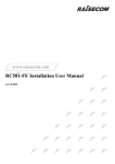
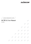
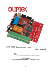
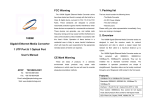
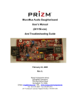
RC511/RC512 Series
SNMP Manageable,
Bandwidth Control,
10/100 Mbps Auto-Sensing
Ethernet Copper to
Fiber Media Converter
User Manual
Beijing Raisecom Science & Technology Co., Ltd
Contents
Chapter 1
RC511/RC512-FE-XX(Rev.A)Series Introduction-------------2
Chapter 2
Connection Configuration -----------------------------------------5
Chapter 3
Installation & Preparation------------------------------------------7
Chapter 4
Switch Setting--------------------------------------------------------8
Chapter 5
Network Management-----------------------------------------------9
1
Chart 1 Introduction
I.
Description:
Article
Description
Number
RC511-FE-M
SNMP Management, Standalone, 10/100Mbps Auto-Sensing, Multi-Mode, 0-2KM,RJ45/DSC
RC511-FE-S1
SNMP Management, Standalone, 10/100Mbps Auto-Sensing, Single Mode, 0-25KM,RJ45/DSC
RC511-FE-S2
SNMP Management, Standalone, 10/100Mbps Auto-Sensing, Single Mode, 10-60KM,RJ45/DSC
RC511-FE-S3
SNMP Management, Standalone, 10/100Mbps Auto-Sensing, Single Mode, 15-120KM,RJ45/DSC
RC512-FE-M
SNMP Management, Host Site Module, 10/100Mbps Auto-Sensing, Single Mode, 0-2KM,RJ45/DSC
RC512-FE-S1
SNMP Management, Host Site Module, 10/100Mbps Auto-Sensing, Single Mode, 0-25KM,RJ45/DSC
RC512-FE-S2
SNMP Management, Host Site Module, 10/100Mbps Auto-Sensing, Single Mode, 10-60KM,RJ45/DSC
RC512-FE-S3
SNMP Management, Host Site Module, 10/100Mbps Auto-Sensing, Single Mode, 15-120KM,RJ45/DSC
Notes:RC512-FE and RC511-FE are always deployed in pairs.
2
II. Product Parameter:
Article
Interface
Wavelength
Number
RC511-FE-M
RC511-FE-S1
RC511-FE-S2
RC511-FE-S3
RC512-FE-M
RC512-FE-S1
RC512-FE-S2
RC512-FE-S3
nm
DSC-RJ45
1310
Supported
Launch
Receiving
Receiving
Power
Sensitivity
Saturation
dBmW
dBmW
dBmW
-18.5~
-31
-14
0~2
3
-35
-3
0~25
0.5
Link
Attenuation
Distance
dB/Km
Km
-14
DSC-RJ45
1310
-13~
-3
DSC-RJ45
-5 ~
1310
-36
-3
10~60
0.5
-37
-3
15~120
0.25
-0
DSC-RJ45
-5 ~
1550/DFB
-0
DSC-RJ45
1310
-18~-
-31
-14
0~2
3
-35
-3
0~25
0.5
14
DSC-RJ45
1310
-13~
-3
DSC-RJ45
-5 ~
1310
-36
-3
10~60
0.5
-37
-3
15~120
0.25
-0
DSC-RJ45
-5 ~
1550/DFB
-0
III. Explanation for the Front Panel and Indicator:
1、The indication on the front panel:
O p tic a l D a ta R e c e iv e R J 4 5 L in k R e c e iv e
a n d T ra n s m it
a n d T ra n s m it
O p tic a l R e c e iv e L in k
RLK
TX
RX
TLK
ACT
LNK
ACT
FDX
COL
RMD 100M
O p tic a l T ra n s m it L in k
R e m o te
M anagem ent
D e v ic e
D u p le x /
C o llis io n
PWR
R a te
Power
2、The Status of Indicators Display:
Indicator
Indicator
Definition
Interface
Name
Optical
Interface
Optical
RLK
Receive Link
Optical
Transmit Link
ON: Optical receive link works in good condition;
OFF: Optical receive link fails.
TLK
ON: Optical transmit link works in good condition;
OFF and RLK ON: Optical transmit link fails.
3
Optical Data
ACT
Flashing: transfer data in the optical interface.
RMD
ON:
Receive and
Transmit Link
Remote
Remote
media
converter
supports
remote
SNMP
Management
management;
Device
OFF: Remote media converter can’t support remote SNMP
management.
RJ45
Duplex/
FDX/CO
ON: RJ45 works at full duplex;
Collision
L
OFF: RJ45 works at half duplex;
FLASH: Half duplex and collision.
RJ45 Link
LNK/AC
ON: RJ45 works in normal conditions;
Receive and
T
OFF: RJ45 link fails;
Transmit
FLASH: transfer data in RJ45.
Rate
100M
ON: Rate is 100M;OFF: Rate is 10M.
Power
PWR
ON: Power is in normal conditions;
Power
OFF: Power occurs error.
3、16 Slots Chassis Front Panel Indication:
PWR
PS1
PS2
5V 12V
5V 12V
RAISECOM
The working conditions displayed by each indicator are as follows:
PWR:usually ON, Power supply of chassis is working in good conditions.
PS1-5V:usually OFF, the PS1 to supply power to modules is in good conditions.
PS1-12V:usually OFF, the PS1 to supply power to fan is in good conditions.
PS2-5V:usually OFF, the PS2 to supply power to modules is in good conditions.
PS2-12V:usually OFF, the PS2 to supply power to fan is in good conditions.
4
Chapter 2
I.
Connection Configuration
Equipment Interconnection
When connecting other equipments, it is required to comply with the specific connecting article numbers
according to the following table. Otherwise, link faults or abnormal data transmission will occur.
Host Site
II.
Remote Site
RC512-FE-M
RC511-FE-M
RC512-FE-S1
RC511-FE-S1
RC512-FE-S2
RC511-FE-S2
RC512-FE-S3
RC511-FE-S3
Connected with Other Equipment (RJ45)
1. RC512/511 series copper to fiber media converters have the function of “auto MDI/MDIX crossover
auto-negotiation”, so both MDI and MDIX crossover can be used to connect with other equipment.
Media Converter
Other Equipment
Connection Mode of RJ45
Media Converter
Switch
Direct/Crossover connected
Media Converter
HUB
Direct/Crossover connected
Media Converter
Router
Crossover/ Direct connected
Media Converter
Network Interface Card
Crossover/ Direct connected
2. When RJ45 interface of RC512/511 seeries media converters works on the forced status, the “auto MDI/MDIX
crossover” function may fail. So it is advised to adopt the following connection modes on the forced status.
Media Converter
Other Equipment
Connection Mode of
RJ45
Media Converter
Switch
Direct Connected
Media Converter
HUB
Direct Connected
5
III.
Media Converter
Router
Crossover Connected
Media Converter
Network Interface Card
Crossover Connected
Duplex Configuration (RJ45)
1.
RC511/2 Series RJ45 Duplex Auto-negotiation:
The copper port/RJ45 of other network equipments must be configured to “auto-negotiation” to ensure
normal data transmission. If other equipments are in forced status, the rate of media converter can remain the
same. But duplex mode shall be fixed in “full duplex status”.
2.
RC511/2 Series RJ45 Force Status
The RJ45 duplex mode of other network equipment must have the same configuration as the following chart.
So data can be transmitted normally.
IV.
Media Converter
Equipment interconnected
RJ45 Mode
RJ45 Mode
100M/ Full Duplex
100M/ Full Duplex
100M/ Half Duplex
100M/ Half Duplex
10M/ Full Duplex
10M/ Full Duplex
10M/ Half Duplex
10M/ Half Duplex
RC511/2 Series connected with Other Equipment (Optical Interface)
Several mandatory conditions:
1、Same wavelength(not including single strand dual wavelength media converter)
2、Same rate
3、Matched Power
4、Fast Ethernet protocol(IEEE 802.3u FastEthernet)
Note: when RJ45 of RC511/2 series media converter connect with other equipment, remote SNMP
management doesn’t work.
6
Chapter 3
I.
Installation and Preparation
Confirm Fiber is Matching with the Media Converter:
RC511/2-FE-M series should adopt multi-mode fiber, and connector of multi-mode fiber should be SC/PC.
RC511/2-FE-S1/2/3 should adopt single-mode fiber, and connector of single-mode fiber should be SC/PC.
II.
Type of fiber wire cable:
The type of fiber cable for multi-mode fiber port: 62.5/125um multi-mode fiber or 50/125um multi-mode
fiber.
The type of fiber cable for single-mode fiber port: 9/125um single-mode fiber.
III.
RJ45 Interface:
CAT 5 of twisted-pair. And the length of twisted-pair wires shall not be more than 100 meters. For connection
configuration, please see Chapter 2 《II. Other Equipment Interconnection (RJ45) 》.
IV.
Installation of Chassis:
19" Standard Chassis
Frame
The fixing accessories of chassis are in the accessory box. If fixing the
chassis with the rear hole, there’ll be 3 cm more space between the front
edge of chassis and the rack; if fixing with the front hole, there’ll be 3cm
less space.
V.
Installation of DC Power Supply:
DC power supply provides three connecters: –48V, ground and 0V. These three
connecters are connected respectively with –48V power cable, ground
protection and 0V power cable.
VI.
Operation Environment Requirements:
-48V 地 0V
Temperature:-20-60℃
Humidity:5%~90% no condensing.
7
VII.
Power Requirements:
1 Slot Chassis: 220V/50Hz AC or –48V DC
16 Slots Chassis: 220V/50Hz AC or –48V DC
VIII.
Dimension:
1 Slot Chassis: 155(width)x 39(height)x 120mm(depth)
16 Slots Chassis: 440(width)x 131(height)x 410mm(depth)
Chapter 4
I.
Switch Setting
SW20 switch setting:
RC512-FE-XX has a 8-place SW20 switch and the functions are as follows in sequence:auto-negotiation
enable/disable, rate 100M/10M, full duplex/half duplex, reserve, frame length 1916 bytes/1536 bytes, remote
network management enable/disable, reserve, failure transfer disable/enable.
Switch
1
Contents
Status
RJ45 auto-sensing or ON
manual setting
OFF
OFF
RJ45 manual setting: rate is 100M
3
RJ45 manual setting: ON
Full Duplex/Half
OFF
Duplex
6
7
8
RJ45 is configured as auto sensing
RJ45 manual setting: rate is 10M
RJ45 manual setting
100M/10M
5
RJ45 is configured as manual setting
ON
2
4
Setting Details
RJ45 manual setting: Half duplex
RJ45 manual setting: Full duplex
Reserve
Over-sized frame
configuration
ON
Over-sized frame up to 1536 bytes
OFF
Over-sized frame up to 1916 bytes
Remote network
management
enable/disable
ON
Disable remote network management
OFF
Enable remote network management
Reserve
Failure transfer
disable/enable
ON
OFF
Enable failure transfer: no receive signal in local
optical link and opposite optical link. Turn off local
RJ45 when it’s no connection with opposite RJ45
link.
Disable failure transfer: Local RJ45 is in normal
conditions.
8
Note: When switch SW20-1 is OFF,switch20-2 and 20-3 is in failure.
II.
SW21 switch setting:
Switch SW21 is used for configuration module:
I.
SW21-1
SW21-2
Module Types
ON
ON
RC511/2-FE(A)-M
OFF
ON
RC511/2-FE(A)-S1
ON
OFF
RC511/2-FE(A)-S2
OFF
OFF
RC511/2-FE(A)-S3
Chapter 5
Network Management
Card/Module Information Review:
With network management software, the status of RC512/511 series at the host site can be reviewed, and
controlled/configured. The status information on “Show Card” is as follows:
No.
Status Title/Control/
Items
Features
Configure
1
Module type
M、S1、S2、S3
Uncontrollable, unconfigurable
2
Failure transfer
Enable/disable
Configurable
3
Remote network management
(Only used for RC512)
Enable/disable
Configurable
4
Loop back control
(Only used for RC512)
Perform/No perform
Controllable
5
Loop back results
(Only used for RC512)
Success/failure
Uncontrollable, unconfigurable
6
Frame length
1916Byte、1536Byte
Configurable
7
Receive rate(Only used for
RC512)
N ×32kb/s
N Configurable
8
Transmit rate(Only used for
N ×32kb/s
RC512)
N Configurable
9
Module voltage beyond upper
limitation ( Only used for
RC511)
Uncontrollable, unconfigurable
Normal/beyond upper
limitation
9
10
Module voltage beyond lower
limitation(Only used for
RC511)
Normal/beyond
limitation
11
Module temperature ( Only
used for RC511)
Actual temperature
Uncontrollable, non-configurable
12
RJ45: Link status
Up、Down
Uncontrollable, non-configurable
13
RJ45: auto-negotiation
Enable/manual
Configurable
14
RJ45: control
Turn on/off
Configurable
15
RJ45: duplex status
Full/half duplex
Configurable
16
RJ45: rate
10M、100M
Configurable
17
Optical Interface: transmit
Link
Up、Down
Uncontrollable, non-configurable
18
Optical Interface: receive Link
Up、Down
Uncontrollable, non-configurable
19
Optical Interface: control
Turn on/off
Uncontrollable, non-configurable
20
Optical Interface: signal
Normal/abnormal
Uncontrollable, non-configurable
II.
lower
Uncontrollable, non-configurable
Show Card Info. Configuration:
Such functions as receiving rate, transmitting rate and RJ45 port, etc, can be configured through “Configure
Card”.
III.
Loop back test:
Modules in host site can be carried out the test of loop back enable/disable through the command ”Show
Card Info. Loop Back”. The results of test can be shown through Show Card Info.
IV.
Show Card Info. Reset:
Host/remote site module can be reset through “Host Show Card Info. Reset” or “Remote Show Card Info.
Reset ”. The frame length of the reset module is 1916 bytes, RJ45 enabled and auto-negotiation mode.
10
BROADBAND
to RAISECOM
Copyright Declaration: Beijing Raisecom Science & Technology Co., Ltd. is the owner of this manual booklet.
The part or whole of this manual are not allowed to use it without Raisecom’s permission.
All rights Reserved.
Address:
th
Tel: 86-10-82884499
229, 4 North Loop Middle Road
Fax:86-10-82885200
1120, Haitai Tower
E-mail:[email protected]
Post Code:100083
Website:www.raisecom.com