1
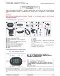
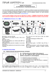
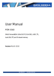
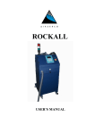
LITE TIRE PRESSURE MONITORING SYSTEM TIRE WATCH TM FOR MOTORCYCLE USER MANUAL Thank you for purchasing this TIRE WATCH TM system. TIRE WATCH will allow you to drive with more confidence and be alerted in the event of a slow leak or puncture. The setup options for the TIRE WATCH TM system are detailed below. For first time use, follow the instructions below. You may not set the system values as detailed in section (C) until the following sensor allocation is completed. A: FIRST USE OF THE DISPLAY FIG 9 – MENU 06 : FRONT & REAR TIRE IDENTIFIER (ID) ALLOCATION The first time the display is powered up, it has to verify the unique ID of the front and rear tire (the unique ID’s are preprogrammed during manufacture - not allocated to a position - and have to be confirmed now to the display). Turn ON the display short push on Bt1 or Bt2 ID symbols are blinking - Drive faster than 20 Mph until Pressure value displayed (time out 4mn ) To invert the front and rear wheel unit sensor allocation FIG 8 – MENU 05 – VALUE INVERSION If this learning phase fails dashes will be displayed instead pressure values. Then you will have to start again the ID confirmation process Switch off the display and wait 8 minutes, motorcycle stopped, before repeating this phase If the pressure values are not displayed after several trials, please contact your dealer. B- KNOW EVERYTHING ABOUT YOUR EQUIPMENT FIG 1 – DISPLAY BUTTON FUNCTIONS : ON / Scrolling menus/ Validation / Backlight only ON / OFF / Display Units Setting / Swap from Pressure to Temperature + backlight (4 seconds) Bt1 Bt2 – Tire Pressure or Temperature information – Pressure (bar/PSI) or Temperature unit (°C) – External temperature - NB : Due to the waterproof nature of the housing, stabilisation of the temperature reading may take several minutes. - 24 Hour Clock Bt .simultaneously. Do the Bt and Note : Permanent back light function : to activate the permanent back light press same to turn off the permanent back light. The permanent use of the back light uses excessive battery life so its usage is recommended at night only. 1 COPYRIGHTS LDL TECHNOLOGY – JULY 2009 1/7 2 LITE TIRE PRESSURE MONITORING SYSTEM C – KIT COMPOSITION ( 8,5 - 11,5) 1 display + button battery CR2450 2 wheel unit sensors (with 11.5XL nut and spring) 2 valves 2 specific seals for some BMW rims (see specificities) 2 seals for 8,5mm valve hole 2 nuts for 8.5mm valve hole (see specificities) 1 peg for valve in spoke (see specificities) 1 connector position assurance (CPA) 1 clipbar 1 clipbody 11 1 bracelet11 12 1 handle bar screws kit : 1 M5x20 screw, 1M5 self locking nut, 1 sleeve 13 1 motor body screw kit : 2 M3 screws, 2 M3 nuts, 2 washers 14 1 steering column screw kit : 1 compressible brace, 1 M5x40 screw, 1 M5 nut with washer FIG 2 – TURN THE DISPLAY ON AND OFF ON : short push on Bt or Bt (temperature displayed after 10s) – The display is waiting for Ids reception 1 2 OFF : long push on Bt or automatically turn off after 6mn caused by no wheel unit sensor transmission 2 FIG 3 – CHANGING THE DISPLAYED MODE Pressure is the standard display mode – To display Temperature short push on Bt To return to the pressure display push again shortly on Bt 2 2 COPYRIGHTS LDL TECHNOLOGY – JULY 2009 2/7 LITE TIRE PRESSURE MONITORING SYSTEM C – SET YOUR VALUES & ALARM SETTINGS Proceed to the scrolling menu > long push on Bt 1 Once the wanted menu is reached (the first digit is blinking to inform you that you enter the menu), to set the 1st digit short push on Bt 2 until the wanted value is reached. To validate the 1st digit and set the 2nd digit short push on Bt 1 Repeat the operation until the last digit. To validate the last digit and the on going menu short push on Bt 1 To accede on the following menu short push on Bt 1 To go back to the standard mode : (FIG 3) long push on Bt 1 D - SET YOUR VALUES BY USING THE UNROLLING MENU FIG 4 – MENU 01 : HOUR SETTING Adjust your values as described in chapter C FIG 5 – MENU 02 : PRESSURE UNIT CHOICE Standard unit is Bar, to swap in PSI Short push on again to bar unit, press again on Bt To validate your unit choice, press on Bt To access the next menu Bt Note : Temperature unit is fixed to °C Bt2 , to swap 2 1 1 FIG 6 – MENU 03 : FRONT & REAR LOW TIRE PRESSURE THRESHOLD SETTING Setting range for front values : 1,4 bar to 3,5 bar (20 to 51 PSI) Minimum alert pressure: Pmin (LO) pre-programmed at 1,8 bar (26 PSI) Set the Pmin (LO) values for front tire. FIG 7 – MENU 04 : REAR LOW TIRE PRESSURE THRESHOLD SETTING Setting range for rear values : 1,4 bar to 3,5 bar (20 to 51 PSI) Minimum alert pressure: Pmin (LO) pre-programmed at 1,8 bar (26 PSI) Set the Pmin (LO) values for rear tire. COPYRIGHTS LDL TECHNOLOGY – JULY 2009 3/7 LITE TIRE PRESSURE MONITORING SYSTEM FIG 8 – MENU 05 – VALUE INVERSION In case of values inversion during the learning phase, (in general front pressure is the lowest value), you can invert them. Reach FIG 7 by an extended push on Bt - Then, push shortly on Bt To validate short push on Bt 2 1 1 E – ALLOCATE YOUR WHEEL UNIT SENSORS Process to follow when you change one or two wheel unit sensors OR when the first learning phase has failed FIG 9 – MENU 06 : ID RECOGNITION During all the learning process, tires must at least be inflated at 1 bar. From ON extended push on Bt until FIG 8 is reached. To launch ID learning short push on Bt ; ID symbols are blinking Drive faster than 20 Mph until Pressure values are displayed (time out 4mn ) 1 2 F – RECOGNIZE THE DIFFERENT ALERT MODES FIG 10 – PRESSURE THRESHOLD CROSSING ALERT When the display receives lower pressure information compared to the programmed thresholds (Pmin), the alert starts: - during the first 3 minutes led blinks in alternance with bar symbol / arrow of the faulty tire- then bar and arrow symbol will flash until new tire inflation (backlight on during 3 minutes to see the alert at night drivings) To display tire temperature during alert short push on Bt - The display will return automatically to pressure alert after 10 seconds 2 FIG 11 – TEMPERATURE THRESHOLD CROSSING ALERT A high temperature threshold is programmed at 80°C for front tire and 90°C for rear tire and cannot be changed. Bt When the display receives upper pressure information compared to the programmed thresholds, the alert starts: - °C symbol / arrow of the faulty tire are flashing until the tire comes to a lower value than the programmed threshold To display tire pressure during alert short push on - The display will return automatically to temperature alert after 10 seconds 2 Note : Pressure alert has priority even if temperature alert is active COPYRIGHTS LDL TECHNOLOGY – JULY 2009 4/7 LITE TIRE PRESSURE MONITORING SYSTEM FIG 12 – LOW BATTERY DISPLAY ALERT Battery symbol is blinking to inform you that you have to change the battery of the display (PANASONIC OR MAXELL CR2450 only) FIG 13 - NON PERMANENT LOSS OF COMMUNICATION In case the receiver does not receive the RF frames sent by the sensors, dashes will be displayed instead of pressure / temperature value. If the problem is permanent, please contact your distributor. FIG 14 – WHEEL UNIT SENSOR LOW BATTERY ALERT The pressure information blinks alternately with Lo symbol to inform you that the sensor must be replaced. Ask your distributor. Note : In winter conditions do not care about this message below 8°C (external temperature) . G – HOW TO FIX YOUR DISPLAY FIG 15 – HANDLE BAR FIXING Put the display to the selected place on the handle bar and fix it with the screw kit n°12. Then clip the display and place the CPA n°8. The tab that allows you to remove the display is now blocked. COPYRIGHTS LDL TECHNOLOGY – JULY 2009 5/7 LITE TIRE PRESSURE MONITORING SYSTEM FIG 16 – BODY MOTOR FIXING First, drill the body and fix the base clipbody base with the screw kit n°13. Then clip the display and place the CPA n°8. The tab that allows you to remove the display is now blocked. FIG 17 – BRACELET FIXING Make the bracelet run through the planned slots of the clipboby (horizontally or vertically) by introducing it from an angle. Then, pull it strongly by using pliers. Clip the display. Do not put the CPA with bracelet. FIG 18 – STEERING COLUMN FIXING (from 12 to 16mm) Insert the screw into the clipbody central hole (screw kit n°14). Then place the compressible brace and the nut on the screw and put it on the steering column tube. Screw until the clipbody is correctly fixed (NB : do not exceed 2Nm). Put in place the CPA n°8 COPYRIGHTS LDL TECHNOLOGY – JULY 2009 6/7 LITE TIRE PRESSURE MONITORING SYSTEM FIG 19 – CHANGE THE BATTERY FROM THE DISPLAY Unscrew the battery cover situated on the back of the display using a five euros cents coin. Replace the used battery with a new one (CR2450 PANASONIC or MAXELL only) as illustrated and screw again the battery cover. Please check that the seal is correctly in place. FIG 20 – REMINDER FOR MOTOR DEALERSHIP FOR WHEEL UNIT SENSORS MOUNTING Screw the nut with a 5mm allen key. Do not exceed 2 rounds per second and hold the valve while screwing to prevent it from turning around. Final torque 4,2Nm +/- 0,2Nm – The sensor must not get in touch with the tire during the mounting process. H – SAFETY AND GENERAL INFORMATION Users are not permitted to proceed any changes or modify the device in any way. TIRE WATCH TM has an information goal that does not replace the inflation phases under the initiative and entire responsibility of the pilot. Tire pressure has to be done according to manufacturer recommendations; always inflate your tire cold (23°C). If the inflation process takes less than 6 min (after driving), the information will be updated every 5 seconds. Should the opposite occur, the information will be updated while driving. USA, Canada and European Union Directives Conformity Products marked CE are in compliance with Directive R&TTE (99/5/EC). Products marked FCC are in compliance with Directive FCC- part 15. Using precautions - Never fix directly on a metal part, you may loose signal. - Do not wash directly with a jet of water (ex : karcher). TIRE WATCH is only rain proof - Avoid prolonged sun exposition when you don’t use it. - Do not repair the device by your own, you may loose warranty. The internal components reparation must be done by qualified technician or recognized repairing centre. - Never use solvent, only wash TIRE WATCH with water soap and sweet cloth. - If you drive close to electromagnetic disturbance (military base, embassy,…) you may loose temporary the signal. Warranty : one year by presenting your bill and the warranty card filled out and stamped by your motor dealership. LDL Technology reserves the right to modify its product and to bring any modification without preliminary notice. COPYRIGHTS LDL TECHNOLOGY – JULY 2009 7/7