1
®
WIRELESS PASSIVE INFRARED
DETECTOR APD-100
apd100_en 08/08
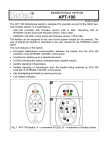
The APD-100 wireless passive infrared detector is designed for operation as part of the ABAX two-way wireless
system. The signal from pyroelement is processed digitally. The detector is characterized by a high interference
immunity. Operating parameters of the detector (sensitivity and in the detector with firmware version 2.01
enabling/disabling the option of immunity to animals up to 15 kg in weight) are programmable by radio.
Note: The APD-100 detector with firmware version 2.01, is supported by the ACU-100 controller with firmware
version 1.07 or later (it cannot be registered in the controllers having older versions of firmware).
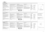
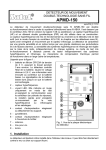
Explanations for Fig. 1:
1 - CR123A 3 V lithium battery, ensuring operation for
approx. 3-year period. The detector controls the battery
status. When the voltage drops to 2.6 V, the "low
battery" information is sent to the controller. The low
battery signaling continues until the battery is replaced.
2 - antenna.
3 - LED indicator. It lights red in the test mode only,
indicating communication with the controller (during
polling), violations and tampers.
4 - pyroelement.
5 - tamper contact, which responds to opening of the
housing.
6 - tamper contact, which responds to pull-off from the
back tamper unit.
7 - positioning scale.
8 - fixing screw hole.
9 - screen.
Fig. 1. View of the detector PCB.
1. INSTALLATION
Before mounting the detector permanently, check the level of signal received from the detector
by the ACU-100 controller and, if necessary, change the place of installation so that the location
is optimal in terms of communication.
Install the battery inside the detector just before registering it in the controller. If unregistered or
having no communication with the controller, the detector will consume more energy, which will
reduce the battery life.
It is advisable to be particularly careful during installation so as not to foul up or damage the
pyroelement.
In APD-100 with firmware version 2.01, if the pet immunity option is to be enabled, the detector
cannot be mounted on the holder.
1. Open the housing.
2. Install the battery and add the detector to the wireless system (see the ACU-100 controller user manual).
A label with 7-digit serial number that should be entered during registration of the detector in the system is
provided on the screen on the electronics board.
3. Select the place where the detector is to be installed and attach it there temporarily.
4. Check the level of signal reaching the controller from the detector. If necessary, select another place for
installation.
5. Having selected the place which ensures the optimum signal level, remove the electronics board from
the housing.
6. Attach the back tamper unit directly to the wall or to the holder screwed down to the wall or ceiling
(see Fig. 2).
7. Fasten the rear part of the housing to the back tamper unit (see Fig. 2).
2
SATEL
APD-100
8. Install the electronics board in the housing. If the detector is to be installed at a height of 2,4 m, set
the board so that the central mark of scale coincides with the indicator placed on the housing. Such
a setting will ensure that the manufacturer specified lens range is obtained. Otherwise, you should adjust
the pyroelement setting by moving the board up (if the detector is installed higher than 2,4 m) or down (if the
detector is installed lower than 2,4 m) as against its central position.
A
B
Fig. 2. Detector mounting methods. A – mounting directly to the wall (required, if the pet immunity option is to be
enabled). B – mounting on the holder. 1 – holder. 2 – back tamper unit. 3 – screw fixing the back tamper unit to
the holder. 4 – screws fixing the back tamper unit to the wall. 5 – rear part of detector housing. 6 – screw fixing
the rear part of detector housing to the back tamper unit.
9. Close the housing.
10. Configure the detector as required. Information on configuration – see the ACU-100 controller user manual.
11. Launch remotely the test mode and check that movement within the monitored area will make the LED
indicator light red. If necessary, change the detector sensitivity.
12. Quit the test mode. The detector is now ready for work.
2. LENSES
WP type lens is mounted in the APD-100 detector with firmware version 2.01. Only this type of lens guarantees
correct functioning of the pet immunity option. If another type of lens is mounted, enabling the pet immunity
option is not recommended.
In the APD-100 detector with firmware version prior to 2.01 the extra-wide lens (EWA) is installed, however it
can be replaced with another one, having different characteristics (range, number of beams, angle of view).
Lenses are available with the following specifications:
It.
1
2
3
Lens type
extra wide angle
long range with access zone
monitoring
vertical barrier
Range
15 m
141,2°
Angle of view
30 m
main beam – 3 m wide (at the end of range)
22,5 m
2.2 m wide (at the end of range)
APD-100
3
ABAX
10 m
5m
88,5º
5m
10 m
2,4 m
2 m 4,5 m
8,7 m
17 m
Fig. 3. Distribution of beams and range of the detector with WP type lens.
Note: The detector operating range should be selected to match the size of space where the detector is to be
installed. The size of the space along the main direction of detector positioning is not to be less than 1/3
the nominal range of the detector. Improper selection of the lens may cause excessive sensitivity and
trip false alarms.
3. TECHNICAL DATA
Operating band frequency ..................................................................................................868.0 MHz ÷ 868.6 MHz
Radio communication range ........................................................................................... up to 150 m (in open area)
Supply ........................................................................................................................... lithium battery CR123A, 3 V
Battery life .........................................................................................................................................approx. 3 years
Environment class ...................................................................................................................................................II
Operating temperature range ........................................................................................................... -10 °C...+55 °C
Detectable movement speed................................................................................................................... 0,3 ÷ 3 m/s
Housing dimensions ....................................................................................................................... 63 x 96 x 49 mm
Recommended height of installation ................................................................................................................2,4 m
Weight...............................................................................................................................................................108 g
Batteries in the battery-supplied wireless equipment should be replaced by qualified personnel.
Incorrect replacement of the battery can pose an explosion hazard.
Always use the CR123A 3 V lithium batteries.
The used batteries must not be discarded, but should be disposed of in accordance with the
existing rules for environment protection.
4
SATEL
APD-100
19,4°
10m
5m
0
5m
10m
2,4m
1,7m
4,6m
7,7m
15,3m
Fig. 3. Distribution of beams and operating range of detector with extra wide angle (EWA) lens.
1471
DECLARATION OF CONFORMITY
SATEL spółka z o.o.
ul. Schuberta 79
Product:
80-172 Gdańsk, POLAND
APD-100 – Wireless PIR Detector for ABAX System
tel. (+48 58) 320-94-00
fax. (+48 58) 320-94-01
Product description: Wireless movement detector of PIR type, designed for interaction with elements of the
ABAX wireless system, operating in the 868.0MHz – 868.6MHz frequency band, supplied from a 3 V lithium cell.
The device is intended to be used in burglary and panic alarm systems.
This product conforms to the following EU Directives:
R&TTE 1999/5/EC
This product meets requirements of the harmonized standards:
R&TTE: ETSI EN 300 220-1: v.1.3.1; ETSI EN 300 220-3: v.1.1.1;
EMC: ETSI EN 301 489-1: v.1.5.1.; EN 301 489-3: v.1.4.1
Safety: EN60950-1:2001
Notified body taking part in conformity evaluation:
Identification No.: 1471
Head of Test Laboratory:
Gdańsk, Poland 2005-07-15
Michał Konarski
The latest EC declaration of conformity and product approval certificates are available for downloading on our
website www.satel.pl
Manufacturer: