1
Application Note
AN-1025
FIFO CONFIGURATION
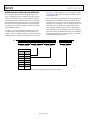
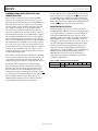
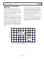
Configuration of the FIFO is done through the FIFO_CTL
register. Through the FIFO_CTL register, the mode of operation
for the FIFO is determined and configured by the FIFO_MODE
bits. The trigger interrupt for trigger mode is also configured in
the FIFO_CTL register as well as the samples bits, which operate
differently depending on the selected mode.
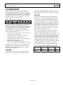
Table 2. FIFO_CTL Register (Read/Write)
D7
D6
FIFO_MODE
D5
Trigger
D4
D3
D2
D1
Samples
D0
To prevent the generation of false interrupts or the unintentional filling of the FIFO, configure the FIFO and the triggering
interrupt(s) for trigger mode or watermark before enabling any
corresponding interrupts and before placing the part into
measurement mode. As a general rule, configure the digital
accelerometers in the following order:
1.
2.
3.
4.
5.
Set data parameters such as data rate, measurement range,
data format, and offset adjustment.
Configure interrupts (do not enable): thresholds and
timing values, and map interrupts to pins.
Configure FIFO (if in use): mode, trigger interrupt if using
trigger mode, and samples bits.
Enable interrupts: INT_ENABLE register.
Place part into measurement mode: POWER_CTL register.
Following this order prevents false watermark interrupts when
the FIFO is empty and the samples bits are configured to its
default value of 0, as well as false interrupts due to interrupts
being enabled with default values.
FIFO MODES
The FIFO has four modes of operation: bypass mode, FIFO
mode, stream mode, and trigger mode. Each mode is confi-
gured through the FIFO_MODE bits in the FIFO_CTL register.
Refer to the ADXL345 data sheet for which values correspond
to which mode.
Bypass Mode
In bypass mode, the FIFO is effectively disabled. Each time
a new sample is ready at the output filter, the value stored in
the data registers or FIFO[0] is immediately replaced by the
new data. If the data registers are read again before new data is
ready, the old data remains until a new sample is available and
then immediately replaces the old data in FIFO[0] or the data
registers. If the current sample of data is being read when new
data is available, a double-buffered output allows the read to
finish first and then places the new data into the output filter,
preventing the loss of data due to a read.
In this mode, the DATA_READY interrupt is normally used
to signal to the master device that new data is ready to be
retrieved. The DATA_READY interrupt is configured by configuring the DATA_READY bit in the INT_MAP register to the
interrupt pin of choice and then setting the DATA_READY bit in
the INT_ENABLE register. The interrupt that DATA_READY
is mapped to triggers when new data is available and is cleared
by reading the data in the data registers. The polarity of the
DATA_READY interrupt is active high by default. DATA_READY
and all other interrupts can be configured to active low by
setting the INT_INVERT bit in the DATA_FORMAT register.
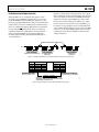
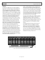
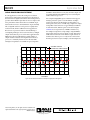
Table 3. INT_MAP/INT_ENABLE Registers (Read/Write)
D7
DATA_READY
D3
Inactivity
Rev. 0 | Page 7 of 12
D6
SINGLE_TAP
D2
FREE_FALL
D5
DOUBLE_TAP
D1
Watermark
D4
Activity
D0
Overrun