1
Instrumentation &
Control Panel
Submittal
HSI1102-0-0-1
Blower Panel
P.O. # 119729
Houston Service Industries
October 2008
2530 Shell Road
Georgetown, TX 78628
Phone: (512) 863-3224
Fax: (512) 868-5446
www.controlpanelsusa.net
CP USA Job #08-3751
CP USA Project Manager: Joe Kornele
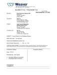
Houston Service
Industries
October 2008
CP USA
Job # 08-3751
P.O. # 119729
HSI1102-0-0-1
SCHEDULE OF EQUIPMENT
ITEM #
7
DESCRIPTION
Control Panel
Enclosure, Type 4, Wall mount, with
quarter turn latches
Back Panel
Circuit Breaker, 5 Amp, 1 Pole, UL489
Surge Suppressor, 120VAC, 2.5Amp,
filtering, 45KA, 10 yr warranty
Power Supply, 24V, 0.6A, Current
Limmiting, Short Circuit & Overload
protection built in
PLC Processor, Micrologix, 120VAC, 14
AC Inputs, 10 Relay Outputs, 2 port
Analog Input Module, 4 Point
8
Ethernet Adapter Communication Module
1
2
3
4
5
6
9
10
11
12
13
14
15
16
17
18
19
20
Micrologix Cable, 8 pin Mini Din to 8 pin
Mini Din, 6.5 feet
2 Line Text Display
Communication Cable between Processor
& Touchscreen
Relay, DPDT, 10A
Relay Base, 4-pole
Pilot Light, 30mm, Nema 4X, LED, Full
Voltage, Red
Pushbutton, Momentary, Black, 30mm,
Heavy Duty Nema 4X, 1 NO Nema rated
Contact
Current Transducer, 4-20mA, 0-50, 0-100,
0-200 Amps
Typical Equipment on Each Panel
Terminal Block, Feed Through, Finger
Safe, 26-10awg, 41 Amp, 800Volt, Type
UT4
Ground Terminal Block, Finger Safe, 2610awg, 41 Amp, 800Volt, Type UT4-PE
Ground Bus Bar
Wire Way
Prepared by Control Panels USA Inc.
MANUFACTURER
PART NUMBER
QUANTITY
UNIT
Saginaw
SCE-24EL2008LP
1
each
Saginaw
Siemens
SCE-24P20
5SJ41111-7HG40
1
1
each
each
Control Concepts
IC+102
1
each
Sola
SDP06-24-100T
1
each
Allen-Bradley
1762-L24AWA
1
each
Allen-Bradley
1762-IF4
1
each
Allen-Bradley
1761-NET-ENI
1
each
Allen-Bradley
1761-CBL-HM02
1
each
EZ Automation / AVG
EZ-220
1
each
EZ Automation / AVG
EZ-MLOGIX-CBL
1
each
Finder
Finder
55.32.8.120.0030
94.04
1
1
each
each
C3 Controls
FVLU120LR-PLLRD
2
each
C3 Controls
PBO-FCBK-NO
1
each
Veris
H721HC
1
each
Phoenix Contact
3044102
A/R
each
Phoenix Contact
3044128
A/R
each
Square D
IBOCO
PK Series
T1 Series
A/R
A/R
each
ft
Page 1 of 1
10/13/2008
Part Information - SCE-24EL2008LP
Part Details - SCE-24EL2008LP
Part Number: SCE-24EL2008LP
Description: EL Enclosure
Height: 24.00 inches
Width: 20.00 inches
Depth: 8.00 inches
Page Number: 157
List Price: $275.56
Panel: SCE-24P20 Product Code: E3
Est. Shipweight: 35.00 lbs.
NEMA Rating: 12 & 4
Construction 0.075 In. carbon steel.
Seams continuously welded and ground smooth.
● Flange trough collar around all sides of door
opening.
● Oil-resistant gasket.
● Collar studs provided for mounting optional
panels.
● Concealed hinge.
● Removable and interchangeable doors.
● Black quarter turn latches on three sides of the
doors.
● Latches are opened or closed with a screwdriver.
● Mounting holes in back of enclosure.
● Mounting hardware, sealing washer and hole
plug included.
● Removable print pocket.
● Ground studs on door and body.
●
●
Similar Partnumbers ●
●
●
●
●
●
●
●
●
●
●
●
●
●
SCE-12EL1206LP
SCE-12EL2406LP
SCE-16EL1206LP
SCE-16EL1208LP
SCE-16EL1408LP
SCE-16EL1606LP
SCE-16EL1608LP
SCE-16EL2006LP
SCE-16EL2008LP
SCE-20EL1206LP
SCE-20EL1606LP
SCE-20EL1608LP
SCE-20EL1612LP
SCE-20EL2006LP
http://www.saginawcontrol.com/part_info.php?value=1&PartNum=SCE-24EL2008LP (1 of 2)3/22/2007 4:29:44 AM
Printable Version
Detailed Drawing (PDF)
Downloadable Drawing
3D STP Drawing (NEW!)
Having trouble downloading
drawings? Click Here for help.
Application Designed to house electrical and
electronic controls, instruments and
components. Provides protection
from dust, oil and water. For outdoor
application a drip shield is
recommended.
Finish ANSI-61 gray urethane polyester
powder coating inside and out over
phosphatized surfaces. Stainless
steel enclosures are Type 304
stainless with #4 brushed finish.
Optional panels are powder coated
white epoxy polyester.
Options - Optional Tamper-resistant inserts
are available.
- Optional mounting feet available.
- Door hardware available.
Industry Standards NEMA Type 4, 12, & 13
UL Listed Type 4 & 12
CSA Type 4 & 12
IEC 60529 IP 66
Notes Interchangeable latches and
handles found on pages 147-148.
Part Information - SCE-24P20
Part Details - SCE-24P20
Part Number: SCE-24P20
Description: Subpanel, Bent
Height: 21.00 inches
Width: 17.00 inches
Depth: 0.88 inches
Page Number: 177
List Price: $42.79
Product Code: P3
Est. Shipweight: 11.00 lbs.
NEMA Rating: N/A
Edge Flanges: Four
Configuration: C
Printable Version
Detailed Drawing (PDF)
Downloadable Drawing
3D STP Drawing (NEW!)
Similar Partnumbers ●
●
●
●
●
●
●
●
●
●
●
●
●
●
●
●
●
●
●
●
●
●
●
●
SCE-12DLP12
SCE-12P10
SCE-12P12
SCE-12P24
SCE-14P12
SCE-14P8
SCE-16DLP14
SCE-16P10
SCE-16P12
SCE-16P14
SCE-16P16
SCE-20P12
SCE-20P16
SCE-20P20
SCE-20P20AL
SCE-24P16
SCE-24P24
SCE-30P16
SCE-30P20
SCE-30P24
SCE-30P30
SCE-36P16
SCE-36P24
SCE-36P30
Installation Information -
●
Sub-Plate Layout & Grounding
http://www.saginawcontrol.com/part_info.php?value=1&PartNum=SCE-24P20 (1 of 2)8/31/2006 6:20:31 AM
Having trouble downloading drawings? Click Here for
help.
Finish Powder coated white epoxy polyester.
Options Sub-plates can be special ordered in Stainless Steel or
Galvanized material. Please consult a factory
representative for assistance.
Control Circuit Protection
New 5SJ Branch Circuit Protector
5SJ41 70 mm mounting depth
Features
All new 5SJ41 miniature circuit breakers are designed to comply with UL489 and CSA 22.2 No. 5-02 standards. They are used in single
pole, branch circuit protection applications up to 240 VAC maximum and 60 VDC maximum. Refer to Technical Data (page 16/5) for
additional information.
Selection and ordering data
In
Characteristic B
Order No.
A
List
Price $
Characteristic C
Order No.
1 item
List
Price $
Characteristic D
Order No.
1 item
List
Price $
1 item
1-pole
1
2
0.3
0.5
1
1.6
2
3
4
5
6
8
10
13
15
16
20
25
30
32
35
40
45
50
60
63
16/4
—
—
—
—
—
—
—
—
5SJ4106-6HG40
—
5SJ4110-6HG40
5SJ4113-6HG40
5SJ4118-6HG40
5SJ4116-6HG40
5SJ4120-6HG40
5SJ4125-6HG40
5SJ4130-6HG40
5SJ4132-6HG40
5SJ4135-6HG40
5SJ4140-6HG40
5SJ4145-6HG40
5SJ4150-6HG40
5SJ4160-6HG40
5SJ4163-6HG40
58.00
58.00
58.00
58.00
58.00
58.00
58.00
58.00
58.00
62.00
62.00
64.00
66.00
70.00
70.00
5SJ4114-7HG40
5SJ4105-7HG40
5SJ4101-7HG40
5SJ4115-7HG40
5SJ4102-7HG40
5SJ4103-7HG40
5SJ4104-7HG40
5SJ4111-7HG40
5SJ4106-7HG40
5SJ4108-7HG40
5SJ4110-7HG40
5SJ4113-7HG40
5SJ4118-7HG40
5SJ4116-7HG40
5SJ4120-7HG40
5SJ4125-7HG40
5SJ4130-7HG40
5SJ4132-7HG40
5SJ4135-7HG40
5SJ4140-7HG40
5SJ4145-7HG40
5SJ4150-7HG40
5SJ4160-7HG40
5SJ4163-7HG40
Discount Code: Mini Circuit Breakers
58.00
58.00
58.00
58.00
58.00
58.00
58.00
58.00
58.00
58.00
58.00
58.00
58.00
58.00
58.00
58.00
58.00
58.00
62.00
62.00
64.00
66.00
70.00
70.00
5SJ4114-8HG40
5SJ4105-8HG40
5SJ4101-8HG40
5SJ4115-8HG40
5SJ4102-8HG40
5SJ4103-8HG40
5SJ4104-8HG40
5SJ4111-8HG40
5SJ4106-8HG40
5SJ4108-8HG40
5SJ4110-8HG40
5SJ4113-8HG40
5SJ4118-8HG40
5SJ4116-8HG40
5SJ4120-8HG40
5SJ4125-8HG40
5SJ4130-8HG40
5SJ4132-8HG40
5SJ4135-8HG40
5SJ4140-8HG40
5SJ4145-8HG40
5SJ4150-8HG40
5SJ4160-8HG40
5SJ4163-8HG40
58.00
58.00
58.00
58.00
58.00
58.00
58.00
58.00
58.00
58.00
58.00
58.00
58.00
58.00
58.00
58.00
58.00
58.00
62.00
62.00
64.00
66.00
70.00
70.00
Siemens Energy & Automation, Inc.
Industrial Controls Catalog
Control Circuit Protection
Supplementary Protectors
Dimensions
5SX2 supplementary protectors
5SX2,
5SY4, 5SY5 supplementary protectors
5SJ4, single pole branch circuit protector
5SX9 auxiliary switch, 5SX9 fault signal
Additional component for 5SX2; can be retrofitted 5SX9 1.., 5SX9 2..
5ST3 auxiliary switch
5ST3 fault signal contact
can be retrofitted to 5SY4, 5SY5, 5SP4
5SP4 supplementary protectors
5ST3 shunt trip
5ST3 undervoltage release
can be retrofitted
to 5SY4, 5SY5, 5SP4
Siemens Energy & Automation, Inc.
Industrial Controls Catalog
16/23
Control Circuit Protection
General Data
5SJ4 Branch Circuit Protector
Technical Data
Specification
Tripping characteristic
5SJ41 Mini-Breaker
C
B
Number of poles
1
V AC: 240 max.
Rated voltage (UL 489)
Operating voltage, min.
V DC: 60 max.
24 VAC/DC
Rated current
Interrupting Rating (UL 489)
AC: Max. RMS Symmetrical
Standards
Certifications
Degree of protection
Device depth
Mounting technique
Terminals
Terminal tightening torque
Wire Size
Recommended Wire Strip Length
Mounting
Position
Ambient temperature
Calibration temperature
Storage temperature
Resistance to vibration
Dimensions
Siemens Energy & Automation, Inc.
Industrial Controls Catalog
6 to 63 A
D
0.3 to 63 A
V AC 240: 14 kA
0.3 to 63 A
V AC 240: 14 kA
(0.3 - 40 A)
V AC 240: 5 kA
(0.3 - 20 A)
V AC 240: 5 kA
(45 - 63 A)
V DC 60: 10 kA
(25 - 63 A)
V DC 60: 10 kA
(0.3 - 63 A)
UL 489, CSA 22.2 No. 5-02, IEC/EN 60 898
UL, cUL, File No. E 243414
IP 10 acc. to DIN EN 60 529; IP 40 when panel mounted
70 mm
Standard 35 mm DIN rail
Identical screw terminals on both line and load sides
31 lbs. in. (3.5 Nm)
14-4 AWG (1.5 - 25 mm2)
60/75˚C, Cu only
0.59 in. (15 mm)
(0.3 - 63 A)
V AC 240: 14 kA;
V DC 60: 10 kA
As Required
-13˚ to +113˚F (-25˚ to +45˚C)
temporary: +131˚F (+55˚C); max. humidity: 95%
25˚C (77˚F) acc. to UL 489
30˚C (86˚F) acc. to EN 60 898
-40˚ to +167˚F (-40˚ to +75˚C)
60 m/s2 at 10 Hz up to 150 Hz acc. to IEC 60 068-2-6
see catalog page 16/23
16/5
Control Circuit Protection
General Data
Trip characteristics
Tripping characteristics acc. to EN 60 898
Tripping characteristic B, -6
Type B characteristic designed for European residential circuit protection.
This characteristic can also
be used for protection of
computers and electronic
equipment. Magnetic trip
point - 3 to 5 times In rating.
Thermal trip point - 1.13 to
1.45 protector rating.
Tripping characteristic C, -7
Type C characteristic is for
general device protection in
control circuits. Magnetic
trip point - 5 to10 times In rating. Thermal trip point - 1.13
to 1.45 protector rating.
Tripping characteristic D, -8
Type D characteristic is designed for high inrush loads.
Magnetic trip point - 10 to 20
times In rating. Thermal trip
point - 1.13 to 1.45 protector
rating.
1,13 1,45
120
A I2_06353c
20
10
6
4
1,13 1,45
120
2
1
40
20
2
20
2
Seconds
Seconds
10
6
4
10
6
4
1
0,6
0,4
2
1
0,6
0,4
0,2
0,2
0,1
0,06
0,04
0,1
0,06
0,04
0,02
For different ambient temperatures, the current values of the
delayed tripping operation
change by approximately 5%
per 10°K temperature difference. Specifically they increase
for temperatures below 25°C
(5SJ41), 30°C (5SP, 5SX, 5SY)
and decrease for temperatures
above 25°C (5SJ41), 30°C (5SP,
5SX, 5SY).
20
1
40
10
6
4
0,01
A I2_06354c
60
40
Tripping time
Tripping time
Minutes
60
40
Minutes
Tripping characteristic A, -5
Type A characteristic is designed to protect very sensitive circuits such as
semiconductors. Magnetic
trip point - 2 to 3 times In rating. Thermal trip point - 1.13
to 1.45 protector rating.
0,02
1 1,5 2
3 4 5 6 8 10 15 20
Multiple of rated current
0,01
1
30
If more that one electrical circuit
is loaded in a series of miniature
circuit breakers or supplementary protectors, the resulting increase in ambient temperature
affects the characteristic curve.
In this case an additional correction factor found in the following table must be used.
1,5 2
3 4 5 6 8 10 15 20
Multiple of rated current
Number
1
2-3
4-6
>7
Correction factor K
1.00
0.90
0.88
0.85
30
For DC voltages the maximum
current values of the instantaneous tripping operation increase by a factor of 1.2.
16/2
Siemens Energy & Automation, Inc.
Industrial Controls Catalog
Technical Specification
IC+102
CONNECTION DIAGRAM
The Islatrol Plus is a series connected high-frequency noise filter with transient protection. The
Islatrol Plus units offer the flexibility of either receptacle/line cord connection or hard-wired
connection to critical loads up to 30 Amperes. Applications include industrial or office equipment,
computers placed in harsh environments, etc.
Nominal Operating Voltage
Operating Voltage Range
Operating Frequency Range
Rated Output (Amps)
ANSI/IEEE C62.41 Category
Connection Type
Phase Configuration
Size
Enclosure
Weight
Modes Of Protection
Indication of Suppression Status
Response Time
Operating Temperature
Operating Humidity
Certifications
Warranty
Maximum Continuous Operating Voltage (MCOV)
Line to Neutral
Peak Surge Current Capability (8 x 20 s)
Line to Neutral
Line to Ground
Neutral to Ground
Total
Load Surge Current Rating
10 MSEC
1 SEC
10 SEC
ANSI/IEEE C62.41 Cat A Ringwave (6 kV, 200A, 100 kHz)
Normal Mode
Common Mode
ANSI/IEEE C62.41 Cat B Ringwave (6 kV, 500A, 100 kHz)
Normal Mode
Common Mode
Frequency Response
Normal Mode
Common Mode
IC+102
120 VAC, Single Phase
120 VAC +/- 25%
47 - 63 Hz
2.5 Amperes
Category A & B
Series Connected, Terminals #22 – #12
2 Wire + Gnd
4 x 2.88 x 1.81 (Inches)
High Impact Plastic
1.0 lbs. (0.45 kgs.)
L - N, L - G, N - G
Green LED Power Indication
< .5 ns Normal mode
-40°C TO 45°C
0% TO 95% Non-condensing
UL 1283, CUL, ISO 9001
10 Year
150 VAC
15,000 Amps
15,000 Amps
15,000 Amps
45,000 Amps
5 x Nominal
3 x Nominal
2 x Nominal
1.0 V
302 V
178 V
302 V
60 dB minimum, forward/reverse, 100 kHz to 50 MHz
60 dB minimum, forward/reverse, 5 MHz to 50 MHz
Rev 0 1/27/03
4
Power Supplies
SDP™ Low Power DIN Rail Series
The compact, lightweight DIN Rail power supplies come
in output voltages from 5 to 48 Vdc and power ratings of
up to 100 Watts. These extra small, efficient units are
designed specifically for the industrial environment. Each
unit is rated from -10ºC to 70ºC, with no derating necessary
until above 60ºC.
Many extra “industrial” features are standard for the
SDP PowerBoostTM overload circuitry can start up
industrial loads (i.e. motors, relays, solenoids and DC-DC
converters), that can cause ordinary power supplies to
foldback or shutdown. Each unit contains a DC indicator
and front panel adjustment potentiometer. With the Sola
SDP series, you can count on a high grade design.
UL 508 Listed
IND. CONT.
EQ.E6I379
Features
UL 60950
E137632
CUL/CSA-C22.2
No. 234-M90
EMC and
Low Volt.
Directive
Related Products
• Ultra slim 15W footprint
• SDN™ Series
• No tools required for mounting
• SCP Series
• Adjustable output
• SCL Series
• PowerBoostTM industrial overload design
Applications
• Overvoltage, short circuit protection
• NEC Class 2 Current Limited
• Industrial Control
• Continuous short circuit protection
• Process Control
• Low output noise
• Machine Control
• Screw terminal connections
• Building Automation
• RoHS Compliant
• Instrumentation
• Three year warranty
Selection Table
Catalog Number
DC Output Voltage
Output Current
SDP 5-5-100T
5-6V
5A
SDP 2-12-100T
10 - 12 V
3 - 2.5 A
SDP 3-15-100T
12 - 15 V
4.2 - 3.4 A
SDP 1-48-100T
48 - 56 V
1A
SDP 06-24-100T
0.6 A
SDP 1-24-100T
1.3 A
SDP 2-24-100T
24-28 Vdc
Ripple / Noise
2.95 in x 1.77 in x 3.58 in
(75 mm x 45 mm x 91 mm)
<50 mVpp
2.1 A
SDP 4-24-100LT
3.8 A
SDP 4-24-100RT*
4.2 A
* NEC Class 1
118
Size (H x W x D)
Visit our website at www.solahd.com or
contact Technical Services at (800) 377-4384 with any questions.
2.95 in x 0.9 in x 3.8 in
(75 mm x 22.8 mm x 96.7 mm)
2.95 in x 1.77 in x 3.58 in
(75 mm x 45 mm x 91 mm)
2.95 in x 2.85 in x 3.8 in
(75 mm x 72.5 mm x 96.7 mm)
4
Power Supplies
SDP™ Series Specifications (24 V models)
Description
Catalog Number
SDP 06-24-100T
SDP 1-24-100T
SDP 2-24-100T
SDP 4-24-100LT
SDP 4-24-100RT
Input
85-264 Vac, 90-375 Vdc
Input Voltage1
85-132 / 176-264 Vac, 210-375 Vdc
47-63 Hz
Input Frequency
Input Current
0.4 A / 0.25 A
0.7 A / 0.4 A
1.1 A / 0.7 A
Losses
2.2 A / 1.2 A
> 25 ms
Hold-Up Time
Efficiency
1.8 A / 1.0 A
Not required. Unit provides internal fuse (T3A, not accessible)
External Fusing
> 80% typ.
> 83% typ.
> 86% typ.
> 88% typ.
< 3.75 W typ.
< 6.1 W typ.
< 8.1 W typ.
< 12 W typ.
Output
24 V (22.5 - 28.5 Vdc Adj.)
Output Voltage
24 V (24 - 25.7 Vdc Adj.)
< 50 mVpp
Ripple/Noise2
> 26 Vdc, but < 27.2
Vdc, auto recovery
> 30 Vdc, but < 33 Vdc, auto recovery
Overvoltage Protection (OVP)
Output Noise
Suppression
Rated Continuous
Loading
24 V (22.5 - 28.5 Vdc Adj.)
Static 0.5% Vout, dynamic + 2% Vout overall\
Voltage Regulation
> 30 Vdc, but < 33 Vdc,
auto recovery
Radiated EMI values below EN61000-6-2
0.63 A @ 24 Vdc /
0.54 A @ 28 Vdc
1.3 A @ 24 Vdc /
1.1 A @ 28 Vdc
2.1 A @ 24 Vdc /
1.8 A @ 28 Vdc
3.8 A @ 24.5 Vdc
4.2 A @ 24.5 Vdc /
3.6 A @ 28 Vdc
Continuous operation at overload/short-circuit: up to 1.5 x Nominal Current Continuous
Overload Behavior
Unit is continuously protected against short-circuit, overload and open-circuit.
Protection
35 V
Power Back Immunity
Installation
Status Indicators
Green LED on, when Vout “OK”.
Case & Mounting
Molded plastic housing using UL 94 approved flameproof material rating 94V-2.
Simple snap-on to DIN TS35/7.5 or TS35/15 rail system.
Dimensions
(H x W x D) (in/mm)
2.95 x 0.9 x 3.8
(75 x 22.8 x 96.7)
Weight - lbs (kg)
0.35 lbs (.16 kg)
Mounting Orientation
2.95 x 1.77 x 3.58 (75 x 45 x 91)
2.95 x 2.85 x 3.8
(75 x 72.5 x 96.7)
0.5 lbs (.23 kg)
0.7 lbs (.32 kg)
Standard: Vertical; Optional: Horizontal or on top (Contact Technical Services).
Ventilation/Cooling
•Free space for cooling
Normal convection, no fan required; Above/below: 25 mm recommended.
Connection
•Connector size range
Input: screw terminals, connector size range: 20-12AWG (1.5 - 6 mm2) for solid or stranded conductors.
General
Temperature
MTBF
Humidity
Storage: -25°C...+85°C Operation: -10°...+60°C full power with linear derating to half power from 60°C to 70°C.
(Convection cooling, no forced air required).
> 500,000 hours according to Telcordia/Bellcore Document SR-332, Issue 1.
Up to 90% RH, noncondensing; IEC 68-2-2, 68-2-3
Electromagnetic
Emissions (EME)
EN61000-6-3 (Includes EN61000-6-4) Class B (EN 55022) incl. Annex A
Electromagnetic
Immunity (EMI)
EN61000-6-2 (Includes EN61000-6-1) (EN55024) Criterion A: no derogation of performance
SELV (acc. EN60950)
Safe Low Voltage
Protection Class/Voltage
IP20 (IEC529), Protection Class 1 (IEC536)
3 years
Warranty
Safety
CB Scheme, EN60950, UL60079-15 (Class 1, Zone 2 Hazardous Locations, Temp Class T3), UL508 Listed, cULus, UL 60950, cURus, CE (LVD 73/23 & 93/68/EEC). (EMC
89/336 & 93/68/EEC). EN61000-3-2, NEC Class 2 power supply acc. To NFPA 70 art. 725-41 (a)(2).3
Notes:
1. Not UL listed for DC input.
2. Ripple/noise is stated as typical values when measured with a 20 MHz, bandwidth scope and 50 Ohm resistor.
3. For all models except SDP 4-24-100LT.
Visit our website at www.solahd.com or
contact Technical Services at (800) 377-4384 with any questions.
119
4
Power Supplies
SDP™ Series Specifications (Other Voltages)
Description
Catalog Number
SDP 5-5-100T
SDP 2-12-100T
SDP 3-15-100T
SDP 1-48-100T
Input
85-264 Vac, 90-375 Vdc
Input Voltage1
47-63 Hz
Input Frequency
0.6 A @ 102 Vac;
0.33 A @196 Vac
Input Current
1.0 A @ 102 Vac;
0.6 A @ 196 Vac
Not required. Unit provides internal fuse (T3A, not accessible)
External Fusing
> 25 ms
Hold-Up Time
> 80% typ.
Efficiency
Losses
<1.0 A @ 100 Vac;
<0.6 A @ 196 Vac
7.5 W typ.
> 86% typ.
8.1 W typ.
> 90% typ.
< 8.1 W typ.
Output
Output Voltage
5 - 5.5 Vdc (5 - 6 min adj.)
12 Vdc (9.9 - 12.1 min adj. )
Voltage Regulation
> 6.7 Vdc
> 18 Vdc
lout = 5A @ Vout = 5.1V
> 56 Vdc
3A @ 10 Vdc
2.5A @12 Vdc
4.2A @ 12 Vdc
3.4A @ 15 Vdc
Up to 1.05A @ 48 V
0.9A @ 56 V
Continuous operation at overload/short-circuit: up to 1.5 x Nominal Current Continuous
Overload Behavior
Unit is continuously protected against short-circuit, overload and open-circuit.
Protection
Power Back Immunity
> 20 Vdc
Radiated EMI values below EN61000-6-2
Output Noise Suppression
Rated Continuous Loading
48 Vdc (48 - 56 min adj.)
< 50 mVpp
Ripple/Noise2
Overvoltage Protection (OVP)
15 Vdc (11.9 - 15.1 min adj.)
< 2% Dynamic; < 0.5% Static
10 V
22 V
80 V
Installation
Status Indicators
Green LED on, when Vout “OK”.
Case & Mounting
Molded plastic housing using UL 94 approved flameproof material rating 94V-2.
Simple snap-on to DIN TS35/7.5 or TS35/15 rail system.
Dimensions
(H x W x D) (in/mm)
2.95 x 1.77 x 3.58 (75 x 45 x 91)
0.5 lbs (.23 kg)
Weight - lbs (kg)
Mounting Orientation
Standard: Vertical; Optional: Horizontal or On Top (Contact Technical Services).
Ventilation/Cooling
•Free space for cooling
Normal convection, no fan required; Above/below: 25 mm recommended.
Connection
•Connector size range
Input: screw terminals, connector size range: 20-12 AWG (1.5 - 6 mm2) for solid or stranded conductors.
General
Temperature
MTBF
Humidity
Storage: -25°C...+85°C Operation: -10°...+60°C full power with linear derating to half power from 60°C to 70°C.
(Convection cooling, no forced air required).
> 500,000 hours according to Telcordia/Bellcore Document SR-332, Issue 1.
Up to 90% RH, noncondensing; IEC 68-2-2, 68-2-3
Electromagnetic Emissions
(EME)
EN61000-6-3 (Includes EN61000-6-4) Class B (EN 55022) incl. Annex A
Electromagnetic Immunity
(EMI)
EN61000-6-2 (Includes EN61000-6-1) (EN55024) Criterion A: no degradation of performance
SELV (acc. EN60950)
Safe Low Voltage
Protection Class/Voltage
IP20 (IEC529), Protection Class 1 (IEC536)
3 years
Warranty
Safety
CB Scheme, EN60950, UL60079-15 (Class 1, Zone 2 Hazardous Locations, Temp Class T3), UL508 Listed, cULus, UL 60950, cURus,
CE (LVD 73/23 & 93/68/EEC), (EMC 89/336 & 93/68/EEC). EN61000-3-2, NEC Class 2 power supply acc. To NFPA 70 art. 725-41 (a)(2).3
Notes:
1. Not UL listed for DC input.
2. Ripple/noise is stated as typical values when measured with a 20 MHz, bandwidth scope and 50 Ohm resistor.
3. Not to exceed 30 watts total.
120
Visit our website at www.solahd.com or
contact Technical Services at (800) 377-4384 with any questions.
Automation Systems - MicroLogix 1200 Controllers
Catalogs > Automation Systems Catalog > Programmable Controllers > MicroLogix 1200 System > MicroLogix 1200 Controllers
MicroLogix 1200 Controllers
General Specifications
Cat. No.
1762-L24AWA 1762-L24BWA 1762-L24BXB 1762-L40AWA 1762-L40BWA 1762-L40BXB
1762-L24AWAR 1762-L24BWAR 1762-L24BXBR 1762-L40AWAR 1762-L40BWAR 1762-L40BXBR
Dimensions
(HxWxD), Approx.
Weight
Input Voltage
Range
Input Voltage,
Nom.
Apparent Input
Power, Max.
Real Input Power,
Max.
Power Supply
Maximum Inrush
Power Supply
Output
90 x 110 x 87mm (3.54 x 4.33 x 3.43 in)¬
90 x 160 x 87mm (3.54 x 6.30 x 3.43 in)¬
0.9 kg (2.0 lb)
85…265V ac @ 47…63 Hz
20.4…26.4V dc
1.1 kg (2.4 lb)
85…265V ac @ 47…63 Hz
20.4…26.4V dc
100/120V ac, 200/240V ac
24V dc
100/120V ac, 200/240V ac
24V dc
68 VA
70 VA
27 VA
80 VA
82 VA
40 VA
29W
31W
27W
37W
38W
37W
25A for 8 ms @ 120V ac
15A for 20 ms @
25A for 8 ms @ 120V ac
40A for 4 ms @ 240V ac
24V dc
40A for 4 ms @ 240V ac
400 mA @ 5V dc
600 mA @ 5V dc
600 mA @ 5V dc‡
400 mA @ 5V dcT 400 mA @ 5V dc
350 mA @ 24V dc 350 mA @ 24V
350 mA @ 24V dc 500 mA @ 24V dc 500 mA @ 24V dc‡
dcT
—
24V dc @ 400 mA‡
User Output Power —
24V dc @ 250 mAT —
400 µF max.
400 µF max.
Operating
0…55 °C (32…131 °F) ambient
Temperature
Storage
-40…85 °C (-40…185 °F) ambient
Temperature
Operating Humidity 5…95% (without condensation)
Vibration
Operating 10…500 Hz, 5 g, 0.030 in max. peak-to-peak
Relay
1.5 g
Operation
Shock
Shock,
30 g
Operating
Shock,
7g
Relay Operation
Shock,
50 g panel mounted, 40g DIN rail mounted
Non-Operating
Agency
• UL 508
Certification
• C-UL under CSA C22.2 no. 142
• Class I, Div. 2, Groups A, B, D, B (UL 1604, C-UL under CSA C22.2 no. 213)
• CE/C-Tick compliant for all applicable directives/acts.
Electrical/EMC
The controller has passed testing at the following levels:
• IEC1000-4-2: 4 kV contact, 8 kV air, 4 kV indirect
• IEC1000-4-3: 10V/m
• IEC1000-4-4: 2 kV, 5 kHz; communication cable: 1 kV, 5 kHz
• IEC1000-4-5: communication cable 1 kV DM (differential mode)
• I/O: 2 kV CM (common mode), 2 kV DM (differential mode)
• Power Supply: 4 kV CM (common mode), 2 kV DM (differential mode)
• IEC1000-4-6: 10V, communication cable 3V§
http://www.ab.com/en/epub/catalogs/12762/2181376/2416247/25463/2163967/print.html (1 of 3)11/9/2004 4:03:11 AM
15A for 20 ms @
24V dc
600 mA @ 5V dc
500 mA @ 24V dc
—
Automation Systems - MicroLogix 1200 Controllers
¬ Height = 104 mm (4.09 in) with DIN latch open.
T Total load of the 5V, 24V, and user power output shall not exceed 12W.
‡ Total load of the 5V, 24V, and user power output shall not exceed 16W.
§ Conducted immunity frequency range may be 150 kHz to 30 MHz if the radiated immunity frequency range is 30 MHz to 1000 MHz.
MicroLogix 1200 Controllers
The MicroLogix 1200 controller is available with 24 or 40 built-in I/O. Controllers with 24V dc inputs that also have ac-input power supplies include
a built-in power supply for user output power.
Cat. No.
Number of I/O Input Type
1762-L24BWA 14 inputs
1762-L24BWAR 10 outputs
24V dc sink or Selectable: 0.025,
source
0.075, 0.1,
0.25, 0.5, 1, 2, 4, 8, or
16 ms
1762-L40BWA 24 inputs
1762-L40BWAR 16 outputs
1762-L24BXB
1762-L24BXBR
14 inputs
10 outputs
1762-L40BXB
1762-L40BXBR
1762-L24AWA
1762-L24AWAR
1762-L40AWA
1762-L40AWAR
24 inputs
16 outputs
14 inputs
10 outputs
24 inputs
16 outputs
Input Signal Delay Output Type Continuous Output
Current, Max.
120V ac
On: 2…20 ms
Off: 10…20 ms
Relay Contact
(See relay contact output
specs.)
• 8A/common
• 30A total @ 150V ac
• 20A total @ 240V ac
5 Relay
(See FET and relay contact
5 FET (24V dc) output specs.)
• 7.5A/common
• 30A total @ 150V ac
• 20A total @ 240V ac
8 Relay
(See FET and relay contact
8 FET (24V dc) output specs.)
Relay Contact • 8A/common
• 30A total @ 150V ac
• 20A total @ 240V ac
User Output
Power
24V dc @ 250 mA
24V dc @ 400 mA
—
Input Specifications
Cat. No.
1762-L24AWA, 1762-L40AWA
1762-L24BWA, 1762-L24BXB, 1762-L40BWA, 1762-L40BXB
1762-L24AWAR, 1762-L40AWAR 1762-L24BWAR, 1762-L24BXBR, 1762-L40BWAR, 1762-L40BXBR
Inputs 0 to 3
Inputs 4 and up
On-State Voltage
Range
Off-State Voltage
Range
Operating
Frequency
On-State Current
Minimum
Nominal
Maximum
Off-State Leakage
Current, Max.
Impedance, Nom.
79…132V ac
Inrush Current
10…26V dc @ 55 °C (131 °F)
10…30.0V dc @ 30 °C (86 °F)
0…20V ac
14…26.4V dc @ 55 °C (131 °F)
14…30.0V dc @ 30 °C (86 °F)
0…5V dc
47…63 Hz
0…20 kHz
0…1 kHz (depends on scan time)
5.0 mA @ 79V ac
12 mA @ 120V ac
16.0 mA @ 132V ac
2.5 mA
2.5 mA @ 14V dc
7.3 mA @ 24V dc
12.0 mA @ 30V dc
1.5 mA
2.0 mA @ 10V dc
8.9 mA @ 24V dc
12.0 mA @ 30V dc
12 kΩ @ 50 Hz
10 kΩ @ 60 Hz
250 mA
3.3 kΩ
2.7 kΩ
—
—
Relay Contact Output Specifications
Maximum Voltage Current
Apparent Power
Make Break Continuous Make
Break
240V ac
120V ac
125V dc
7.5A
15A
0.22A
0.75A
1.5A
2.5A
2.5A
1.0A
1800 VA
180 VA
28 VA
http://www.ab.com/en/epub/catalogs/12762/2181376/2416247/25463/2163967/print.html (2 of 3)11/9/2004 4:03:11 AM
Automation Systems - MicroLogix 1200 Controllers
24V dc
1.2A
2.0A
FET Output Specifications
Cat. No.
On-State Voltage Drop
at maximum load current
at maximum surge current
Current Rating per Output
maximum load
minimum load
maximum leakage
Turn-On Time, Max.
Turn-Off Time, Max.
Repeatability, Max.
Drift, Max.
1762-L24BXB, 1762-L24BXBR, 1762-L40BXB, 1762-L40BXBR
General Operation
High-Speed Operation¬ (Output 2
Only)
1V dc
2.5V dc
—
1.5A @ 30 °C (86 °F), 1.0A @ 55 °C
(131 °F)
1.0 mA
1.0 mA
0.1 ms
1.0 ms
—
—
100 mA
10 mA
1.0 mA
6 ms
18 ms
2 ms
1s per 5 °C (9 °F)
¬ Output 2 has increased functionality over the other FET outputs. Output 2 can be used as the other FET outputs. But, in addition, within a
limited current range, it may be operated at a higher speed. Output 2 also provides a pulse train output (PTO) or pulse width modulation output
(PWM) function.
Email This Page
Help | Search | Locations | Contact | Sitemap | Home
Copyright © 2004 Rockwell Automation. All Rights Reserved. | Important Notices
http://www.ab.com/en/epub/catalogs/12762/2181376/2416247/25463/2163967/print.html (3 of 3)11/9/2004 4:03:11 AM
Automation Systems - 1762 MicroLogix 1200 I/O
Catalogs> Automation Systems Catalog> Programmable Controllers> MicroLogix 1200
System> 1762 MicroLogix 1200 I/O
MicroLogix 1200 System
General Resources
1762 MicroLogix 1200 I/O
Expansion
I/O
Modules
Specifications
Digital
Output
Modules
Digital
Input
Modules
Analog
I/O
Modules
Expansion I/O Modules
If an application requires more I/O than the built-in I/O provided by the MicroLogix
1200 controller, you can connect up to six 1762 expansion I/O modules to the
MicroLogix 1200 controller to provide expanded I/O capacity. You can use digital
and analog I/O modules in many combinations. The current loading capacity of
the controller’s built-in power supply may limit the number of I/O modules that can
be connected to the controller.
MicroLogix 1200 expansion I/O modules include an integral high-performance I/O
bus. Software keying prevents incorrect positioning within the system.
You may install expansion I/O modules to the right of the MicroLogix 1200
controller either on a panel with two mounting screws or on a DIN rail. Each
expansion I/O module includes finger-safe terminal blocks for I/O wiring and a
label to record I/O terminal designations.
Email This Page
Help | Search | Locations | Contact | Sitemap | Home
Copyright ©2004 Rockwell Automation. All Rights Reserved. | Important Notices
http://www.ab.com/en/epub/catalogs/12762/2181376/2416247/25463/2164029/index.html11/9/2004 3:37:16 AM
Automation Systems - 1762 MicroLogix 1200 I/O
Catalogs > Automation Systems Catalog > Programmable Controllers > MicroLogix 1200 System > 1762 MicroLogix 1200 I/O
1762 MicroLogix 1200 I/O
Expansion I/O Modules
If an application requires more I/O than the built-in I/O provided by the MicroLogix 1200 controller, you can connect up to six 1762 expansion I/O
modules to the MicroLogix 1200 controller to provide expanded I/O capacity. You can use digital and analog I/O modules in many combinations. The
current loading capacity of the controller’s built-in power supply may limit the number of I/O modules that can be connected to the controller.
MicroLogix 1200 expansion I/O modules include an integral high-performance I/O bus. Software keying prevents incorrect positioning within the system.
You may install expansion I/O modules to the right of the MicroLogix 1200 controller either on a panel with two mounting screws or on a DIN rail. Each
expansion I/O module includes finger-safe terminal blocks for I/O wiring and a label to record I/O terminal designations.
Specifications
Dimensions (HxWxD), Approx.
Operating Temperature
Operating Humidity
Operating Altitude, Max.
Vibration
Operating
Relay Operation
90 x 40 x 87mm
(3.543 x 1.575 x 3.425 in)¬
0…55 °C (32…131 °F)
5…95% (without condensation)
2,000 m (6,561 ft)
10…500 Hz, 5 g,
0.015 in peak-to-peak
2g
Shock
Operating
30 g panel mounted
20 g DIN-rail mounted
Relay Operation
7.5 g panel mounted
5 g DIN rail mounted
Non-Operating
40 g panel mounted
30 g DIN rail mounted
Agency Certification
• C-UL certified (under CSA C22.2 No. 142)
• UL 508 Listed
• CE compliant for all applicable directives
Hazardous Environment Class
Class I, Division 2, Hazardous Location, Groups A, B, C, D (UL1604, C-UL under CSA C22.2 No. 213)
Radiated and Conducted Emissions EN50081-2 Class A
ESD Immunity (IEC 1000-4-2)
4 kV contact, 8 kV air, 4 kV indirect
Radiated Immunity (IEC 1000-4-3)
10V/m, 80-1000 MHz, 80% amplitude modulation, +900 MHz keyed carrier
Fast Transient Burst (IEC 1000-4-4) 2 kV, 5 kHz
Surge Immunity (IEC 1000-4-5)
2 kV common mode, 1 kV differential mode
Conducted Immunity (IEC 1000-4-6) 10V, 0.15…80 MHzT
¬ Height including mounting tabs is 110 mm (4.33 in).
T Conducted immunity frequency range may be 150 kHz…30 MHz if the radiated immunity frequency range is 30 MHz…1000 MHz.
Digital Output Modules
Cat. No.
Number of Continuous
Outputs
Current per
Output, Max.
Continuous
Current per
Module, Max.
Voltage
Category
Operating
Voltage
Range
http://www.ab.com/en/epub/catalogs/12762/2181376/2416247/25463/2164029/print.html (1 of 3)11/9/2004 3:37:20 AM
Off-State
Leakage
Current,
Max.
Bus
Current
Load,
Max.
Power
Supply
Distance
Rating¬
Automation Systems - 1762 MicroLogix 1200 I/O
1762-OA8
8 (2 sets of 4) 0.25A @ 55 °C
(131 °F)
0.5A @ 30 °C (86 °
F)
1762-OB8
8
0.5A @ 55 °C (131
°F)
1.0A @ 30 °C (86 °
F)
16
0.5A @ 55 °C (131
°F)
1.0A @ 30 °C (86 °
F)
8 (2 sets of 4) 2.5A¬
1762-OB16
1762-OW8
1762-OW16 16 (2 sets of
8)
2.5AT
2.0A (1A per
common) @ 55 °C
(131 °F)
4.0A (2A per
common) @ 30 °C
(86 °F)
4.0A @ 55 °C (131
°F)
8.0A @ 30 °C (86 °
F)
4.0A @ 55 °C (131
°F)
8.0A @ 30 °C (86 °
F)
16A (8A per
common)
16A (8A per
common)
100…240V ac
85…265V ac
2 mA @ 132V 115 mA @
2.5 mA @
5V dc
265V
(0.575W)
6
24V dc
20.4…26.4V dc
1.0 mA
115 mA @
5V dc
(0.575W)
6
24V dc
20.4…26.4V dc
1.0 mA
175 mA @
5V dc
(0.88W)
6
AC/DC
normally open
contact
5…265V ac
5…125V dc
0 mA
AC/DC
normally open
contact
5…265V ac
5…125V dc
0 mA
80 mA @ 5V 6
dc (0.40W)
90 mA @
24V dc
(2.16W)
6
120 mA @
5V dc
(0.60W)
90 mA @
24V dc
(3.36W)
¬ The module may not be more than the specified number of modules away from the power supply of the controller.
T See relay contact rating table.
Digital Input Modules
Cat. No. Number Voltage
Operating On-State Impedance, Signal Off-State IEC Input
of Inputs Category Voltage
Current, Nom.
Delay, Voltage Compatibility
Range
Max.
Max.
and
Current,
Max.
Bus
Current
Load,
Max.
Power
Supply
Distance
Rating¬
1762-IA8
8
6
1762-IQ8
8
50 mA @
5V dc
(0.25W)
50 mA @
5V dc
(0.25W)
60 mA @
5V dc
(0.3W)
1762-IQ16 16
100/120V ac 79…132V ac 16 mA @
@ 47…63 Hz 132V ac,
63 Hz
24V dc (sink 10…26.4V dc 12 mA @
@ 55 °C (131 30V dc
or source)
°F)
24V dc (sink 10…30V dc 12 mA @
@ 30 °C (86 ° 30V dc
or source)
F)
12 kΩ @ 50 Hz On/Off:
10 kΩ @ 60 Hz 20 ms
20V ac
2.5 mA
Type 1+
3 kΩ
On/Off: 8 5V dc
ms
1.5 mA
Type 1+
3 kΩ
On/Off: 8 5V dc
ms
1.5 mA
Type 1+
6
6
¬ The module may not be more than the specified number of modules away from the power supply of the controller.
Analog I/O Modules
Cat. No.
Number of
Inputs/
Outputs
Analog Ranges
Bus
Current
Load,
Max.
Overall
Accuracy¬
1762-IF4
4 differential
(bipolar) inputs
Voltage: ±10V
Current: 4…20 mA
1762-OF4
4 single-ended
bipolar outputs
Voltage: 0…10V
Current: 4…20 mA
40 mA @
5V dc
50 mA @
24V dc
40 mA @
5V dc
165 mA @
24V dc
±0.3% full scale 15 bits
@ 55 °C (131 °F)
±0.24% full scale
@ 25 °C (77 °F)
±1.0% full scale 12 bits
@ 0…55 °C (131
°F)
±0.5% full scale
@ 25 °C (77 °F)
http://www.ab.com/en/epub/catalogs/12762/2181376/2416247/25463/2164029/print.html (2 of 3)11/9/2004 3:37:20 AM
Resolution
Across Full
Range
Typical
Update
Period
Power
Supply
Distance
RatingT
130, 250, 290, 6
450, or 530 ms
(selectable)
2.5 ms
6
Automation Systems - 1762 MicroLogix 1200 I/O
Voltage: 0…10V
1762-IF2OF2 2 differential
(unipolar) inputs Current: 4…20 mA
2 single-ended
(unipolar)
outputs
1762-IR4
4 RTD inputs
Input Types:
100Ω Platinum 385
200Ω Platinum 385
500Ω Platinum 385
1000Ω Platinum 385
100Ω Platinum 3916
200Ω Platinum 3916
500Ω Platinum 3916
1000Ω Platinum 3916
10Ω Copper 426
120Ω Nickel 672
120Ω Nickel 618
604Ω Nickel-Iron 518
0 to 150Ω
0 to 500Ω
0 to 1000Ω
0 to 3000Ω
40 mA @
5V dc
105 mA @
24V dc
±0.5% full scale 12 bits
@ 55 °C (131 °F)
±0.3% full scale
@ 25 °C (77 °F)
2.5 ms
40 mA @
5V dc
50 mA @
24V dc
[Autocalibration
Enabled] @ 25 °
C (77 °F)
Ambient with
Module Operating
Temperature @
25 °C (77 °F)‡
Input filter and 6
configuration
dependent.
Refer to the
MicroLogix™
1200 RTD/
Resistance
Input Module
User Manual,
publication
number 1762UM003, for
more
information.
1762-IT4
40 mA @
5V dc
50 mA @
24V dc
4 Thermocouple Input Types:
inputs
Thermocouple Type J
-210 to +1200 °C (-346 to +2192 °F)
Thermocouple Type K
-270 to +1370 °C (-454 to +2498 °F)
Thermocouple Type T
-270 to +400 °C (-454 to +752 °F)
Thermocouple Type E
-270 to +1000 °C (-454 to +1832 °F)
Thermocouple Type R
0 to +1768 °C (+32 to +3214 °F)
Thermocouple Type S
0 to +1768 °C (+32 to +3214 °F)
Thermocouple Type B
+300 to +1820 °C (+572 to +3308 °F)
Thermocouple Type N
-210 to +1300 °C (-346 to +2372 °F)
Thermocouple Type C
0 to +2315 °C (+32 to + 4199 °F)
millivolt inputs
-50 to +50 mV
-100 to +100 mV
Input filter and
configuration
dependent.
Refer to the
MicroLogix™
1200 RTD/
Resistance
Input Module
±0.5 °C ( °F) for User Manual,
Pt 385
publication
±0.4 °C ( °F) for number 1762Pt 3916
UM003, for
±0.2 °C ( °F) for Ni more
±0.3 °C ( °F) for information.
NiFe
±0.6 °C ( °F) for
Cu
±0.15Ω for 150Ω
range
±0.5Ω for 500Ω
range
±1.0Ω for 1000Ω
range
±1.5Ω for 3000Ω
range
±1.3 °C (±2.34 ° 15 bits plus sign
F)
Input filter and 6
configuration
dependent.
¬ Includes offset, gain, non-linearity, and repeatability error terms.
T The module may not be more than the specified number of modules away from the power supply of the controller.
‡ Accuracy is dependent upon the Analog/Digital converter filter rate selection, excitation current selection, data format, and input noise.
Email This Page
Help | Search | Locations | Contact | Sitemap | Home
Copyright © 2004 Rockwell Automation. All Rights Reserved. | Important Notices
http://www.ab.com/en/epub/catalogs/12762/2181376/2416247/25463/2164029/print.html (3 of 3)11/9/2004 3:37:20 AM
6
Essential Components Catalog (Europe) - MicroLogix 1100
»
Search
[+ Worldwide]
About Us
News & Events
Products
Sign In, Become a Member, Why Join?
Services & Support
Industries & Solutions
Catalogs > ESS Catalog Europe > Programmable Controllers > MicroLogix 1100
MicroLogix 1100
Programmable
Controllers
MicroLogix 1100
Accessories for MicroLogix 1000, 1100, 1200 and 1500
Product Line Overview
MicroLogix 1000
MicroLogix 1100
MicroLogix 1200
Accessories for MicroLogix 1000, 1100, 1200 and
1500
MicroLogix 1500
Accessories for
MicroLogix 1000, 1200
and 1500
CompactBlock LDX I/O
Blocks 1790D
CompactBlock I/O for
DeviceNet 1791D
Pico Controllers
Pico GFX-70 Controllers
General Resources
A to Z Product Directory
Configuration and
Selection Tools
Knowledgebase
Events Listing
Programming Software
The RSLogix 500 ladder logic programming package helps you
maximize performance, save project development time, and improve
productivity. This product has been developed to operate on Windows
98 and above operating system. RSLogix 500 can be used for
programming both the SLC 500 and MicroLogix controller families.
Description
Cat. No.
PGC
RSLogix 500 Starter Edition Progr. Software for
MicroLogix controller families. (CD-ROM)
RSLogix 500 Standard Edition Programming
Software for SLC 500 and MicroLogix controller
families. (CD-ROM)
RSLogix 500 Professional Edition. CD-ROM also
includes RSLogix Emulate 500, RSNetworx for
DeviceNet and RSNetworx for ControlNet.
9324-RL0100ENE
n/a
9324-RL0300ENE
n/a
9324-RL0700NXENE n/a
Locate Us
Newsletters & Magazines
Discount Group PG
Product Certification
Product Cross Reference
Publications Library
Technical Support
Programming Cable for MicroLogix 1000, 1100, 1200, and
1500 Channel 0 (8-pin Mini DIN)
Description
Length
Cable Type
Cable to connect MicroLogix
controller to an IBM
compatible PC
2m
8-pin Mini DIN to 1761-CBL9-pin D Shell
PM02
Discount Group MC
http://www.ab.com/en/epub/catalogs/2051089/6270353/3081348/5279787/tab2.html (1 of 4)11/12/2007 6:03:13 AM
Cat. No.
PGC
MC1
Essential Components Catalog (Europe) - MicroLogix 1100
Programming Cable for MicroLogix 1500 with 1764-LRP
Processor, Channel 1 (9-pin RS-232)
Description
Length
Cable to connect port 1 to
3m
the 9-Pin DTE port of a
personal computer
Cable to connect the
2m
MicroLogix 1500 base port to
an IBM compatible PC
Cable Type
Cat. No.
PGC
9-pin D Shell to 1747-CP3
9-pin D Shell
SC1
9-pin D Shell to 1761-CBL8-pin Mini DIN
PM02
MC1
Note: Only cables of series C or later can be used with MicroLogix 1100
Discount Group SC, MC
Network Interface Devices
1761NET-AIC
+
1761-NETDNI
1761NET-ENI
http://www.ab.com/en/epub/catalogs/2051089/6270353/3081348/5279787/tab2.html (2 of 4)11/12/2007 6:03:13 AM
Essential Components Catalog (Europe) - MicroLogix 1100
Description
Cat. No.
PGC
AIC+ Advanced Interface Converter:
The AIC+ provides an interface to DH-485 networks
from an RS-232 port. It can be used with all
MicroLogix controllers, SLC 5/03 and higher, and a
number of PanelView terminals.
DNI DeviceNet Interface:
Peer-to-peer messaging between MicroLogix
controllers and other devices using the DF1 FullDuplex protocol (real time communications – no
polling required)
ENI Ethernet Interface:
The ENI provides EtherNet/IP connectivity for all
MicroLogix controllers and other DF1 Full-Duplex
devices:
The ENIW provides also a basic level of Web Server
functionality including:
1761-NET-AIC
MC1
1761-NET-DNI
MC1
1761-NET-ENI
Ability to display dynamically updated data
values
●
Ability to label data values
1761-NET-ENIW
●
Ability to modify data values (password
protected)
MC1
●
MC1
Note: External power is required for the network interface. The MicroLogix
1100 RS232/485 port does not provide any power for connected devices.
Discount Group MC
Network Cable
Use the communication cables listed below with MicroLogix 1000, 1200
and 1500 controllers. Cables come in several lengths and connector
styles to provide connectivity between MicroLogix controllers and
other devices.
Description
Connectors
Used to connect
8-pin Mini DIN to
MicroLogix controller to 8-pin Mini DIN
Port 2 of 1761-NET-AIC+
or 1761-NET-DNI or
1761-HHP or PanelView
Length
Cat. No. PGC
0.5 m
1761-CBLAM00
1761-CBLHM02
2711-CBLHM05
2711-CBLHM10
1761-CBLAC00
2m
5m
10 m
Used to connect
9-pin D Shell to
MicroLogix 1500
9-pin D Shell
Processor (LRP) or Port
1 of 1761-NET-AIC+ to 9-
0.5 m
http://www.ab.com/en/epub/catalogs/2051089/6270353/3081348/5279787/tab2.html (3 of 4)11/12/2007 6:03:13 AM
MC1
MC1
OI4
OI4
MC1
Essential Components Catalog (Europe) - MicroLogix 1100
pin DTE of Personal
Computer
Used to connect
8-pin Mini DIN to
MicroLogix controller to 9-pin D Shell
Port 1 of 1761-NET-AIC+
or MicroLogix controller
to PC or PanelView's to
MicroLogix controller
3m
1747-CP3
SC1
0.5 m
1761-CBLAP00
1761-CBLPM02
2711-CBLPM05
2711-CBLPM10
MC1
2m
5m
10 m
MC1
OI4
OI4
Note: Do not connect a MicroLogix 1100 controller to another MicroLogix family
controller such as MicroLogix 1000, 1200 or 1500 using a 1761-CBL-AM00 (8-pin
Mini DIN to 8-pin Mini DIN) cable or equivalent.
This type connection will cause damage to the RS-232/485 communication port
(Channel 0) of the MicroLogix 1100 and/or the controller itself.
Discount Group MC
Locations|Contact|Sitemap|Legal Notices
Copyright © 2007 Rockwell Automation, Inc. All Rights Reserved.
http://www.ab.com/en/epub/catalogs/2051089/6270353/3081348/5279787/tab2.html (4 of 4)11/12/2007 6:03:13 AM
EZText Operator Panels Specifications
EZTEXT PANELS SPECIFICATIONS
Introduction
Pushbuttons
Compatibility
The panels have sealed
membrane pushbuttons that
allow you to trigger PLC
actions. Each pushbutton can
be configured to function as
one of three switch types:
The following features are common to
all EZText panels:
PLC Compatibility Table
Model
Allen-Bradley
MicroLogix 1000, 1200 and 1500SLC 5/03, /04, /05, PLC5 (w/DF1)
GE
Mitsubishi
Omron
Siemens
90/30, 90/70 and Versamax
SNPX
FX Series (all)
Direct, Multidrop
C200, C500
Host Link
S7 300/400 PLCs, MPI Adapter
3964R protocol
DL05
DL06
K-Sequence
DirectNet
Protocols
MODBUS (Koyo addressing)
DL105
K-Sequence
D2-230
K-Sequence
D2-240
K-Sequence
DirectNet
K-Sequence
DL205
D2-250-1
D2-260
DirectNet
MODBUS (Koyo addressing)
DirectLOGIC
Depending on the model, the LCD
display window supports one, two or
four message lines that can display up to
20 characters each (16 on EZ-SP).
Messages are programmed using the
EZText Programming Software and can
be static text, dynamic text, or interactive. The messages are controlled by the
PLC program.
• EZText panel
• Programming cable
• 24VDC power supply
• PLC
• Cable to connect to PLC
• Personal computer
• EZText Programming Software
PLC
• LCDdisplay
• Five user-defined pushbuttons (except
EZ-SP)
• Five user-defined LEDs (except
EZ-SP)
• Up to three embedded PLC data variables
(except EZ-SP)
• Built-in menu system
• EMI filtered power supply to reduce communication problems
Display
Below is a quick checklist of what you
will need to get started:
OPER. INT.
Features
Getting started
w w w. a u to m at i o n d i re c t . c o m / e z tex t
EZText Panels provide a low-cost, easyto-use operator interface alternative for
your PLC system. With easy to configure
Windows-based software and simple
installation, you can be connected and
running in minutes. If your application
requires pushbuttons, LEDs, or text
display, but your budget is low, check
out our complete line of EZText panels.
Alternate switch — keeps its current state
until the button is pushed again
Momentary switch — activated only while
the button is being pushed
Set with release switch — similar to the
alternate switch except that the PLC can
control the release
The EZText panels can be connected to
several types of PLCs: Allen-Bradley,
GE, Mitsubishi, Omron, and Modicon .
Review the PLC compatibility table
below to determine if your PLC is
supported. With the proper cable and
the EZText programming software, you
can be easily connected.
DL305
D2-240/250/260 DCM
DirectNet
D3-330/330P
DirectNet
D3-340
DirectNet
D3-350
K-Sequence
DirectNet
D3-350 DCM
MODBUS (Koyo addressing)
DirectNet
D4-430
D4-440
DL405
D4-450
All with DCM
H2- WinPLC
H2/H4 EBC (Think-N-Do Studio Version 6.5 or later required)
H2-WinPLC/EBC w/Ethernet card option
K-Sequence
DirectNet
K-Sequence
DirectNet
K-Sequence
DirectNet
MODBUS (Koyo addressing)
DirectNet
MODBUS RTU (serial port)
K-Sequence (serial port)
Ethernet
Operator Interface
15–9
EZText Operator Panels Specifications
EZTEXT DIMENSIONS AND INSTALLATION
Dimensions
A
B
C
D
E
EZ220/420
7.418
(188.419)
5.000
(126.998)
0.625
(15.875)
3.50 (88.9)
.750 (19.05) .450
(11.430)
EZ220L/220P/SP
10.018
(254.458)
5.000
(126.998)
0.625
(15.875)
3.50 (88.9)
.750 (19.05) .450
(11.430)
G
H
I
EZ220/420
1.154
(29.312)
5.750
(146.050
.834
(21.184)
EZ220L/220P/SP
1.154
(29.312)
8.350
(212.090)
.834
(21.184)
F
C
1 - 80 0 - 633 - 0405
All EZText panels are designed to be
inserted into a rectangular cutout in
some type of mounting surface and
secured with screws or DIN clips. The
four screws that protrude through the
mounting surface secure the panel to the
mounting surface. A rubber gasket
provides a seal between the bezel and
mounting surface. When properly
mounted, all of the EZText panels
comply with the NEMA 4 rating for
indoor use.
The optional DIN clips are metal
brackets that attach to the panel and
secure the front panel to a mounting
surface with a screw. This provides an
alternative mounting solution to a panel
or enclosure cutout.
B
D
E
F
A
H
I
Note: Panels use same mounting dimensions as comparable Optimate panels.
Mounting Accessories
Part Number
Description
Price
EZ-TEXT-S-GSK
EZ-TEXT-L-GSK
EZ-BRK-2
EZ-TEXT-STUDS
EZ-COMCON3
EZ-COMCON4
EZ-TEXT-CORE
EZ-TEXT-PWRTERM
Standard replacement gasket (small) for EZ-220 and EZ-420
$8.00
Standard replacement gasket (large) for EZ-220L, EZ-220P and EZ-SP
$9.00
DIN clips (pk. of 4)
$34.00
Mounting studs (pk. of 4)
$8.00
15-pin male D-sub connectors with terminal blocks, for connecting RS422 network cable from EZTouch or EZText panels
$19.00
9-pin female D-sub connectors with terminal blocks
$19.00
EZText replacement ferrite cores
$15.00
EZText replacement power terminal strip
$12.00
15–10
Operator Interface
G
EZText Operator Panels Specifications
EZ-220/420/220L
Overview
Descriptions
There are four control pushbuttons on
the front of the panels. These pushbuttons are used to scroll through messages.
If a message contains embedded data
that can be changed, the buttons can be
used to adjust the value. The enter
button will complete the entry or the esc
button will clear/cancel the action.
User-defined pushbuttons
There are five pushbuttons that are userdefined. These pushbuttons can be
configured as alternate, momentary, or
alternate with PLC release. The pushbuttons can also be custom labeled to
suit their function or application.
Part Number
EZ-220
EZ-220L
EZ-420
Four control pushbuttons
Five user-defined pushbuttons with LEDs
Pushbutton LEDs
Character LCD display
Each pushbutton has an associated LED.
They can be programmed to represent
the status of the pushbutton or they can
be programmed to be controlled by a
function in the PLC program. The three
different control types (alternate,
momentary, or alternate with PLC
release) will determine the LED response
when the pushbuttons are pressed. The
LED can also be made to flash.
The LCD screen on the EZ-220/420
models displays two different message
types: local and PLC. In normal operation, the local messages are displayed on
the screen. The messages have a menu
tree structure with file folders that can
be scrolled through using the control
pushbuttons. A message with a "+" in
the first character location indicates that
it is a folder. When it is selected, (enter),
the first character turns to a "-" and all
associated messages can be viewed.
The PLC message mode allows the PLC
to display non-user accessed messages.
When the PLC triggers a message, the
PLC Message light will illuminate and
the current text message on the display
will be overwritten by the PLC message.
As soon as the message is acknowledged,
the display will return back to the
previous local message.
Up to 256 total messages may be configured and stored in the EZText Panels.
The message can be three types: static,
dynamic, or interactive.
PLC message LED
The panels have a PLC message LED.
The LED will illuminate to indicate that
the PLC has triggered a
message that will be
displayed in the LCD window. The LED
will turn OFF when the esc pushbutton
is pressed.
Description
OPER. INT.
Control pushbuttons
2x20 LCD display
w w w. a u to m at i o n d i re c t . c o m / e z tex t
The EZ-220 and EZ-420 line of panels
feature pushbuttons with LEDs, control
pushbuttons, and an LCD display. The
EZ-220L is a longer version of the
EZ-220 panel with larger characters on
the LCD display. Pushbuttons are often
used to begin events or tasks in the PLC
and are monitored for ON/OFF conditions in the ladder logic program. There
are five function pushbuttons with LEDs
and four control pushbuttons.
The LCD displays are either two lines by
20 characters (2x20) or four lines by 20
characters (4x20).
PLC message LED
Price
2x20 LCD display, 5 pushbuttons, 5 LEDs (all user defined), 4 control pushbuttons
$180.00
2x20 LCD display (large Characters), 5 pushbuttons, 5 LEDs (all user defined), 4 control pushbuttons
$230.00
4x20 LCD display, 5 pushbuttons, 5 LEDs (all user defined), 4 control pushbuttons
$200.00
Manual sold separately, EZ-TEXT-M, for $15.00.
Operator Interface
15–11
EZTouch Cables and Wiring
EZTOUCH CABLES AND WIRING
Status LED
Red=fault
Green=normal
operation
Power connector
A block style connector is used to
connect an external 24VDC power
supply. You can use our own FA-24PS
24VDC power supply as your source.
Power Connector
Pin #
Connection
+
+V
-
-V
24VDC (20-30VDC)
Chassis Ground
PLC port
The PLC port is a RS-232C, RS-422A
or RS-485A female 15-pin D-sub
connector. See the table below for the
appropriate cable for your application.
1 - 80 0 - 633 - 0405
COM 1 port
RS-232C, RS-422A, or RS-485A female
9-pin D-sub connector is used to
connect to the programming computer
or PLC.
Power connector
COM1 port
PLC port
Side view
Cable Part
Number
Cable
Description
Price
EZ-2CBL
DirectLOGIC PLC
RJ-12
$19.00
EZ-2CBL-1
DirectLOGIC VGA
15-pin (D2-250)
$19.00
EZ-3CBL
DirectLOGIC PLC
RJ-11
$19.00
EZ-4CBL-1
DirectLOGIC DL405 PLC
$19.00
15-pin D-sub port
EZ-4CBL-2
DirectLOGIC PLC
25-pin D-sub port
$19.00
EZ-MLOGIX-CBL
Allen-Bradley
MicroLogix
$19.00
EZ-SLC-232-CBL
Allen-Bradley
$19.00
SLC 5-03/04/05DF1 port
EZPLC5-232-CBL
Allen-Bradley
PLC-5 DF1 port
$19.00
Allen-Bradley
SLC 500 DH485
$19.00
EZ-DH485-CBL
EZ-90-30-CBL
GE 90/30 and
90/70 15 pin D-sub
EZ-MITSU-CBL
MITSUBISHI
FX24 25-pin
$19.00
MITSUBISHI FX24
8-pin mini-DIN
$19.00
EZ-MITSU-CBL-1
EZ-S7MPI-CBL
$19.00
Siemens S7
$19.00
MPI adapter 9-pin D-sub
EZTOUCH-PGMCBL Programming cable
$19.00
Setup for online programming
PLC Connector
Pin Number
Connection
1
Chassis GND
2
PLC TXD (RS-232)
3
PLC RXD (RS-232)
4
+5V
5
Logic GND
6
LE
Pin Number
Connection
7
PLC CTS (RS-232)
1
TXD- (RS-422)
8
PLC RTS (RS-232)
2
TXD (RS-232)
9
RXD+ (RS-422)
3
RXD (RS-232)
10
RXD- (RS-422)
4
RXD- (RS-422)
11
TXD+ (RS-422)
5
Logic GND
12
TXD- (RS-422)
6
TXD+ (RS-422)
13
Terminating resistor
7
CTS (RS-232)
14
NC
8
RTS (RS-232)
NC
9
RXD+ (RS-422)
15
14–32
Operator Interface
COM 1 Connector
55 Series - Miniature general purpose relays 7 - 10 A
55.32
55.33
55.34
- 2 pole, 10 A
- Plug-in for use with 94 series
sockets
- 3 pole, 10 A
- Plug-in for use with 94 series
sockets
- 4 pole, 7 A
- Plug-in for use with 94 series
sockets
- Plug-in versions
- AC or DC coils
- Lockable test button and mechanical flag
indicator as standard on 2 and 4 CO
(DPDT and 4PDT) relays types
- Sockets and accessories: see 94, 99 and
86 series
1 5 4 8
1 52 6 3 7 4 8
1 4 2 53 6
55
7
14
A2
27.7
9
9
20.7
11 12
14
A2
20.7
27.7
27.7
37.2
5.6
5.6
13.2
10
13
A1
14
A2
37.2
20.7
8
13
A1
37.2
12
5.6
9
13
A1
6.6 6.6
6.35 6.35 4.1 4.2
4.4 4.4 4.4
6.35 6.35 4.1 4.2
6.35 6.35 4.1 4.2
Contact specifications
Contact configuration
Rated current/Maximum peak current
A
Rated voltage/Maximum switching voltage V AC
Rated load in AC1
VA
Rated load in AC15 (230 V AC)
Single phase motor rating (230 V AC)
3 CO (3PDT)
4 CO (4PDT)
10/20
10/20
7/15
250/400
250/400
250/250
2,500
2,500
1,750
VA
500
500
350
kW
0.37
0.37
0.125
10/0.25/0.12
10/0.25/0.12
7/0.25/0.12
300 (5/5)
300 (5/5)
300 (5/5)
AgNi
AgNi
AgNi
Breaking capacity in DC1: 30/110/220 V A
Minimum switching load
2 CO (DPDT)
mW (V/mA)
Standard contact material
Coil specifications
Nominal voltage (UN)
V AC (50/60 Hz)
Rated power AC/DC
VA (50 Hz)/W
6 - 12- 24 - 48 - 60 - 110 - 120 - 230 - 240
6 - 12 - 24 - 48 - 60 - 110 - 125 - 220
V DC
Operating range
1.5/1
1.5/1
1.5/1
AC
(0.8…1.1)UN
(0.8…1.1)UN
(0.8…1.1)UN
DC
(0.8…1.1)UN
(0.8…1.1)UN
(0.8…1.1)UN
Holding voltage
AC/DC
0.8 UN/0.5 UN
0.8 UN/0.5 UN
0.8 UN/0.5 UN
Must drop-out voltage
AC/DC
0.2 UN/0.1 UN
0.2 UN/0.1 UN
0.2 UN/0.1 UN
Technical data
Mechanical life AC/DC
cycles
20 · 106/50 · 106
20 · 106/50 · 106
20 · 106/50 · 106
Electrical life at rated load AC1
cycles
200 · 10
200 · 10
150 · 103
Operate/release time
ms
Insulation according to EN 61810-1 ed. 2
Insulation between coil and contacts (1.2/50 µs)
Dielectric strength between open contacts
Ambient temperature range
Environmental protection
Approvals (according to type):
51
kV
V AC
°C
3
3
9/3
9/3
9/3
3.6 kV/2
3.6 kV/2
2.5 kV/2
3.6
3.6
3.6
1,000
1,000
1,000
–40…+85
–40…+85
–40…+85
RT I
RT I
RT I
RINA
®
C
US
55 Series - Miniature general purpose relays 7 - 10 A
ORDERING INFORMATION
Example: a 55 series plug-in relay, 4 CO (4PDT) contacts, coil rated 12 V DC with a lockable test button and mechanical indicator.
5 5 . 3
A
B
C
D
4 . 9 . 0 1 2 . 0
0
4
0
Series
A: Contact material
0 = Standard AgNi
2 = AgCdO
5 = AgNi + Au (5 µm)
Type
1 = P.C.B.
3 = Plug-in
D: Special versions
0 = Standard
1 = Wash tight (RT III)
for 55.12, 55.13 and 55.14 only
6 = Rear flange mount
B: Contact circuit
0 = CO (nPDT)
No. of poles
2 = 2 pole, 10 A
3 = 3 pole, 10 A
4 = 4 pole, 7 A
C: Options
0 = None
1 = Lockable test button
2 = Mechanical indicator
3 = LED (AC)
4 = Lockable test button + mechanical indicator
5 = Lockable test button + LED (AC)
54 = Lockable test button + LED (AC)
+ mechanical indicator
6 = Double LED (DC not polarized)
7 = Lockable test button + double LED
(DC not polarized)
74 = Lockable test button + double LED
(DC not polarized)
+ mechanical indicator
8 = LED + diode (positive to pin A1/13,
DC standard polarity)
9 = Lockable test button + LED + diode (positive
to pin A1/13, DC standard polarity)
94 = Lockable test button + LED + diode (positive
to pin A1/13, DC standard polarity)
+ mechanical indicator
Coil version
8 = AC (50/60 Hz)
9 = DC
Coil voltage
see coil specifications
Only combinations in the same row are possible
Preferred versions
coil version
55.32/34 AC/DC
55.12/13/14 AC/DC
55.33
AC/DC
A
0
0
0
B
0
0
0
C
4
0
0
D
0
0
0
B
0
0
0
0
0
0
0
0
0
C
0
2-3-4-5
54
2-4-6 -7-8-9
74 - 94
0
1-3-5
1-6-7-8-9
0
D
00/
0/
0000-
All versions
coil version
55.32/34 AC/DC
AC
AC
DC
DC
55.33
AC/DC
AC
DC
55.12/13/14 AC/DC
A
000000000-
2
2
2
2
2
2
2
2
2
-
5
5
5
5
5
5
5
5
5
6
6
6
6
6
6
1
POSSIBLE OPTIONS
AC
DC - Not polarized
DC - Standard polarity
3.6
41.9
13
A1
Option = 0030
0050
0054
14
A2
13
A1
14
A2
Option = 0060
0070
0074
13
A1
14
A2
Option = 0080
0090
0094
Option = 0006
REAR FLANGE MOUNT
LOCKABLE TEST BUTTON AND MECHANICAL FLAG INDICATOR (0040)
The dual-purpose Finder test button can be used in two ways:
Case 1) The plastic pip (located directly above the test button) remains intact. In this case, when the
test button is pushed, the contacts operate. When the test button is released the contacts return to their
former state.
Case 2) The plastic pip is broken-off (using an appropriate cutting tool). In this case, (in addition to
the above function), when the test button is pushed and rotated, the contacts are latched in the
operating state, and remain so until the test button is rotated back to its former position.
In both cases ensure that the test button actuation is swift and decisive.
52
55
55 Series - Miniature general purpose relays 7 - 10 A
ACCESSORIES
Adaptor with top mount flange for 55.32, 55.33, 55.34
055.05
44.4
055.05
37.5
3.6
15
3.5
34.3
1.7
055.05 with relays
55
TECHNICAL DATA
INSULATION
Insulation according to EN 61810-1 ed. 2
insulation rated voltage
V
rated impulse withstand voltage
kV
400 (2-3 pole) 250 (4 pole)
3.6 (2-3 pole)
pollution degree
2
overvoltage category
III
2.5 (4 pole)
2 CO (DPDT)
3 CO (3PDT)
4 CO (4PDT)
2,000
2,000
1,550
Burst (5...50)ns, 5 kHz, on A1 - A2
EN 61000-4-4
level 4 (4 kV)
Surge (1.2/50 µs) on A1 - A2 (differential mode)
EN 61000-4-5
level 4 (4 kV)
Dielectric strength between adjacent contact
V AC
CONDUCTED DISTURBANCE IMMUNITY
OTHER DATA
Bounce time: NO/NC
ms
Vibration resistance (10…55)Hz, max. ± 1 mm: NO/NC
g/g
6/6
2 CO (DPDT)
Power lost to the environment
3 CO (3PDT)
4 CO (4PDT)
without contact current
W
1
1
1
with rated current
W
3
4
3
Recommended distance between relays mounted on P.C.B.s
53
1/4
mm
!5
55 Series - Miniature general purpose relays 7 - 10 A
CONTACT SPECIFICATIONS
F 55
10
7
DC BREAKING CURRENT (A)
CYCLES
10
H 55
6
1
2
10
5
0
8
4
12
20
A
B
1
2
D
2
1
0.2
0.1
20
16
C
10
6
4
60
100
140
180
220
DC VOLTAGE (V)
LOAD RATED CURRENT (A)
Electrical life vs AC1 load.
1 - 2 - 3 CO (DPDT - 3PDT) relay type (10 A)
2 - 4 CO (4PDT) relay type (7 A)
55
Breaking capacity for DC1 load.
1 - 2 - 3 CO (DPDT - 3PDT) type
2 - 4 CO (4PDT) type
A - Load applied to 1 contact
B - Load applied to 2 contacts in series
C - Load applied to 3 contacts in series
D - Load applied to 4 contacts in series
• When switching a resistive load (DC1) having voltage and
current values under the curve the expected electrical life is
! 100·103 cycles.
• In case of DC13 loads the connection of a diode in parallel with
the load will permit the same electrical life as for a DC1 load.
Note: the release time of load will be increase.
COIL SPECIFICATIONS
DC VERSION DATA
Nominal
voltage
UN
V
6
12
24
48
60
110
125
220
Coil
code
9.006
9.012
9.024
9.048
9.060
9.110
9.125
9.220
AC VERSION DATA
Operating range
Umin
V
4.8
9.6
19.2
38.4
48
88
100
176
Resistance Rated coil
consumption
R
I at UN
"
mA
40
150
140
86
600
40
2,400
20
4,000
15
12,500
8.8
17,300
7.2
54,000
4
Umax
V
6.6
13.2
26.4
52.8
66
121
137.5
242
R 55 DC
Nominal
voltage
UN
V
6
12
24
48
60
110
120
230
240
Coil
code
Operating range
Umin
V
4.8
9.6
19.2
38.4
48
88
96
184
192
8.006
8.012
8.024
8.048
8.060
8.110
8.120
8.230
8.240
Umax
V
6.6
13.2
26.4
52.8
66
121
132
253
264
Resistance Rated coil
consumption
R
I at UN (50Hz)
"
mA
12
200
50
97
190
53
770
25
1,200
21
4,000
12.5
4,700
12
17,000
6
19,100
5.3
R 55 AC
U 2.0
UN
U 2.0
UN
1
1.5
1
1.5
1.0
1.0
2
0.5
2
0.5
-20
0
20
40
60
80
AMBIENT TEMPERATURE (°C)
Operating range (DC type) vs ambient temperature.
1 - Max coil voltage permitted.
2 - Min pick-up voltage with coil at ambient temperature.
-20
0
20
40
60
80
AMBIENT TEMPERATURE (°C)
Operating range (AC type) vs ambient temperature.
1 - Max coil voltage permitted.
2 - Min pick-up voltage with coil at ambient temperature.
54
94 Series - Sockets and accessories for 55 series relays
Relay type
55.32
Colour
BLUE
BLACK BLUE
55.33
BLACK BLUE
BLACK
Clamp terminal socket: panel or 35 mm rail (EN 50022) mount
retaining clip 094.01 supplied with socket packaging code SPA
94.02
94.02.0 94.03
94.03.0 94.04
94.04.0
Metal retaining clip
94.04
Approvals
(according to type):
094.71
Plastic retaining and release clip
094.01
6-way jumper link for 94.02, 94.03 and 94.04 sockets
094.06 094.06.0 094.06 094.06.0 094.06 094.06.0
Identification tag
094.00.4
Modules (see table below)
Sheet of marker tags for retaining and release clip 094.01
060.72
83
Rated values: 10 A - 250 V
Dielectric strength: ! 2 kV AC
Protection category: IP 20
Ambient temperature: (–40…+70)°C
Screw torque: 0.5 Nm
Wire strip length: 8 mm
Max wire size:
solid wire
stranded wire
27
25.9
27
60.9
17.5
17.5
Ø3
35.6
Ø3
18.9
34.9
34.9
34.9
mm2 1x6 / 2x2.5 1x4 / 2x2.5
Ø 3.2
Ø3
76
Ø 3.2
21.5
27
76
AWG 1x10 / 2x14 1x12 / 2x14
32
094.01
41
12
11
9
44
8
42
4
COM
31
9
94 02 145
NO
34
6
12
1
NC
32
3
21
8
11
7
94245 03 144
22
2
12
1
COM
41
12
31
11
21
10
11
9
NO
44
8
34
24
14
94
04
7
6
5
NO
NC
42
4
32
3
22
2
NC
A2
14
A1
13
12
1
35.5
COM
060.72
A2
14
FOR 94.02, 94.03 AND 94.04 SOCKETS:
A1
13
COIL
94.02
A2
14
A1
13
COIL
6-way jumper link
COIL
94.04
94.03
094.06
135
3.3
- Rated values: 10 A - 250 V
094.06
5.1
10.3
7
55
-
US
86.10, 86.20
Ø 3.2
C
99.02
Timer modules (see table below)
76
®
55.32, 55.34
0.75
86 series module timers (see technical data pages 151/155)
86.10
27
Mono-function: (12…24)V AC/DC; function AI; (1.5s…60min)
86.10.0.024.0000
Mono-function: (12…24)V AC/DC; function DI; (1.5s…60min)
86.20.0.024.0000
Approvals
(according to type):
®
C
US
99.02 coil indication and EMC suppression modules
(see technical data page 209)
Diode** (+A1, standard polarity)
(6...220)V DC
Diode (+A2, non standard polarity)
(6...220)V DC
LED
(6...24)V DC/AC
99.02
LED
(28...60)V DC/AC
Approvals
LED
(110...240)V
DC/AC
(according to type):
LED + Diode** (+A1, standard polarity)
(6...24)V DC
®
C
US
LED + Diode** (+A1, standard polarity)
(28...60)V DC
LED + Diode** (+A1, standard polarity)
(110...220)V DC
LED + Diode (+A2, non standard polarity)
(6...24)V DC
LED + Diode (+A2, non standard polarity)
(28...60)V DC
LED + Diode (+A2, non standard polarity)
(110...220)V DC
LED + Varistor
(6...24)V DC/AC
* Modules in Black
LED + Varistor
(28...60)V DC/AC
housing are
LED + Varistor
(110...240)V DC/AC
available on request.
RC circuit
(6...24)V DC/AC
RC
circuit
(28...60)V
DC/AC
**For DC supply,
RC
circuit
(110...240)V
DC/AC
apply the positive
to terminal A1.
Residual current by-pass (62 k"/1W)
(110...240)V AC
55
26.25
BLUE
BLUE*
99.02.3.000.00
99.02.2.000.00
99.02.0.024.59
99.02.0.060.59
99.02.0.230.59
99.02.9.024.99
99.02.9.060.99
99.02.9.220.99
99.02.9.024.79
99.02.9.060.79
99.02.9.220.79
99.02.0.024.98
99.02.0.060.98
99.02.0.230.98
99.02.0.024.09
99.02.0.060.09
99.02.0.230.09
99.02.8.230.07
27
27
26.25
30mm
PILOT LIGHTS
I T ’ S
E A S Y
T O
B U I L D
Y O U R
O W N
P I L O T
L I G H T
Simply pick the code number from each of the sections below and combine
them to build your part number. See page 2 for more detailed directions.
Example: To build one of our
most popular Pilot Lights,
the part number would be
I + II + III + IV + PLL + VI or
FVLU120LG-PLLGN
Pilot Lights
I
II
III
PLL
V
IV
VI
I. BASIC PILOT LIGHT OPERATOR
CODE
FVLU
TFLU
RLU
RTLU
DESCRIPTION
Full Voltage
Transformer (50/60 Hz)
Resistor
Dual Input Remote Test
LIST
$26.00
$38.00
$32.00
$35.00
II. VOLTAGE BASED ON
OPERATOR TYPE
CODE
6
12
24
120
120
240
277
480
120
240
480
6
12
24
120
240
III. LAMP TYPE/COLOR
CODE
IV. CLAMP RING
LIST
LED
LA
LB
LG
LR
LW
(Blank)
F
DESCRIPTION
FULL VOLTAGE
6V AC/DC
12V AC/DC
24V AC/DC
120V AC/DC
TRANSFORMER
120V AC
240V AC
277V AC
480V AC
RESISTOR
120V AC/DC
240V AC/DC
480V AC/DC
DUAL INPUT REMOTE TEST
6V AC/DC
12V AC/DC
24V AC/DC
120V AC/DC
240V AC/DC
COLOR
Amber
Blue
Green
Red
White
INCANDESCENT
Clear
Clear Flashing Bulb
$10.00
$10.00
$10.00
$10.00
$10.00
NEON*
Green
—
Red
—
*NOTE: Only Available in FVLU120,
RLU240 and RLU480.
NL
No Lamp
– $ 1.00
DESCRIPTION
Polyester (Type 4X)
Aluminum (Type 4)
LIST
—
$2.00
V. LENS TYPE
CODE
PLL
DESCRIPTION
Pilot Light Lens
CODE
AR
BE
CR
GN
RD
WE
COLOR
Amber
Blue
Clear
Green
Red
White
—
$ 4.00
NOTE: Incandescent flashing
bulbs available for any 6V full
voltage or transformer application.
NG
NR
CODE
(Blank)
A
LIST
$6.00
VI. LENS COLOR
SEE PAGE 31 FOR LAMP
TECHNICAL DATA AND LAMP
REPLACEMENT CHARTS.
DISCOUNT
SCHEDULE
D U A L
I N P U T
R E M O T E
Our unique Dual Input Remote light unit can be
used as a pilot light while also permitting the
testing of a number of lights from a single push
button. A diode circuit isolates the test supply
from the normal supply. The schematic shown
represents a typical dual input application.
A
T E S T
TEST L1 1LS
1CR
L2
COMMON
NORMAL
3CR
PS
TEST COMMON
NORMAL
2LS
TEST SOL
COMMON
NORMAL
TEST
AVA I L A B L E L E N S C O L O R S
20
FOR
PILOT LIGHTS
THE #1 ALTERNATIVE FOR INDUSTRIAL CONTROLS
www.c3controls.net
PILOT LIGHTS
30mm
30MM PILOT LIGHTS
Our 30mm Pilot Lights and Illuminated Push-To-Test Pilot Lights,
when utilized with our LED lamps provide long-lasting life and
high quality with tremendous resistance to shock and vibration.
Our reflection technology and state-of-the-art LED lamps
improve visibility from all angles. c3controls LED lamps last
100,000 hours — that’s 11.4 years! Combine these LEDs with our
full voltage, transformer or resistor packages for optimum durability.
All c3controls 30mm operators are UL Listed and are rated Type
4/4X standard for watertight and corrosion resistance. In addition,
operators are also listed for Types 1, 2, 3, 3R, 12 and 13 requirements.
Product features include:
• Polyester construction for superior corrosion resistance, moisture rejection
and electrical insulation.
• Full voltage lights incorporate a unique insulated socket design to minimize
accidental contact during lamp change.
Multi-Voltage Light!
See page 23
• All lights use miniature bayonet base lamps to provide reliable lamp secureness.
• #6 terminal screws with self-lifting captive wire clamps accommodate
#22 through two #12 AWG wires per terminal.
• Operators conveniently mount in a round 30mm or 1-13/64” hole that is directly interchangeable
with competitors units and eliminates the labor required for notching.
U N I Q U E
P R O D U C T
F E AT U R E S
1. Compact, thin design is also vibration resistant.
2. Our seal is infused with a coating to eliminate cracking when exposed to harsh
conditions such as heat, dryness and sunlight. This seal also acts as a light reflector
because it is white which increases light output and improves visibility from all angles.
3. Our rugged lenses provide better visibility and can resist high impact for reliable
performance in most environments, even in high temperature ambients.
4. We utilize a premium 130V incandescent lamp for improved, long-lasting life.
SOME
OF
OUR POPULAR CONFIGURATIONS:
PILOT LIGHTS WITH POLYESTER CLAMP RING (TYPE 4X)
CATALOG NUMBER
FVLU120LG-PLLGN
FVLU120LR-PLLRD
FVLU120LA-PLLAR
DESCRIPTION
Full Voltage 120V Green LED w/Green Lens
Full Voltage 120V Red LED w/Red Lens
Full Voltage 120V Amber LED w/Amber Lens
www.c3controls.net
LIST
$42.00
$42.00
$42.00
THE #1 ALTERNATIVE FOR INDUSTRIAL CONTROLS
21
30mm
Momentary Non-Illuminated
PUSH BUTTONS
I T ’ S
E A S Y
T O
B U I L D
Y O U R
O W N
P U S H
B U T T O N
Simply pick the code number from each of the sections below and combine
them to build your part number. See page 2 for more detailed directions.
Momentary Push Buttons (Non-Illuminated)
PBO
I
II
III
IV
V
I. OPERATOR TYPE
CODE
PBO
DESCRIPTION
Push Button Operator
IV. CAP COLOR
LIST
$8.40
II. CLAMP RING
CODE
(Blank)
A
DESCRIPTION
Polyester (Type 4X)
Aluminum (Type 4)
LIST
—
$2.00
III. CAP TYPE
CODE
(Blank)
FC
XC
MC
JMC
SMC
SJC
DESCRIPTION
Operator less Cap
Flush Cap
Extended Cap
Mushroom Cap
Jumbo Mushroom Cap
*Shrouded Mushroom Cap
*Shrouded Jumbo
Mushroom Cap
Example: To build one of our
most popular Push Buttons,
the part number would be
PBO + II + III + IV + V or
PBO-FCGN-NO
LIST
—
$ 2.40
$ 2.40
$ 8.00
$10.00
$12.00
$14.00
CODE
(Blank)
BK
BE
GN
GY
RD
WE
YW
V. CONTACT BLOCK CONFIGURATION
COLOR
Operator less Cap
Black
Blue
Green
Grey
Red
White
Yellow
CODE
(Blank)
NO
NC
EM
DB
NO/NO
NC/NC
NO/NC
DESCRIPTION
Operator without Contact Blocks
1 Normally Open Contact Block
1 Normally Closed Contact Block
1 “Early Make” Contact Block
1 “Delayed Break” Contact Block
2 Normally Open Contact Blocks
2 Normally Closed Contact Blocks
1 Normally Open and 1 Normally
Closed Contact Blocks
LIST
—
$ 6.00
$ 6.00
$ 8.00
$ 8.00
$12.00
$12.00
$12.00
L E G E N D P L A T E S in almost any
size & color are available for same day shipping.
See pages 28-29 for a complete selection.
*NOTE: Aluminum clamp rings are NOT an option
for SMC or SJC.
DISCOUNT
SCHEDULE
A
RUBBER BOOTS
RUBBER BOOTS ALSO AVAILABLE
Your Secondary Defense for Added Protection.
Chemicals on gloves, wash down areas and particularly
harsh climates will do damage to any push button.
Utilizing our state-of-the-art rubber boots protect
both the operators and the circuits behind them.
Our Standard Rubber Boots feature a brass ring that
is molded with Neoprene that has been modified to provide
added pliability and protection against dust, freezing and thawing
environments.
Our Fluorosilicone Rubber Boots feature a nickel-plated brass threaded
ring that is insert molded into a special thermoset compound to withstand
most applications in corrosive environments and perform well against
more chemicals and vapors than Hypalon Boots.
8
STANDARD RUBBER BOOTS
CODE
COLOR
LIST
RBBK
Black
$15.00
RBGN Green
$15.00
RBRD Red
$15.00
RBYW Yellow
$15.00
FLUOROSILICONE RUBBER BOOTS
CODE
COLOR
LIST
HRBBK
Black
$18.00
HRBGN
Green
$18.00
HRBRD
Red
$18.00
HRBYW
Yellow
$18.00
Example: To build one of our most popular
Push Buttons with a Rubber Boot, replace
II, III & IV (Clamp Ring, Cap Type & Color)
with the code from the rubber boot chart above.
The part number would be PBO + (code from rubber
boot chart above) + V or P B O - R B G N - N O .
NOTE: Rubber boots come standard with a built-in clamp ring.
THE #1 ALTERNATIVE FOR INDUSTRIAL CONTROLS
www.c3controls.net
CURRENT MONITORING
Hawkeye®
721LC/721HC/921
Solid- & Split-Core
4-20mA Output
Loop Powered
The Hawkeye 721LC, 722HC, & 921 provide
accurate load trending information with a
proportional 4-20mA output signal. Preset
slide switches provide easy field setup
of sensed amperage range without
clumsy jumpers.
APPLICATIONS
Loop powered analog current sensor
simplifes installation
■ Power the sensor and receive the signal
with only two wires...fewer wires required
than with traditional 3-wire sensors
■ Self-gripping split-core for fast retrofit
installation...no need to remove conductor
(921)
■ Economical solid-core features adjustable
bracket for easy alignment
■ Load trending
■ Motor control
Selectable factory calibrated ranges up
to 200A for increased flexibility and
resolution
■ Factory calibrated switch selectable ranges
for high resolution and installation ease
■ Three field-selectable ranges per unit...
fewer versions to choose from,
stock, and install
■ Mounting bracket for installation flexibility
■ 5 year limited warranty
Maximize Reliability,
Minimize Installed Cost
■ Made in USA
H721HC (LC) LINEAR OUTPUT
Scale software as shown
H921 LINEAR OUTPUT
Scale software as shown
20mA
SENSOR OUTPUT
SENSOR OUTPUT
20mA
4mA
4mA
0A
50/100/200A*
(10/20/40A)
SENSED AMPS
it
t
e a
30/60/120A*
SENSED AMPS
*Factory calibrated ranges selected
*Factory calibrated ranges selected
w h h mp
0A
w h
erage range s
w h h mp
it
t
e a
w h
erage range s
itc
itc
EASY 2-WIRE INSTALLATION!
H721LC
LISTED
3T60
ORDERING INFORMATION
AMPERAGE RANGE
MODEL
Slide
Switch
Scaling
UL 508
OUTPUT TYPE
E
H721LC Solid-Core
0-10/20/40A
4-20mA, loop powered
H721HC Solid-Core
0-50/100/200A
4-20mA, loop powered
H921 Split-Core
0-30/60/120A
4-20mA, loop powered
150462
US
ACCESSORIES
H921
CURRENT MONITORING
MODEL
DESCRIPTION
PS-24 Series
Universal Power Supply
©2002
VERIS INDUSTRIES
800.354.8556
CURRENT MONITORING
DIMENSIONAL DRAWINGS
APPLICATIONS/WIRING EXAMPLE
H721LC & H721HC
Adjus b e M u
ta
l
nting
o
Br cke
a
t
CONTACTOR
DIGITAL CONTROL
AI
.75"
.89"
(22 mm)
Dia
2.93"
(74 mm)
+
RIES 23
INDUSTon 972 56
VERISland, Oreg 0-354-85
–
Port
721LC
1-80
!
A O
n ut
n tru t n pr r
t n ta a t n
C
UTI
i
s
Clip
12-30VDC
POWER SUPPLY
l
io
io
LISTED
3T60
2.55"
(65 mm)
2.65"
(67 mm)
DIN Rail
-
s
s
ll
s
Optional
.20"
(5 mm)
+
N: Co
c io
o i
M
A PERAGE
Sensed Amps
RAxN. GE
135A ma
. .13"
S A SO P
OO1UT
0 APUT
@ 30 VA /D
4-20 mA
N.
.
T
TU
Side View
1.05"
(27 mm)
UT UT
.
C
Us
102946-0A
emn
i
Statu
n u Oapen
te
C
. 75º C i
s
s
l
d co
Z
R
DIN Rail Clip
Set Point
0
20
10
4
Veris PS-24 Series
Class 2
Statu
n u t er
g20
s
d
Clos d
c o
i
H921
Re
m
beM u
v
o a
l
o
nting
Br cke
a
t
Fan or Pump
.90"
(23 mm)
1.10"
(28 mm)
2.90"
(74 mm)
Self-gripping Iris
921
A O
n ut
n tru t n pr r
t n ta at n
C
i
Optional
UTI
s
N: Co
c io
o i
s
ll
s
s
l
io
io
2.50"
(64 mm) 2.58"
(65 mm)
DIN Rail
Clip
Amperage Range
120
60
Use m n
i
30
Output
n u ate
. 75º C i
#101032
s
l
d co
n ut r
d
c o
DIN Rail Clip
Side View
1.04"
(26 mm)
3.20"
(81 mm)
SPECIFICATIONS
Amperage Range
See ordering table
Output
4-20mADC
Insulation Class
600VAC rms
Frequency
60Hz. nominal
Temperature Range
-15º to 60ºC
Humidity Range
0 - 95% non-condensing
Accuracy
±2% of reading from 10% to 100% of full scale
Response Time
2 sec.
Supply Voltage
12-30VDC Loop powered
Supply Current
30mA (max.)
Dimensions (H721LC & H721HC)…(LxWxH)
2.93" x 2.65" x 1.05"
Sensor Hole Size
0.75" Diameter
Dimensions (H921)…(LxWxH)
2.90" x 2.58" x 1.04"
Sensor Opening Size (H921)…(LxW)
1.10" x 90"
CURRENT MONITORING
©2002
VERIS INDUSTRIES
800.354.8556
!"#$%"&'#()&"*+&(,-.,+
%$"$-(/
E
E
01&2
"@F3@'$<-:'GCHH4CA
7889:553I7<9-97<3+=>,<+81,8-F3597<3+=>58@33J=3;(K=,L-F<M/%NOGCHH4CA
E
E
/+=P3@I1K'83@?=+1K'QK<,L';=87'I,@3;',<++3,8=<+.',@<II'I3,8=<+:'C.4H'R'H
??S.'*TU:'A6'R'4C.';=F87:'6-A'??.',<K<@:'U@1V
@<FY,8'+<83I
T###5_<!0R,<?9K=1+8'I=+,3:
C45C45ACCG
3())+#%.$-&4$"$
#*$
1,L
HC4WB4DB6CGB4
XC' ,I-
(YI8<?I'81@=ZZ
DXG6BC4C
T3=2785 =3,3
C-CCBHAH'[U
(181K<2'9123'=+Z<@?18=<+
123'AW'\(]RACCW^
7889:55
;;;-F<;+K<1F-97<3+=>,<+81,8-,<?
K31I3'+<83'8718'873'F181'2=P3+
73@3'71I'Q33+'81L3+'Z@<?'873
<+K=+3',181K<2-'`<@',<?9@373+I=P3
=+Z<@?18=<+'1+F'F181.'9K31I3'@3Z3@
8<'873'YI3@'F<,Y?3+818=<+-')73
U3+3@1K')3@?I'1+F'(<+F=8=<+I'<Z
/I3'199KV'8<'%+83@+38'F<;+K<1FI-
1+%*,.%$-&4$"$
5+,+#$$Y?Q3@'<Z'K3P3KI
4
$Y?Q3@'<Z',<++3,8=<+I
A
(<K<@
2@1V
!"#$%&'("$)*()'%+,-.'/0*
7889:55;;;-97<3+=>,<+-,<?
123'4'5'6
*9@'AB.'ACCD
/)'H "@F3@'$<-:'GCHH4CA
7889:553I7<9-97<3+=>,<+81,8-F3597<3+=>58@33J=3;(K=,L-F<M/%NOGCHH4CA
%+IYK18=+2'?183@=1K
%+ZK1??1Q=K=8V',K1II'1,,-'8<'/]'BH
*
JC
6.)+,7.(,7
T=F87
6-A'??
]3+287
HW-W'??
!3=278'$0'GX5W.X
HW-X'??
!3=278'$0'GX54X
XX'??
1+%*,.%$-&4$"$
a1>=?Y?'K<1F',Y@@3+8
H4'*'\;=87'6'?? ',<+FY,8<@',@<II'I3,8=<+^
_183F'IY@23'P<K8123
D'LJ
<KKY8=<+'F32@33
A
G
0Y@23'P<K8123',1832<@V
%%%
%+IYK18=+2'?183@=1K'2@<Y9
%
(<++3,8=<+'=+'1,,-';=87'I81+F1@F
%#('6CBHWRWR4
$<?=+1K',Y@@3+8'%$
GA'*'\;=87'H'?? ',<+FY,8<@',@<II'I3,8=<+^
$<?=+1K'P<K8123'/$
4CCC'J
"93+'I=F3'91+3K
b1
A
3(,,+%".(,&4$"$
(<+FY,8<@',@<II'I3,8=<+'I<K=F'?=+-
C-4H'??
(<+FY,8<@',@<II'I3,8=<+'I<K=F'?1>-
6'??
(<+FY,8<@',@<II'I3,8=<+'I8@1+F3F'?=+-
C-4H'??
(<+FY,8<@',@<II'I3,8=<+'I8@1+F3F'?1>-
6'??
(<+FY,8<@',@<II'I3,8=<+'*TU5L,?=K'?=+-
A6
(<+FY,8<@',@<II'I3,8=<+'*TU5L,?=K'?1>
4C
(<+FY,8<@',@<II'I3,8=<+'I8@1+F3F.';=87'Z3@@YK3
;=87<Y8'9K1I8=,'IK33P3'?=+-
C-AX'??
(<+FY,8<@',@<II'I3,8=<+'I8@1+F3F.';=87'Z3@@YK3
;=87<Y8'9K1I8=,'IK33P3'?1>-
H'??
(<+FY,8<@',@<II'I3,8=<+'I8@1+F3F.';=87'Z3@@YK3
;=87'9K1I8=,'IK33P3'?=+-
C-AX'??
(<+FY,8<@',@<II'I3,8=<+'I8@1+F3F.';=87'Z3@@YK3
;=87'9K1I8=,'IK33P3'?1>-
H'??
A',<+FY,8<@I';=87'I1?3',@<II'I3,8=<+.'I<K=F'?=+-
C-4H'??
A',<+FY,8<@I';=87'I1?3',@<II'I3,8=<+.'I<K=F'?1>-
4-X'??
!"#$%&'("$)*()'%+,-.'/0*
7889:55;;;-97<3+=>,<+-,<?
A
A
A
A
A
A
A
A
A
A
123'A'5'6
*9@'AB.'ACCD
/)'H "@F3@'$<-:'GCHH4CA
7889:553I7<9-97<3+=>,<+81,8-F3597<3+=>58@33J=3;(K=,L-F<M/%NOGCHH4CA
A',<+FY,8<@I';=87'I1?3',@<II'I3,8=<+.'I8@1+F3F
?=+-
C-4H'??
A',<+FY,8<@I';=87'I1?3',@<II'I3,8=<+.'I8@1+F3F
?1>-
4-X'??
A
A',<+FY,8<@I';=87'I1?3',@<II'I3,8=<+.'I8@1+F3F.
)T%$'Z3@@YK3I';=87'9K1I8=,'IK33P3.'?=+-
C-X'??
A
A',<+FY,8<@I';=87'I1?3',@<II'I3,8=<+.'I8@1+F3F.
)T%$'Z3@@YK3I';=87'9K1I8=,'IK33P3.'?1>-
A-X'??
A
A',<+FY,8<@I';=87'I1?3',@<II'I3,8=<+.'I8@1+F3F.
Z3@@YK3I';=87<Y8'9K1I8=,'IK33P3.'?=+-
C-AX'??
A',<+FY,8<@I';=87'I1?3',@<II'I3,8=<+.'I8@1+F3F.
Z3@@YK3I';=87<Y8'9K1I8=,'IK33P3.'?1>-
4-X'??
)V93'<Z',<++3,8=<+
0,@3;',<++3,8=<+
08@=99=+2'K3+287
B'??
%+83@+1K',VK=+F@=,1K'2123
*H
0,@3;'87@31F
a'G
)=2783+=+2'8<@cY3.'?=+
C-6'$?
)=2783+=+2'8<@cY3'?1>
C-D'$?
A
A
A
3+#".'.%$"+7&8&9::#(;$-7
'
'
'
'
3<9
$<?=+1K'P<K8123'/$
6CC'J
$<?=+1K',Y@@3+8'%$
GC'*
*TU5L,?=K
A6R4C
30=
$<?=+1K'P<K8123'/$
6CC'J
$<?=+1K',Y@@3+8'%$
GC'*
*TU5L,?=K
A6R4C
0=
$<?=+1K'P<K8123'/$
6CC'J
$<?=+1K',Y@@3+8'%$
GC'*
*TU5L,?=K
A6R4C
(3@8=Z=,18=<+
(d.'(0*.'(/].'N$J.'U].']_.'/].'JN#R e%
!"#$%&'("$)*()'%+,-.'/0*
7889:55;;;-97<3+=>,<+-,<?
123'G'5'6
*9@'AB.'ACCD
/)'H "@F3@'$<-:'GCHH4CA
7889:553I7<9-97<3+=>,<+81,8-F3597<3+=>58@33J=3;(K=,L-F<M/%NOGCHH4CA
#+>?+7"+4&$::#(@$".(,7
(3@8=Z=,18=<+'#>:
%#(#>.'[#a*R#&
9%%+77(#.+7
%83?
N3I=2+18=<+
N3I,@=98=<+
GCHW46W
*) R/)
1@8=8=<+'9K183.'Z<@'P=IY1K'1+F'3K3,8@=,1K'I391@18=<+'<Z'83@?=+1K
2@<Y9I.';=F87:'A'??.',<K<@:'2@1V
GCHWCAD
NR/)'A.X54C
(<P3@.'Z<@'83@?=+1K'QK<,L'/)'1+F'/)---R #.';=F87'A-A'??.',<K<@:
U@1V
CDC4W6A
$0'GX5'W.X'(/'/$ #_`
ACCCaa
N%$'@1=K.'?183@=1K:'(<993@.'Y+93@Z<@183F.'73=278'W-X'??.';=F87'GX
??.'K3+287:'A'?
4ACW6HC
$0'GX5'W.X' #_`'WXXaa
$0'GX'N%$'@1=K.'73=278'W-X'??.'K3+287'WXX'??
4ACW6XG
$0'GX5'W.X' #_`'BXXaa
$0GX'N%$'@1=K.'73=278'W-X'??.'K3+287'BXX'??
4ACW666
$0'GX5'W.X' #_`'44XXaa
$0'GX'N%$'@1=K.'73=278'W-X'??.'K3+287'44XX'??
CDC4WGG
$0'GX5'W.X' #_`'ACCCaa
N%$'@1=K.'?183@=1K:'0833K.'93@Z<@183F.'73=278'W-X'??.';=F87'GX'??.
K3+287:'A'?
CDC46D4
$0'GX5'W.X'/$ #_`'ACCCaa
N%$'@1=K.'?183@=1K:'0833K.'Y+93@Z<@183F.'73=278'W-X'??.';=F87'GX
??.'K3+287:'A'?
4AC4WX6
$0'GX54X'*]'/$ #_`'ACCCaa
N%$'@1=K.'F339RF@1;+.'7=27'9@<Z=K3.'Y+93@Z<@183F.'4-X'??'87=,L.
?183@=1K:'*KY?=+Y?.'73=278'4X'??.';=F87'GX'??.'K3+287'A'?
4AC4DBX
$0'GX54X'(/'/$ #_`'ACCCaa
N%$'@1=K.'?183@=1K:'(<993@.'Y+93@Z<@183F.'4-X'??'87=,L.'73=278'4X
??.';=F87'GX'??.'K3+287:'A'?
4ACW6WB
$0'GX54X' #_`'WXXaa
$0'GX'N%$'@1=K.'93@Z<@183F.'73=278'4X'??.'K3+287'WXX'??
4ACW6DA
$0'GX54X' #_`'BXXaa
$0'GX'N%$'@1=K.'93@Z<@183F.'73=278'4X'??.'K3+287'BXX'??
4ACW6BX
$0'GX54X' #_`'44XXaa
$0'GX'N%$'@1=K.'93@Z<@183F.'73=278'4X'??.'K3+287'44XX'??
4AC4WGC
$0'GX54X' #_`'ACCCaa
N%$'@1=K.'?183@=1K:'0833K.'93@Z<@183F.'73=278'4X'??.';=F87'GX'??.
K3+287:'A'?
4AC4W4H
$0'GX54X'/$ #_`'ACCCaa
N%$'@1=K.'?183@=1K:'0833K.'Y+93@Z<@183F.'73=278'4X'??.';=F87'GX
??.'K3+287:'A'?
4AC4WBD
$0'GX54XRA.G'/$ #_`'ACCCaa
N%$'@1=K.'?183@=1K:'0833K.'Y+93@Z<@183F.'A-G'??'87=,L.'73=278'4X
??.';=F87'GX'??.'K3+287:'A'?
GCGCGG6
`d0'AR6
KY2R=+'Q@=F23'Z<@',@<IIR,<++3,8=<+I'=+'873'83@?=+1K',3+83@.'AR9<I-.
,<K<@:'_3F
GCGCAHA
`d0'GR6
KY2R=+'Q@=F23'Z<@',@<IIR,<++3,8=<+I'=+'873'83@?=+1K',3+83@.'GR9<I-.
,<K<@:'_3F
GCGCAXX
`d0'HR6
KY2R=+'Q@=F23'Z<@',@<IIR,<++3,8=<+I'=+'873'83@?=+1K',3+83@.'HR9<I-.
,<K<@:'_3F
977+)@-A
B#.4/+7
!"#$%&'("$)*()'%+,-.'/0*
7889:55;;;-97<3+=>,<+-,<?
123'H'5'6
*9@'AB.'ACCD
/)'H "@F3@'$<-:'GCHH4CA
7889:553I7<9-97<3+=>,<+81,8-F3597<3+=>58@33J=3;(K=,L-F<M/%NOGCHH4CA
GCGCGHB
`d0'XR6
KY2R=+'Q@=F23'Z<@',@<IIR,<++3,8=<+I'=+'873'83@?=+1K',3+83@.'XR9<I-.
,<K<@:'_3F
GCGCAW4
`d0'4CR6
KY2R=+'Q@=F23'Z<@',@<IIR,<++3,8=<+I'=+'873'83@?=+1K',3+83@.'4CR
9<I-.',<K<@:'_3F
GCGCG6X
`d0'ACR6
KY2R=+'Q@=F23'Z<@',@<IIR,<++3,8=<+I'=+'873'83@?=+1K',3+83@.'ACR
9<I-.',<K<@:'_3F
GCGAAAH
`d0'XCR6
KY2R=+'Q@=F23'Z<@',@<IIR,<++3,8=<+I'=+'873'83@?=+1K',3+83@.'XCR
9<I-.',<K<@:'_3F
(]% `%&'GXRX
0+19R<+'3+F'Q@1,L38.'Z<@'$0'GX5W-X'<@'$0'GX54X'N%$'@1=K.',1+'Q3
Z=883F';=87'e1,L'I8@=9'ed'X'1+F'ed`'X.'83@?=+1K'I8@=9'?1@L3@'[]a
A'1+F'[]a.'91@L=+2'Z1,=K=8V'Z<@'`d0---X.'`d0---6.'[00'X.'[00'6.
;=F87:'X.4X'??.',<K<@:'2@1V
CD44AAD
&R #$'C.GX
a1@L3@'93+';=87<Y8'=+L',1@8@=F23.'Z<@'?1+Y1K'K1Q3K=+2'<Z'?1@L3@I.
K1Q3K=+2'3>8@3?3KV';=93R9@<<Z.'K=+3'87=,L+3II'C-GX'??
4CX4C46
ed'6.]U0:`"_)]-e*!]#$
e1,L'I8@=9.'4CRI3,8=<+.'9@=+83F'7<@=f<+81KKV:';=87'873'+Y?Q3@I.
4R4C.'44RAC'38,-'Y9'8<'BB4R4CCC.',<K<@:';7=83
XC6CBGX
ed'65T!R4CC:/$d#N_/([)
e1,L'I8@=9.'Y+9@=+83F:'`<@'=+F=P=FY1K'K1Q3K=+2';=87'aR #$.'edR)
<@'(a0'IVI83?.'K1@23'Q18,7.'IYZZ=,=3+8'Z<@'K1Q3K=+2'4CCC'83@?=+1K
QK<,LI.'Z<@'1'83@?=+1K';=F87'<Z'6-A'??.',<K<@:'T7=83
4CXCHBB
ed'6:0"5(a0
e1,L'I8@=9.'4CRI3,8=<+.'F=P=I=QK3.'I93,=1K'9@=+8=+2.'?1@L=+2
1,,<@F=+2'8<',YI8<?3@'@3cY=@3?3+8I
CAC46DB
a 0R%!'d/
%+IYK18=+2'IK33P3'\QKY3^.'Z<@'a 0'?381K'91@8'8<'Q3'<@F3@3F
I391@183KV'\CAC4WHH^
CAC46W6
a 0R%!'_N
%+IYK18=+2'IK33P3'\@3F^.'Z<@'a 0'?381K'91@8'8<'Q3'<@F3@3F
I391@183KV'\CAC4WHH^
CAC466G
a 0R%!'T!
%+IYK18=+2'IK33P3'\;7=83^.'Z<@'a 0'?381K'91@8'8<'Q3'<@F3@3F
I391@183KV'\CAC4WHH^
CAC4WHH
a 0Ra)
)3I8'9KY2.',<+I=I8=+2'<Z:'a381K'91@8'Z<@'A-G'??'F=1?383@'I<,L38
7<K3
5+,+#$GCAAAW6
C$#D.,/
E-?/894$:"+#
GCGCBAX
*%RH
)3I8'1F1983@.'Z<@'H'??'F=1?383@'83I8'9KY2' 0'1+F'I1Z38V'83I8'9KY2.
?1L3I',<+81,8'=+'873'Q@=F23'I71Z8
GCGCBB6
0R6
a<FYK1@'83I8'9KY2.'Z<@'=+F=P=FY1K'1II3?QKV'<Z'83I8'9KY2'I8@=9I.'Z<@
/).'0).'N)'1+F'g)'83@?=+1K'QK<,LI.',1+'Q3'K1Q3K3F';=87'ed`'6.
,<K<@:'_3F
1((-7
4ACXCXG
0e0'C.6&G.X
!"#$%&'("$)*()'%+,-.'/0*
7889:55;;;-97<3+=>,<+-,<?
0,@3;F@=P3@.'QK1F3F.'?18,73I'1KK'I,@3;'83@?=+1K'QK<,LI'Y9'8<'H-C
??S',<++3,8=<+',@<II'I3,8=<+.'QK1F3:'C-6'>'G-X'??.';=87<Y8'JN#
199@<P1K
123'X'5'6
*9@'AB.'ACCD
/)'H "@F3@'$<-:'GCHH4CA
7889:553I7<9-97<3+=>,<+81,8-F3597<3+=>58@33J=3;(K=,L-F<M/%NOGCHH4CA
944#+77
!"#$%&'("$)*()'%+,-.'/0*
XD6'`YKK=+2'a=KK'_<1F
a=FFK38<;+.' *'4WCXW./0*
7<+3'\DCC^'DDDRWGDD
`1>'\W4W^'BHHR46AX
7889:55;;;-97<3+=>,<+-,<?
h'ACCD' 7<3+=>'(<+81,8
)3,7+=,1K'?<F=Z=,18=<+I'@3I3@P3Fi
!"#$%&'("$)*()'%+,-.'/0*
7889:55;;;-97<3+=>,<+-,<?
123'6'5'6
*9@'AB.'ACCD
!"#$%"&'#()&"*+&(,-.,+
%$"$-(/
E
E
01&234
"@F3@'$<-:'GCHH4AD
7889:553I7<9-97<3+=>,<+81,8-F3597<3+=>58@33J=3;(K=,L-F<M/%NOGCHH4AD
E
A
!"#$%&'()*$%+"!'(),(-./)0"*1)&.%$0).-!!$.*"-!2).%-&&)&$.*"-!3)4567)8)7
++92):;<3)=>)8)642)0"?*13)>5=)++2).-(-%3)<%$$!8@$((-0
G%-?J.*)!-*$&
;BBBNT-UV8.-+P("'!*)&"!.$3
46N46N=44L
!""#$%&'()*'+'
B:C
746DE6FE>474D
G'./
H4)G.&5
IJ&*-+&)*'%"KK
FHL>E464
;$"M1*NG"$.$
4546L=H)O<
I'*'(-M)P'M$)"!K-%+'*"-!
G'M$)LL)QIR8=44DS
1**P3NN
0005?-0!(-'?5P1-$!"W.-!*'.*5.-+
G($'&$)!-*$)*1'*)*1$)?'*')M"#$!
1$%$)1'&),$$!)*'/$!)K%-+)*1$
-!("!$).'*'(-M5)X-%).-+P%$1$!&"#$
"!K-%+'*"-!)'!?)?'*'2)P($'&$)%$K$%
*-)*1$)J&$%)?-.J+$!*'*"-!5)Y1$
<$!$%'()Y$%+&)'!?)I-!?"*"-!&)-K
&$)'PP(@)*-)Z!*$%!$*)?-0!(-'?&5
,#%-.&%'()*'+'
/#.#$'(
CJ+,$%)-K)($#$(&
6
CJ+,$%)-K).-!!$.*"-!&
=
I-(-%
M%$$!8@$((-0
!"#$%&'("$)*()'%+,-.'/0*
7889:55;;;-97<3+=>,<+-,<?
123'4'5'6
*9@'AB.'ACCD
Y)78GB [%?$%)C-53)L4776=F
1**P3NN$&1-P5P1-$!"W.-!*'.*5?$NP1-$!"WN*%$$\"$0I("./5?-] Z^_L4776=F
Z!&J('*"!M)+'*$%"'(
G:
Z!K('++',"("*@).('&&)'..5)*-) R)E7
\4
0&"#.1&!.1
;"?*1
>5=)++
R$!M*1
7D5D)++
U$"M1*)CV)LHND2H
7D5H)++
U$"M1*)CV)LHN6H
HH)++
,#%-.&%'()*'+'
T'*$?)&J%M$)#-(*'M$
F)/\
G-((J*"-!)?$M%$$
L
VJ%M$)#-(*'M$).'*$M-%@
ZZZ
Z!&J('*"!M)+'*$%"'()M%-JP
Z
I-!!$.*"-!)"!)'..5)0"*1)&*'!?'%?
ZBI)>4E7D8D8=
[P$!)&"?$)P'!$(
a'
!..#%+&!.)*'+'
I-!?J.*-%).%-&&)&$.*"-!)&-("?)+"!5
4567)++
I-!?J.*-%).%-&&)&$.*"-!)&-("?)+'W5
>)++
I-!?J.*-%).%-&&)&$.*"-!)&*%'!?$?)+"!5
4567)++
I-!?J.*-%).%-&&)&$.*"-!)&*%'!?$?)+'W5
>)++
I-!?J.*-%).%-&&)&$.*"-!):;<N/.+"()+"!5
=>
I-!?J.*-%).%-&&)&$.*"-!):;<N/.+"()+'W
64
I-!?J.*-%).%-&&)&$.*"-!)&*%'!?$?2)0"*1)K$%%J($
0"*1-J*)P('&*".)&($$#$)+"!5
45=H)++
I-!?J.*-%).%-&&)&$.*"-!)&*%'!?$?2)0"*1)K$%%J($
0"*1-J*)P('&*".)&($$#$)+'W5
7)++
I-!?J.*-%).%-&&)&$.*"-!)&*%'!?$?2)0"*1)K$%%J($
0"*1)P('&*".)&($$#$)+"!5
45=H)++
I-!?J.*-%).%-&&)&$.*"-!)&*%'!?$?2)0"*1)K$%%J($
0"*1)P('&*".)&($$#$)+'W5
7)++
=).-!?J.*-%&)0"*1)&'+$).%-&&)&$.*"-!2)&-("?)+"!5
4567)++
=).-!?J.*-%&)0"*1)&'+$).%-&&)&$.*"-!2)&-("?)+'W5
65H)++
=).-!?J.*-%&)0"*1)&'+$).%-&&)&$.*"-!2)&*%'!?$?
+"!5
4567)++
=).-!?J.*-%&)0"*1)&'+$).%-&&)&$.*"-!2)&*%'!?$?
+'W5
65H)++
GU[BCZ`)I[CY:IY)Z!.52) V:
1**P3NN0005P1-$!"W.-!5.-+
=
=
=
=
=
=
=
=
=
=
=
=
G'M$)=)N)D
:P%)=E2)=44F
Y)78GB [%?$%)C-53)L4776=F
1**P3NN$&1-P5P1-$!"W.-!*'.*5?$NP1-$!"WN*%$$\"$0I("./5?-] Z^_L4776=F
=).-!?J.*-%&)0"*1)&'+$).%-&&)&$.*"-!2)&*%'!?$?2
Y;ZC)K$%%J($&)0"*1)P('&*".)&($$#$2)+"!5
45H)++
=
=).-!?J.*-%&)0"*1)&'+$).%-&&)&$.*"-!2)&*%'!?$?2
Y;ZC)K$%%J($&)0"*1)P('&*".)&($$#$2)+'W5
=5H)++
=
=).-!?J.*-%&)0"*1)&'+$).%-&&)&$.*"-!2)&*%'!?$?2
K$%%J($&)0"*1-J*)P('&*".)&($$#$2)+"!5
45=H)++
=).-!?J.*-%&)0"*1)&'+$).%-&&)&$.*"-!2)&*%'!?$?2
K$%%J($&)0"*1-J*)P('&*".)&($$#$2)+'W5
65H)++
Y@P$)-K).-!!$.*"-!
V.%$0).-!!$.*"-!
V*%"PP"!M)($!M*1
E)++
Z!*$%!'().@("!?%".'()M'M$
:7
V.%$0)*1%$'?
b)L
Y"M1*$!"!M)*-%cJ$2)+"!
45>)C+
Y"M1*$!"!M)*-%cJ$)+'W
45F)C+
=
=
#$+&2&%'+#1)3)455$!6'(1
)
)
)
)
74
:;<N/.+"(
=>864
89
:;<N/.+"(
=>864
89
:;<N/.+"(
=>864
I$%*"K".'*"-!
Id2)IV:2)I R2)^C\2)<R2)RT2) R2)\^B8GeZ
$#:;#1+#*)'55$!<'+&!.1
I$%*"K".'*"-!)BW3
ZBIBW2)OBb:8B`
4%%#11!$
Z*$+
^$&"M!'*"-!
^$&.%"P*"-!
:YG8 Y
G'%*"*"-!)P('*$2)K-%)#"&J'()'!?)$($.*%".'()&$P'%'*"-!)-K)*$%+"!'(
M%-JP&2)0"?*13)=)++2).-(-%3)M%'@
411#"<(=
L47D6>D
GU[BCZ`)I[CY:IY)Z!.52) V:
1**P3NN0005P1-$!"W.-!5.-+
G'M$)L)N)D
:P%)=E2)=44F
Y)78GB [%?$%)C-53)L4776=F
1**P3NN$&1-P5P1-$!"W.-!*'.*5?$NP1-$!"WN*%$$\"$0I("./5?-] Z^_L4776=F
L47D4=F
^8 Y)=2HN64
I-#$%2)K-%)*$%+"!'(),(-./) Y)'!?) Y5558GB2)0"?*1)=5=)++2).-(-%3
<%'@
4F46D>=
CV)LHN)D2H)I ) CGBTX
=444bb
^ZC)%'"(2)+'*$%"'(3)I-PP$%2)J!P$%K-%'*$?2)1$"M1*)D5H)++2)0"?*1)LH
++2)($!M*13)=)+
6=4D>74
CV)LHN)D2H)GBTX)DHHbb
CV)LH)^ZC)%'"(2)1$"M1*)D5H)++2)($!M*1)DHH)++
6=4D>HL
CV)LHN)D2H)GBTX)EHHbb
CVLH)^ZC)%'"(2)1$"M1*)D5H)++2)($!M*1)EHH)++
6=4D>>>
CV)LHN)D2H)GBTX)66HHbb
CV)LH)^ZC)%'"(2)1$"M1*)D5H)++2)($!M*1)66HH)++
4F46DLL
CV)LHN)D2H)GBTX)=444bb
^ZC)%'"(2)+'*$%"'(3)V*$$(2)P$%K-%'*$?2)1$"M1*)D5H)++2)0"?*1)LH)++2
($!M*13)=)+
4F46>F6
CV)LHN)D2H) CGBTX)=444bb
^ZC)%'"(2)+'*$%"'(3)V*$$(2)J!P$%K-%'*$?2)1$"M1*)D5H)++2)0"?*1)LH
++2)($!M*13)=)+
6=46DH>
CV)LHN6H):R) CGBTX)=444bb
^ZC)%'"(2)?$$P8?%'0!2)1"M1)P%-K"($2)J!P$%K-%'*$?2)65H)++)*1"./2
+'*$%"'(3):(J+"!J+2)1$"M1*)6H)++2)0"?*1)LH)++2)($!M*1)=)+
6=46FEH
CV)LHN6H)I ) CGBTX)=444bb
^ZC)%'"(2)+'*$%"'(3)I-PP$%2)J!P$%K-%'*$?2)65H)++)*1"./2)1$"M1*)6H
++2)0"?*1)LH)++2)($!M*13)=)+
6=4D>DE
CV)LHN6H)GBTX)DHHbb
CV)LH)^ZC)%'"(2)P$%K-%'*$?2)1$"M1*)6H)++2)($!M*1)DHH)++
6=4D>F=
CV)LHN6H)GBTX)EHHbb
CV)LH)^ZC)%'"(2)P$%K-%'*$?2)1$"M1*)6H)++2)($!M*1)EHH)++
6=4D>EH
CV)LHN6H)GBTX)66HHbb
CV)LH)^ZC)%'"(2)P$%K-%'*$?2)1$"M1*)6H)++2)($!M*1)66HH)++
6=46DL4
CV)LHN6H)GBTX)=444bb
^ZC)%'"(2)+'*$%"'(3)V*$$(2)P$%K-%'*$?2)1$"M1*)6H)++2)0"?*1)LH)++2
($!M*13)=)+
6=46D67
CV)LHN6H) CGBTX)=444bb
^ZC)%'"(2)+'*$%"'(3)V*$$(2)J!P$%K-%'*$?2)1$"M1*)6H)++2)0"?*1)LH
++2)($!M*13)=)+
6=46DEF
CV)LHN6H8=2L) CGBTX)=444bb
^ZC)%'"(2)+'*$%"'(3)V*$$(2)J!P$%K-%'*$?2)=5L)++)*1"./2)1$"M1*)6H
++2)0"?*1)LH)++2)($!M*13)=)+
L4L4LL>
XdV)=8>
G(JM8"!),%"?M$)K-%).%-&&8.-!!$.*"-!&)"!)*1$)*$%+"!'().$!*$%2)=8P-&52
.-(-%3)T$?
L4L4=7=
XdV)L8>
G(JM8"!),%"?M$)K-%).%-&&8.-!!$.*"-!&)"!)*1$)*$%+"!'().$!*$%2)L8P-&52
.-(-%3)T$?
L4L4=HH
XdV)78>
G(JM8"!),%"?M$)K-%).%-&&8.-!!$.*"-!&)"!)*1$)*$%+"!'().$!*$%2)78P-&52
.-(-%3)T$?
L4L4L7E
XdV)H8>
G(JM8"!),%"?M$)K-%).%-&&8.-!!$.*"-!&)"!)*1$)*$%+"!'().$!*$%2)H8P-&52
.-(-%3)T$?
L4L4=D6
XdV)648>
G(JM8"!),%"?M$)K-%).%-&&8.-!!$.*"-!&)"!)*1$)*$%+"!'().$!*$%2)648
P-&52).-(-%3)T$?
L4L4L>H
XdV)=48>
G(JM8"!),%"?M$)K-%).%-&&8.-!!$.*"-!&)"!)*1$)*$%+"!'().$!*$%2)=48
P-&52).-(-%3)T$?
L4L===7
XdV)H48>
G(JM8"!),%"?M$)K-%).%-&&8.-!!$.*"-!&)"!)*1$)*$%+"!'().$!*$%2)H48
P-&52).-(-%3)T$?
>$&*?#1
GU[BCZ`)I[CY:IY)Z!.52) V:
1**P3NN0005P1-$!"W.-!5.-+
G'M$)7)N)D
:P%)=E2)=44F
Y)78GB [%?$%)C-53)L4776=F
1**P3NN$&1-P5P1-$!"W.-!*'.*5?$NP1-$!"WN*%$$\"$0I("./5?-] Z^_L4776=F
/#.#$'(
L4===D>
IRZGXZ`)LH8H
V!'P8-!)$!?),%'./$*2)K-%)CV)LHND5H)-%)CV)LHN6H)^ZC)%'"(2).'!),$
K"**$?)0"*1)e'./)&*%"P)ed)H)'!?)edX)H2)*$%+"!'()&*%"P)+'%/$%)ORb
=)'!?)ORb2)P'%/"!M)K'."("*@)K-%)XdV555H2)XdV555>2)OVV)H2)OVV)>2
0"?*13)H26H)++2).-(-%3)M%'@
4F66==F
`8GBC)42LH
b'%/$%)P$!)0"*1-J*)"!/).'%*%"?M$2)K-%)+'!J'()(',$("!M)-K)+'%/$%&2
(',$("!M)$W*%$+$(@)0"P$8P%--K2)("!$)*1"./!$&&)45LH)++
64H646>
ed)>2R<V3X[TYR5e:URBC
e'./)&*%"P2)648&$.*"-!2)P%"!*$?)1-%"f-!*'((@3)0"*1)*1$)!J+,$%&2
68642)668=4)$*.5)JP)*-)EE6864442).-(-%3)01"*$
H4>4ELH
ed)>N;U86443 CdB^T IOY
e'./)&*%"P2)J!P%"!*$?3)X-%)"!?"#"?J'()(',$("!M)0"*1)b8GBC2)ed8Y
-%)IbV)&@&*$+2)('%M$),'*.12)&JKK"."$!*)K-%)(',$("!M)6444)*$%+"!'(
,(-./&2)K-%)')*$%+"!'()0"?*1)-K)>5=)++2).-(-%3);1"*$
64H47EE
ed)>3V[NIbV
e'./)&*%"P2)648&$.*"-!2)?"#"&",($2)&P$."'()P%"!*"!M2)+'%/"!M
'..-%?"!M)*-).J&*-+$%)%$cJ"%$+$!*&
4=46>FE
bGV8ZU)d
Z!&J('*"!M)&($$#$)Q,(J$S2)K-%)bGV)+$*'()P'%*)*-),$)-%?$%$?
&$P'%'*$(@)Q4=46D77S
4=46>D>
bGV8ZU)T^
Z!&J('*"!M)&($$#$)Q%$?S2)K-%)bGV)+$*'()P'%*)*-),$)-%?$%$?
&$P'%'*$(@)Q4=46D77S
4=46>>L
bGV8ZU);U
Z!&J('*"!M)&($$#$)Q01"*$S2)K-%)bGV)+$*'()P'%*)*-),$)-%?$%$?
&$P'%'*$(@)Q4=46D77S
4=46D77
bGV8bY
Y$&*)P(JM2).-!&"&*"!M)-K3)b$*'()P'%*)K-%)=5L)++)?"'+$*$%)&-./$*
1-($
L4L4E=H
G:Z87
Y$&*)'?'P*$%2)K-%)7)++)?"'+$*$%)*$&*)P(JM)GV)'!?)&'K$*@)*$&*)P(JM2
+'/$&).-!*'.*)"!)*1$),%"?M$)&1'K*
L4L4EE>
GV8>
b-?J('%)*$&*)P(JM2)K-%)"!?"#"?J'()'&&$+,(@)-K)*$&*)P(JM)&*%"P&2)K-%
Y2)VY2)^Y)'!?)gY)*$%+"!'(),(-./&2).'!),$)(',$($?)0"*1)edX)>2
.-(-%3)T$?
VeV)42>`L2H
V.%$0?%"#$%2),('?$?2)+'*.1$&)'(()&.%$0)*$%+"!'(),(-./&)JP)*-)754
++9).-!!$.*"-!).%-&&)&$.*"-!2),('?$3)45>)W)L5H)++2)0"*1-J*)\^B
'PP%-#'(
@'$A&.?
B(;?34*'5+#$
,!!(1
6=4H4HL
GU[BCZ`)I[CY:IY)Z!.52) V:
1**P3NN0005P1-$!"W.-!5.-+
G'M$)H)N)D
:P%)=E2)=44F
Y)78GB [%?$%)C-53)L4776=F
1**P3NN$&1-P5P1-$!"W.-!*'.*5?$NP1-$!"WN*%$$\"$0I("./5?-] Z^_L4776=F
0$'C&.?1
I"%.J"*)?"'M%'+
GU[BCZ`)I[CY:IY)Z!.52) V:
1**P3NN0005P1-$!"W.-!5.-+
G'M$)>)N)D
:P%)=E2)=44F
Y)78GB [%?$%)C-53)L4776=F
1**P3NN$&1-P5P1-$!"W.-!*'.*5?$NP1-$!"WN*%$$\"$0I("./5?-] Z^_L4776=F
4**$#11
GU[BCZ`)I[CY:IY)Z!.52) V:
HF>)XJ(("!M)b"(()T-'?
b"??($*-0!2)G:)6D4HD2 V:
G1-!$)QF44S)FFF8DLFF
X'W)QD6DS)E7786>=H
1**P3NN0005P1-$!"W.-!5.-+
h)=44F)G1-$!"W)I-!*'.*
Y$.1!".'()+-?"K".'*"-!&)%$&$%#$?i
GU[BCZ`)I[CY:IY)Z!.52) V:
1**P3NN0005P1-$!"W.-!5.-+
G'M$)D)N)D
:P%)=E2)=44F
r
T1
a
DUCT SERIES
Material
THE MOST COMPREHENSIVE RANGE
NOMINAL 1 ¹|₂”-2 ¹|₄”-3”-4”
EE F
E
F
F
NOMINAL ⁵|₈”-1”
E
E
F
E
F
F
All wiring ducts come
complete with cover.
Wiring duct covers can
be sold separately:
see page 8 and
IBOCO Corp. Price List.
Catalog
Number
T1-0506G
T1-0510G
T1-1010*
T1-1015*
T1-1022*
T1-1030*
T1-1040*
T1-1515*
T1-1522*
T1-1530*
T1-1540*
T1-2215G
T1-2222*
T1-2230*
T1-2240*
T1-3015G
T1-3022*
T1-3030*
T1-3040*
T1-3050*
T1-4015*
T1-4022G
T1-4030*
T1-4040*
T1-4050*
T1-6040*
Nominal Dimensions in inches (Actual)
Dimensions
Size (WxH)
W
H
E
F
WxH (in millimeters)
¹|₂ x ⁵|₈
.60 .71 .20
.30
15 x 18
¹|₂ x 1
.60 1.18 .20
.30
15 x 30
1x 1
1.00 1.18 .20
.30
25 x 30
1 x 1¹|₂ 1.00 1.57 .31
.47
25 x 40
1 x 2¹|₄ 1.00 2.36 .31
.47
25 x 60
1x 3
1.00 3.15 .31
.47
25 x 80
1x 4
1.00 3.94 .31
.47
25 x 100
1¹|₂ x 1¹|₂ 1.57 1.57 .31
.47
40 x 40
1¹|₂ x 2¹|₄ 1.57 2.36 .31
.47
40 x 60
1¹|₂ x 3
1.57 3.15 .31
.47
40 x 80
1¹|₂ x 4
1.57 3.94 .31
.47
40 x 100
2¹|₂ x 1¹|₄ 2.36 1.57 .31
.47
60 x 40
2¹|₂ x 2¹|₂ 2.36 2.36 .31
.47
60 x 60
2¹|₂ x 3
2.36 3.15 .31
.47
60 x 80
2¹|₂ x 4
2.36 3.94 .31
.47
60 x 100
3 x 1¹|₂ 3.15 1.57 .31
.47
80 x 40
3 x 2¹|₄ 3.15 2.36 .31
.47
80 x 60
3x 3
3.15 3.15 .31
.47
80 x 80
3x 4
3.15 3.94 .31
.47
80 x 100
3x 5
2.95 4.92 .31
.47
75 x 125
4 x 1¹|₂ 3.94 1.57 .31
.47
100 x 40
4 x 2¹|₄ 3.94 2.36 .31
.47
100 x 60
4x 3
3.94 3.15 .31
.47
100 x 80
4x 4
3.94 3.94 .31
.47
100 x 100
4x 5
3.94 4.92 .31
.47
100 x 125
6x 4
5.91 3.94 .31
.47
150 x 100
Rigid PVC,
self-extinguishing
Standard Carton (Qty)
Lengths (1)
Feet
20
120
20
120
18
108
18
108
24
144
24
144
8
48
20
120
18
108
16
96
8
48
12
72
12
72
12
72
4
24
12
72
12
72
12
72
4
24
6
36
8
48
8
48
8
48
4
24
4
24
4
24
Color
Light GREY RAL 7030
WHITE
Standard
Length
6 Feet 6 3/4 Inches
Standard Unit
Supplied
Duct complete
with cover
Example: T1-0510 G = 1/2”x 1”light GREY duct with cover
W
(1) Each standard length is actually 6’6 3/4”
but is counted as 6 feet for packaging and pricing
H
* Color - add suffix “G” for light GREY “W” for WHITE
ADHESIVE BACKING - add suffix “A” to catalog number - contact
sales office for pricing (see page 22)
Non- slip cover
design of minimun
encumbrance and
maximum grip.
Restricted slot
opening for wire
retaining.
Two predetermined
breaklines:
- for breaking off and
removal of sidewall
finger segments only.
- for removal of sidewall
finger and base
segments.
Burr-free edges for avoiding
damage to the panel
electrician’s hands.
5
Patent recess boss for
rapid mounting of
components.