1
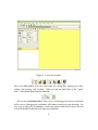
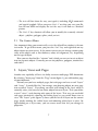
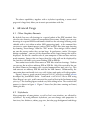
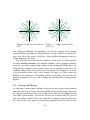
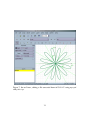
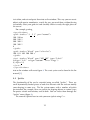
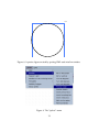
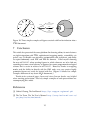
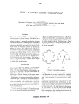
The PracTEX Journal, 2006, No. 2
Article revision 2006/05/12
Ipe — a graphics editor with LATEX integration
Jan Hlavacek
Email [email protected]
Website http://www.svsu.edu/∼jhlavace/
Address Saginaw Valley State University
7400 Bay Road
University Center, MI 48710
USA
Abstract The article talks about author’s experiences with the Ipe graphics editor.
The main features of Ipe are described, as well as some advanced usage. In
the section 6, a similar editor, vrr, is mentioned.
1
Introduction
Ipe is a graphics editor which runs on Windows, Linux, and Mac OS X and is wellsuited to preparing graphics for LATEX documents. In this article I will describe
Ipe’s features and usage, with several examples.
I first started using Ipe sometime in the mid-1990’s, when both my wife and
I were working on our dissertations at Ohio State University. My dissertation
1 2 3 4 5 6 7 8 9
1
A
1 1 1 1
B 1 1 1
1 1 1
C
D
Figure 1: An Ipe graphic made for a recent presentation
was in complex analysis and only included three pictures; however my wife’s
dissertation was in graph theory, and included about 200 illustrations. We looked
for a program that would make it easy to create these pictures and to include
them in a LATEX document. In time we stumbled upon Ipe and quickly found out
that it completely satisfied our needs.
The name Ipe is an acronym for Integrated Picture Environment, referring to
the clever file format the editor used. To solve the problem of integrating pictures
with LATEX text and formulas, Ipe saved all figures in a file that was at the same
time a valid LATEX file and a valid Postscript file. The LATEX part contained a
picture environment with all the text and math positioned in proper places. It
also contained code for including the file again, this time as a Postscript illustration with the rest of the drawing. You included the file as a regular LATEX file, and
it took care of everything else. Using Ipe including and handling pictures turned
out to be very easy.
Another feature of Ipe we appreciated perhaps even more than the ingenious
file format was Ipe’s snapping modes. In addition to your regular mouse cursor,
Ipe provided another cursor1 which snapped to various objects in the drawing.
In addition to the usual snapping to a grid, you could make it snap to lines and
curves, vertices of polygons, intersections of curves, and on top of that there were
two different angular snapping modes. All this made Ipe very powerful editor
for creating mathematical and scientific illustrations.
Several years later I tried to use Ipe on my computer at home which ran the
Linux operating system. I was able to compile Ipe but it simply refused to run.
It seemed to have some issue with the new version of the X Server, and it kept
crashing right after starting. I was unable to find any information about this
problem anywhere on the Internet, and for some reason (I don’t remember why)
I was not able to locate or reach the author of the program. I gave up, converted
all my old Ipe drawings to Postscript, and started learning METAPOST.
Come the fall of 2004, I decided to upgrade my Debian Linux system from
the rather aged “stable” distribution to the “testing” distribution. When paging
through a long list of new packages, my eye caught the name “ipe”. Version
6.0pre22, it said. At first I was skeptical: a different program with the same name,
I was thinking — happens all the time. Then I looked at the description:
1. This cursor is called fifi, after a dog from a popular computer game that runs around your
feet in a way similar to the behaviour of this secondary cursor.
2
Drawing editor for creating figures in PDF or PS formats. Ipe supports
making small figures for inclusion into LaTeX documents as well as
making multi-page PDF presentations . . .
There was more and it all sounded sort of like the old Ipe, except the part about
multi-page presentations. There was also a URL: ipe.compgeom.org.
I installed the package and visited the web page. It turned out that the author,
Otfried Cheong, had completely rewritten Ipe, getting rid of old legacy code and
using the newly available Qt toolkit. This meant not only that Ipe was easier
to use than before, but also that, thanks to the cross platform Qt toolkit, it was
now available for Unix and its clones, including Mac OS X, and Windows. There
was another important change: the old ingenious file format that Ipe was named
after was gone, replaced by a new XML-based format. However, in addition to
XML, Ipe can also save files in PDF and encapsulated Postscript formats.2 Ipe,
like many modern tools, understands Unicode. There were some other changes,
namely a new multiple-page presentation mode, which I will describe later.
2
Main Features of Ipe
Figure 2 shows the initial Ipe window. This screenshot was taken on a Windows
system, but the Linux version looks very similar. Most of the window is occupied
by a yellow drawing canvas (you can change the color of the canvas to white if
you prefer that) with a visible grid. On top of the window is the usual menu bar
and several toolbars.
2. In fact, Ipe can be configured so that every time you save a file in either the PDF or encapsulated Postscript format, the other format will also be saved automatically, which makes it
easy for a TEX document and its figures to be processed by both TEX and pdfTEX [see the Ask
Nelly column in this issue for a discussion of various kinds of image files TEX and pdfTEX can
process. — Ed.].
3
Figure 2: A new Ipe window
First is the file toolbar, with the usual icons for saving files, opening new files,
cutting and pasting, and so forth. What you do not find there is the “print”
icon — you cannot print directly from Ipe.
Next is the resolution toolbar. You can see and change the current resolution
of the canvas (changing the resolution will zoom in or out of your drawing). An
easy way to adjust the resolution is with your mouse scroll wheel; there are also
several keyboard shortcuts to change the resolution.
4
Probably the most useful toolbar contains snapping tools. Here you can change
your snapping mode, change grid size, and change the angle for angular snapping. The available snapping tools are:
– Vertex snapping (shortcut ‘F4’) — your cursor will snap to the vertices of
polygons and polylines, marks, and centers of circles.
– Boundary snapping (shortcut ‘F5’) — snaps to all lines and curves in your
drawing.
– Intersection snapping (‘F6’) — snaps to intersections of straight lines (currently, Ipe does not snap to intersections involving circles, arcs or splines).
– Grid snapping (‘F7’) — on and off (independently of snapping, you can toggle grid visibility with ‘F12’).
– Absolute angular snapping (‘F8’) — this is somewhat harder to explain. According to the manual [1], When angular snapping is enabled, the mouse position
is restricted to lie on a set of lines through the origin of your current axis system.
The lines are the lines whose angle with the base direction is an integer multiple of
the snap angle. The snap angle can be set in the second box in the Snap toolbar.
The origin of the axis system can be set using the ‘F1’ key, and the direction
using ‘F2’ key. You can also set the axis system to be parallel to an existing
line in you drawing by pointing at the line and pressing ‘F3’. The origin of
the axis system is also used as a center of scaling and rotation.
– Automatic (relative) angular snapping (‘F9’) — this one is used only when
creating a polygon or a polyline. It works in the same way as absolute
angular snapping, except that instead of using the origin of the axis system,
it uses the last created vertex of your polygon. That way you can easily
create a polygon or polyline in which all angles are multiples of the snap
angle.
You can use any number of snapping tools together.
5
The last visible toolbar is the objects toolbar. Use this to select your drawing tool.
Available tools are select, move, rotate, scale. pan, text, formula, paragraph, marks,
rectangles, polylines, polygons, three different ways of drawing arcs, three different ways
of drawing circles, splines, and splinegons. What most of these tools are for should
be fairly obvious to anybody who had previously used any drawing program.
However, here are some notes on the use of these tools in this particular drawing
program:
– When you select the pan tool, you can drag your canvas around to change
which part of your drawing you can see. I personally prefer to use the ‘x’
keyboard shortcut which centers the canvas window around the point your
cursor is currently over. My approach is to use the scroll wheel to zoom out
until I see the whole drawing, point at the part I want to work on, press ‘x’
which will center that part, and zoom in using the scroll wheel again.
– There are three text insertion modes.
The first mode is the simple Text label mode. You can use LATEX commands
in your labels, including math mode, color changes, different TEX fonts, etc.
You can load packages and set up definitions in the LATEX preamble, which
you can edit by going to the “Edit” menu and choosing “Document properties”. When selecting a font, be aware that Ipe can only use Type 1 or
TrueType fonts; Ipe cannot handle bitmapped Type 3 fonts. You can include
accented characters or characters from non-latin scripts transparently using
UniCode. The graphical user environment of Ipe handles UniCode transparently. Look in the Ipe manual ([1]) for instructions how to set up your
document preamble for inclusion of UniCode characters into LATEX.
The second text insertion mode is called Mathematical symbols. This is essentially the same as simple-text-label, except that it is processed by LATEX in
the math mode. It is actually equivalent to a text label in which everything
is enclosed by a pair of dollar signs.
The third text insertion mode is called Paragraphs. This will insert a LATEX
minipage environment into your picture. You can therefore use various
LATEX paragraph environments, such as ’center’, ’itemize’, etc. The ‘F10’ key
will insert a minipage that spans the entire width of your page.
6
– The text will first show the way you typed it, including LATEX commands
and special symbols. When you press ‘Ctrl-L’ or when you save your file,
Ipe will run LATEX and display the text the way it will look as a finished
picture.
– The ‘Ctrl-E’ key shortcut will allow you to modify the currently selected
object – polyline, polygon, spline, circle, or text.
2.1
The Context Menu
One important thing you cannot really see in the default Ipe window is the context menu. To get to this menu, you press the ‘Ctrl’ key and right-click on any
object drawn on your canvas. In the context menu you can change various properties of the object such as line thickness, color, text alignment, etc., depending
on the type of object.
Here you can also find the “scissors” tool, which you can use to cut an object
into two separate objects. Currently you can cut polylines, polygons, circular arcs
and circles.
3
Layers, Views and Pages
Another nice capability of Ipe is its ability to create multi-page PDF documents.
By selecting “Insert page” from the “Page” menu (figure 3), you add another page
to your document.
Not only can you have multiple pages, but each page can have several “layers”
and “views”. It works like this: You arrange your drawing objects on your page
into so-called “layers”. Everything you draw will belong to the layer which is
currently active, and you also can move objects between layers. Then you define
several “views”, each showing only some of the layers. That way you can build
each page interactively, showing and hiding layers as you switch from view to
view. The “layers” pane (figure 4) shows you the list of all layers on the current
page, clearly marking the visible layers and indicating which layer is active. By
right-clicking on a layer name, you can access menu that lets you change its
properties.
7
Figure 3: The “Page” menu.
Figure 4: The “Layers” pane with 5 layers, three of them visible in the current
view, the “gamma” layer active.
8
The above capabilities, together with a stylesheet specifying a screen sized
page and a large font, allow you to create presentations with Ipe.
4
4.1
Advanced Usage
Other Graphics Formats
By default, Ipe saves all drawings in a special subset of the PDF standard. You
can also save them in a subset of encapsulated Postscript. Finally, you can save
drawings in a special XML-based format which has the advantage of being easily
editable with a text editor or other XML processing tools. at the moment You
can insert a raster format images (such as JPEG or PNG files) into your drawing
by choosing “Insert Image” from the “File” menu. These images will be shown
on your Ipe canvas unless they are too large. In preferences, under “On-screen
bitmap resolution”, you can set the dimensions of the largest image that will be
displayed. Set this to a smaller value if your computer is slow or does not have
much memory. Images that are larger than this value will not be displayed by
Ipe, but they will show up in your resulting PDF or EPS file.
You cannot insert other Postscript or PDF files into Ipe drawings. Neither
can you use Ipe to edit an arbitrary EPS or PDF file. Only files created by Ipe can
be edited. However, Ipe comes with a special command line tool, pdftoipe. This
tool converts an arbitrary PDF file into the Ipe XML format. Unfortunately, the
conversion does not handle text very well; it does work quite well with graphics.
Figure 5 shows a graph created using METAPOST with the excellent macros
developed by Jean-Michel Sarlat. I converted a METAPOST file to PDF using
Hans Hagen’s mptopdf, and I converted the result of that to the Ipe format using
pdftoipe. The resulting figure needed very little editing in Ipe. The result of that
process is shown in figure 6. Figure 7 shows Ipe (this time running on Linux)
editing the file.
4.2
Stylesheets
Many properties of your picture, as well as Ipe’s user interface, are affected by
stylesheets. By using different stylesheets, you can change such properties as
font sizes, line thickness, colors, page size, but also page background and things
9
+1
+1
+1
+1
+1
+1
+1
Figure 5: Graph created in METAPOST
Figure 6:
pdftoipe
+1
Graph processed by
like a LATEX preamble for your document. You can, for example, have a special
stylesheet for presentations in which all fonts are larger, all lines are thicker, the
page is the size of the screen, which has a fancy gradient background, and uses
Lucida Bright or Arev fonts.
The stylesheets also affect the user interface. In Ipe you can switch between
so–called absolute attributes and symbolic attributes. When absolute attributes
are active, you choose colors using a color selection dialog with RGB values, and
things like line thickness, size of arrows, fonts etc. are specified in point units. In
symbolic mode, which is the default, you select colors, line thicknesses etc. from
a list of available names, such as red, normal, fat, large, etc. These names are
defined in the stylesheets. By loading different stylesheets, you can add new
options for colors or sizes, as well as change the meaning of the already present
options.
4.3
Cutting and Pasting
As with other vector graphics editors, in Ipe you can cut or copy selected objects
from your drawing and paste them into another file or another page of the same
file. But you can do more than that: Ipe objects are stored in the clipboard using
their XML representation. That means you can cut an object from Ipe, paste it
into a text editor window, edit it, cut it from the text editor, and paste it back into
Ipe. You can also write some of your drawing elements directly in XML in your
10
Figure 7: Ipe on Linux, editing a file converted from METAPOST using mptopdf
and pdftoipe.
11
text editor, and cut-and-paste them into an Ipe window. This way you can create
objects with precise coordinates, exactly the way you need them, without having
to carefully select your grid size and carefully click at exactly the right place on
the canvas.
For example, pasting
<i p e s e l e c t i o n>
<path s t r o k e =” . 3 . 5 1 ” pen=” normal ”>
100 100 m
300 100 l
300 300 l
100 300 l
h
</path>
<path s t r o k e =” b l a c k ” pen=” u l t r a f a t ”>
100 0 0 100 200 200 e
</path>
<t e x t s t r o k e =” b l a c k ” pos=” 305 305 ” type=” l a b e l ”
h a l i g n =” l e f t ” v a l i g n =” bottom ” s i z e =” Large ”>
$\ a l p h a 1 $
</ t e x t>
</ i p e s e l e c t i o n>
into an Ipe window will create figure 8. The exact syntax can be found in the Ipe
manual [1].
4.4
Ipelets
The functionality of Ipe can be extended using so called “ipelets”. These are
small dynamically loaded pieces of code that interact with Ipe and can modify
your drawing in some way. The Ipe system comes with a number of ipelets
pre-installed; for example, there are ipelets for aligning objects in various ways,
for precise stretch and rotation, and so forth. You can access them through the
“ipelets” menu (figure 9).
The manual explains how to write your own ipelets using C++.
12
α1
Figure 8: A precise figure created by pasting XML code into Ipe window.
Figure 9: The “ipelets” menu
13
5
Word of Caution
The current version of Ipe described in this article is Ipe 6.0 preview 26. It is a
great piece of software, and it makes my life much easier every time I need to
create illustrations to include in LATEX documents. Other people I know even use
Ipe to create drawings to include in Microsoft Word and other documents. It is
easy to use and powerful. However, as of this writing, it hasn’t been officially
released. It does have some bugs, and it has been known to break occasionally
under high-stress testing. Usual procedures, such as saving your work frequently,
should be followed when working on complex projects.
6
The VRR Editor
While working on this article, I ran across another editor that seems to have a lot
in common with Ipe in design and basic philosophy. It is the VRR editor, available
from http://atrey.karlin.mff.cuni.cz/projekty/vrr/ [2]. It has snapping capabilities similar to Ipe’s capabilities, it uses TEX similarly to Ipe, it can export
drawings in PDF or EPS, and so forth. It has several features not present in Ipe,
namely, it can snap to intersections of splines and circles, and it can also create geometric dependencies in a way similar to some popular dynamic geometry
software, such as Geometer’s Sketchpad, KIG, and others. In Ipe, if you snap
an object to, for example, an intersection of two lines and then you move one
of the lines so that the intersection changes, the snapped object is not going to
move and consequently will no longer be snapped to the intersection. This is how
most vector graphics editors with this kind of snapping work. In VRR, you can
specify a geometric dependency so that, for example, if you snap an object to an
intersection and the intersecting objects move and the intersection changes, the
snapped object also moves and stays snapped to the intersection. The VRR editor
can also import and export some additional file formats, for example svg. For
more information on VRR, please refer to the manual [2].
One major shortcoming of the vrr editor compared to Ipe is that it is not
cross-platform — it seems to run only on Linux. One thing I really like about Ipe
is that it works exactly the same way on my Linux system at home as it does on
Windows on my office laptop.
14
S1
11 12 1
2
10
α
9
3
β
8
7
6
4
5
E
1/3
S2
D
1/4
A
S4
1/4 B
1/2
D
F
1/3
C
1/4
S3
r
Figure 10: Three simple examples of figures created with Ipe for inclusion into a
LATEX document.
7
Conclusion
This article has presented the cross-platform Ipe drawing editor; its main features
are tight integration with LATEX, sophisticated snapping modes, extensibility via
ipelets, easy yet flexible user interface, customizable with stylesheets, and ability
to export commonly used PDF and EPS file formats. I find myself choosing
Ipe over METAPOST when creating figures in which elements are to be laid out
according to a more visual scheme, as opposed to a more programmatic or logical
scheme that is easier to achieve in METAPOST. However, thanks to snapping
modes and the ability to directly edit the XML code, even very precise highly
geometric figures can easily be created with Ipe. (Figure 10 shows few simple
examples from one of my recent LATEX documents.)
Thanks to its system of pages, layers and views, Ipe can also be very helpful
when creating presentation. Two very simple examples of such presentations are
accompanying this article.
References
[1] Otfried Cheong The Ipe Manual http://ipe.compgeom.org/manual.pdf
[2] The Vrr Team The Vrr User’s Manual http://atrey.karlin.mff.cuni.cz/
projekty/vrr/doc/man/manual/
15