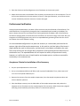
1
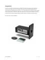
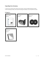
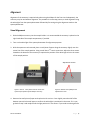
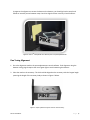
Installation and User Guide
60SpecTM 60 Degree Specular Reflectance
Accessory for UV-Vis Spectrophotometers
The information in this publication is provided for reference only. All
information contained in this publication is believed to be correct and
complete. PIKE Technologies, Inc. shall not be liable for errors contained herein
nor for incidental or consequential damages in connection with the furnishing,
performance, or use of this material. All product specifications, as well as the
information contained in this publication, are subject to change without notice.
This publication may contain or reference information and products protected
by copyrights or patents and does not convey any license under the patent
rights of PIKE Technologies, Inc. nor the rights of others. PIKE Technologies, Inc.
does not assume any liability arising out of any infringements of patents or
other rights of third parties.
This document contains confidential or proprietary information of PIKE
Technologies, Inc. Neither this document nor the information herein is to be
reproduced, distributed, used or disclosed, either in whole or in part, except as
specifically authorized by PIKE Technologies, Inc.
PIKE Technologies, Inc. makes no warranty of any kind with regard to this
material including, but not limited to, the implied warranties of merchantability
and fitness for a particular purpose.
Copyright 1991-2013 by PIKE Technologies, Inc., Madison, WI 53719. Printed in
the United States of America. All world rights reserved. No part of this
publication may be stored in a retrieval system, transmitted, or reproduced in
any way, including but not limited to, photocopy, photograph, magnetic or
other record, without the prior written permission of PIKE Technologies, Inc.
Address Comments to:
PIKE Technologies, Inc.
6125 Cottonwood Drive
Madison, WI 53719
Phone
Fax
E-mail
Web Site
January 2013
(608) 274-2721
(608) 274-0103
[email protected]
www.piketech.com
Contents
Introduction
1
Unpacking Your Accessory
2
Packing List
2
Accessory Description
Alignment
3
4
Visual Alignment
Fine Tuning Alignment
Performance Verification
4
5
6
Acceptance Criteria
Using Your Accessory
6
7
Reflectance Spectra and Applications
Precautions
9
10
Mirrors
Replacement Parts and Options
10
10
Introduction
For use in UV-Visible spectrophotometers, the PIKE Technologies fixed-angle specular reflectance
accessories are simple, easy-to-use accessories that mount into the standard sample slide of all
spectrophotometers equipped with an optional 2” x 3” sample slide holder. The design enables samples
to be analyzed quickly in reflectance mode. Some analyses that may be performed with this accessory
include the measurement of sample reflectance and the analysis of coatings on metallic surfaces.
This user manual covers the 60Spec.
PN 350-1216000-02
P a g e |1
Unpacking Your Accessory
In order for you to quickly verify receipt of your accessory, we have included a packing list. Please
inspect the package carefully. Contact PIKE Technologies immediately if any discrepancies are found.
Packing List
60Spec Manual
60Spec Accessory
Masks
PN 350-1216001
PN 121-6000
PN 121-0502
Quantity 1
Quantity 1
Quantity 2
Alignment Mirror
PN 300-0039
Quantity 1
PN 350-1216000-02
P a g e |2
Accessory Description
The beam from the spectrophotometer is reflected from the first mirror to strike the sample. The angle
of incidence of the beam at the sample is engineered to be the angle specified for the particular
accessory. The reflected beam from the sample is then reflected at the second mirror and passes to the
instrument detector.
The accessory includes a set of two apertures to support small samples and a reference mirror for
alignment of the accessory by means of the adjustment screws.
Sample Position
Figure 1. Optical diagram of the 60Spec accessory
PN 350-1216000-02
P a g e |3
Alignment
Alignment of the accessory is required only when using the 60Spec for the first time. Subsequently, the
accessory may be used without alignment. The procedure is a two-step process, a visual alignment using
the white light from the spectrophotometer followed by fine tuning using the alignment mode on the
spectrophotometer.
Visual Alignment
1. Slide the 60Spec accessory into the sample holder. It is recommended the accessory is placed on the
right hand side of the sample compartment, if possible.
2. Turn on the white light of the spectrophotometer for alignment purposes.
3. With the aperture mask removed, place a small piece of paper along the accessory slightly over the
center line of the sample position. Using a small Post-ItTM note is convenient. Adjust the three screws
located on the bottom of the accessory to optimize the position of the white light to be in the center
of the sample position.
Adjustment Screws
Figure 2. Post-ItTM note placed over the center line
of the sample position of the 60Spec accessory.
Figure 3. Bottom view of 60Spec and
adjustment screws.
4. Remove the small piece of paper and replace it with a mirror. Cover slightly more than half of the
detector port with the small paper to confirm the white light is positioned in the center. If it is not,
go back to step 3 and readjust until the light position is in the center. If you need to make significant
PN 350-1216000-02
P a g e |4
changes to the alignment to center the beam on the detector, you should go back to step 3 and
follow an iterative process between steps 3 and 4 to align the beam correctly in both locations.
Figure 4. Post-ItTM note placed over detector port in a spectrophotometer.
Fine Tuning Alignment
1. Go to the alignment mode in the spectrophotometer control software. Final alignment using the
detector energy signal requires the use of green light to avoid saturating the detector.
2. Place the mask on the accessory. The slit should be aligned on the accessory with the longest length
spanning the length of the accessory body as shown in Figure 5 below.
Figure 5. Proper placement of the mask on the accessory.
PN 350-1216000-02
P a g e |5
3. Place the aluminum-surfaced alignment mirror face down on the accessory mask.
4. Adjust the three screws in the bottom of the accessory to maximize the UV-Vis transmission. Turn all
three screws clockwise by the same amount (1/4 turn). If the signal decreases, turn all three screws
counter clockwise by twice the amount to increase the signal.
Performance Verification
Among the spectrophotometers, the beam of the instrument may be collimated or focused beam. The
collimated beam is not significantly changed by the increased beam path caused by the 60Spec. The
beam is almost the exact size and shape of the mask supplied with the 60Spec. With a focused beam,
the beam is diverging when it reaches the mask. The effect is to lose some energy at the mask. Also, the
elongation of the diverging beam may result in an expanded beam geometer greater than the area of
the collector lens on the detector housing.
The recommended configuration is to place the accessory in a slide holder positioned at the
extreme right side of the sample compartment. In this position, the focal point of the beam is
slightly below the mask in the accessory, and the beam is only slightly occluded by the mask.
There may still be some loss of light due to expansion of the beam beyond the dimensions of
the detector lens. The expanded beam will not impact the validity of experimental results,
however, as it will be the same in both baseline and sample spectra, and thus accounted for
consistently in the measurement.
Acceptance Criteria for Installation of the Accessory
1. Set your spectrophotometer to scan mode.
2. Set up a scan between 400 nm and 700 nm with a spectral bandwidth of 2 nm, a data interval of
1 nm and a scan speed of 600 nm/min.
3. Remove the accessory from the sample compartment, close the sample compartment door and
collect a baseline spectrum.
4. Place the 60Spec accessory into the slide holder of the sample compartment and position the
alignment mirror face down over the sample position of the accessory. With the accessory aligned
according to the installation procedure, collect a % transmission spectrum.
PN 350-1216000-02
P a g e |6
5. The throughput value at 500 nm for the 60Spec specular reflectance accessories should be greater
than 15%. An example of a typical throughput spectrum using the 60Spec collected is shown in
Figure 6.
If your accessory does not meet this minimum value, we recommend realigning the accessory. If this
does not remedy the issue, contact PIKE Technologies. Please have the serial number of your accessory
available. This number is found on the rear of the accessory.
Figure 6. Energy throughput spectrum of the 60Spec.
Using Your Accessory
To collect a spectrum with your 60Spec accessory perform the following steps:
5. Collect a baseline 100%R spectrum by using the alignment or another suitable mirror placed over
the mask.
6. Place the sample face down on the 60Spec mask. The slit should be aligned on the accessory with
the longest length spanning the length of the accessory body as shown in Figure 5.
7. Scan the spectrum according to instructions provided with your UV-Vis spectrophotometer.
PN 350-1216000-02
P a g e |7
% Reflectance
Figure 7. Example spectrum of gold-surfaced mirror using 60Spec for UV-Vis spectrophotometers using the
alignment mirror as a background.
PN 350-1216000-02
P a g e |8
Reflectance Spectra and Applications
Specular reflectance spectroscopy is used to measure the reflectivity of substrates or optical
components and coatings on such substrates. The following spectrum is an example of a laser mirror
measured in the UV-Vis spectral region using the 60Spec specular reflectance accessory. Prior to data
collection a baseline was collected using the alignment mirror.
Figure 8. Laser mirror measured using the 60Spec (alignment mirror as a background).
A Note on Reflectance Data of >100%R
When measuring a dielectric mirror with 99% absolute reflectance, using a metal mirror with 91%
absolute reflectance as the 100% baseline will result in reflectivity values above 100%. In this example,
the measured reflectivity would be 109%.
PN 350-1216000-02
P a g e |9
Precautions
Mirrors
To provide the maximum transmission in the UV-Vis, with minimum spectral interferences, the mirrors
used in this device are uncoated (bare) aluminum on a glass substrate. Since the coatings are soft, care
must be taken to avoid damage. Normally, these mirrors will not need cleaning, since they are contained
within the housing of the accessory. If they do need cleaning, they may be gently wiped with a lint-free,
abrasive-free cloth, such as lens tissue, or with a camel hair brush.
Under no circumstances must the mirrors be rubbed with paper products such as KleenexTM or
KimwipesTM since this will scratch the mirror coating.
Replacement Parts and Options
Part Number
121-0502
300-0039
PN 350-1216000-02
Description
Mask Set
Alignment Mirror
P a g e | 10
6125 Cottonwood Drive · Madison, WI 53719-5120 · (608) 274-2721 (TEL) · (608) 274-0103 (FAX)
[email protected] · www.piketech.com