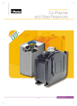
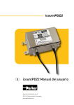
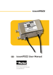
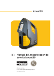
1
Condition Monitoring Products & Custom Solutions icountLaserCM20 Fluid Condition Monitoring Portable Particle Counter A 2-minute contamination test procedure: A portable particle counter designed to be used in the field icountLCM20 is a proven answer to fluid system contamination monitoring offering a 2-minute test procedure. Multi-standard ISO and NAS cleanliness reporting, data entry, data graphing and integral printing are all standard on this world proven contamination monitor. Product Features: • icountLCM20 is a proven answer to fluid system contamination monitoring. • 2-minute test procedure. • Multi-standard ISO, NAS and AS4059 cleanliness reporting. • Data entry, data graphing and integral printer. • 420 bar rated maximum pressure. • Supported by the offline UBS and online SPS accessories. icountLaserCM20 Portable Particle Counter Features & Benefits Test time: 2 minutes Particle counts: MTD 4+, 6+, 14+, 21+, 38+ and 70+ microns(c) ACFTD 2+, 5+, 15+, 25+, 50+ and 100+ microns International codes: ISO 7-22, NAS 0-12 Data retrieval: Memory access gives test search facility Max. working pressure: 420 bar Max. flow rate: 400 I/min when used with system 20 Sensors. Higher with single point sampler (see page 357) Working conditions: LaserCM will operate with the system working normally Computer compatibility: Interface via RS232 connection @ 9600 baud rate. Special ‘diagnostics’ are incorporated into the icountLaserCM microprocessor control to ensure effective testing. Routine contamination monitoring of oil systems with icountLaserCM saves time and saves money. Contamination monitoring is now possible during applicaton operation - icountLaserCM saves on production downtime. Typical Applications Construction machinery Industrial plant Hydraulic equipment & system manufacturers Research & testing institutes Offshore & power generation Marine Military equipment applications Parker LaserCM Portable Particle Counter. With 20 years experience in manufacturing the world’s best selling ‘white light’ portable particle counter – CM20, the progression to the icountLaserCM with its opto-mechanical, continuous wave single point source laser (SPSL) is both a natural and customer driven development. Data entry allows individual equipment test log details to be recorded. Data retrieval of test results from memory via hand set display. Automatic test cycle logging of up to 300 tests can be selected via hand set display. Totally portable, can be used as easily in the field as in the laboratory. Automatic calibration reminder. Instant, accurate results achieved with a 2 minute test cycle. Data entry allows individual equipment footprint record. Data graphing selectable via the integral printer. Auto 300-test cycle logging via LCD handset input. RS232 to USB computer interface. Limit level output to control peripheral equipment such as off-line filtration via internal relay limit switches. Auto-testing allows for the conducting of automatic sequencing tests on flushing systems for example. Optional bar code swipe wand to allow handset data loading. Worldwide service and technical support. Re-calibration - Annual certification by an approved Parker Service Centre. icountLaserCM20 Specifications Automatic Particle Counters (APC’s), have been widely used for many years in condition monitoring of hydraulic fluids. However, it is only recently that APC’s have become flexible enough to enable the instruments to be taken out of the laboratory and used on-line in order to obtain the most credible form of results. Unusually, the move from fixed laboratory use, to portable field use has not been at the expense of accuracy or user flexibility, but has actually enabled the instruments to be used over a wider range of applications and situations. The most common monitoring technique used in APC’s is that of light obscuration or light blockage. Here, a focused light source is projected through a moving column of oil, (in which the contaminants being measured are contained), causing an image of the contaminant to be projected on to a photo diode cell, (changing light intensity to an electrical output). The electrical output of the photo diode cell will vary in accordance with the size of the particles contained in the column of oil; the larger the particle, the bigger the change in the photo diode electrical output. On-line APC’s must be able to test the oil sample at whatever cleanliness it is delivered to the machine. Parker therefore had to develop technology to ensure the on-line APC was able to test a sample without the conventional laboratory technique which requires dilution - a practice that would have been simply impossible with a portable unit. By careful design and window sizing, gravimetric levels as high as 310mg of dirt per litre, (equivalent to up to 4 million particles >6 micron per 100 ml), can be achieved without making the instrument susceptible to counter saturation. These high saturation point on-line APC’s, whilst losing none of the accuracy of their laboratory counterparts, enable particle counting to be carried out quickly and accurately. A focused light source is projected through a moving column of oil. Laser Optical Sensing Core technology that proves itself in icountLaserCM The icountLaserCM portable particle counter features microprocessor controlled optical scanning for accurate contaminant measurement with a calibration range from ISO 7 to ISO 22 with no counter saturation. How does icountLaserCM work? – The particles are measured by a photo diode that converts light intensity to a voltage output which is recorded against time. – As the particle moves across the window the amount of light lost is proportional to the size of the particle. This reduction in voltage is measured and recorded. – This “voltage” lost relates directly to the area of the particle measured, is changed into a “positive” voltage and then in turn changed into a capacitance value. – This value is counted and stored in the icountLaserCM computer in one of 6 channels according to particle size. – Readouts are displayed on the hand-held LCD in the accepted ISO and NAS standards ready for hard copy printing or RS232 computer download. – The on-board computer allows storage of up to 300 test results. icountLaserCM20 Portable Particle Counter Description LaserCM LaserCM (LCM20 20 22) (LCM20 20 62) 32 Specification ABS handheld display Mechanical composition – Brass, 126 ABS structural foam and injection moulded case plated steel, stainless steel and aluminium Fluorocarbon seals Nylon hoses (kevlar braided microbore) 28 Perfluoroelastomer seals Stainless steel armoured hose ends 1.2m fluid connection hose 12Vdc power supply 249 Rechargeable battery pack Fast blow fuse Unique optical scanning system Bonded glass optical window enclosed in SS plate Micron channels analysis (Six) Analysis range ISO 7 to 22 incl. (NAS 0 to 12) 32 character dot matrix LCD. Alpha numeric keypad Data retrieval Calibration to ISO standards* Viscosity range 2 to 100 cSt. 500 cSt.with SPS Operating temp.+5 to +80°C Ambient temp.+5 to +40°C 2 minute test completion time Memory store – 300 test memory Battery operated 6 x 1.5 D cells Phosphate Ester group compatibility Mineral oil & petroleum based fluid compatibility Commissioning Kit Up to 420 bar (6000 psi) Integral 16 column printer Power supply Limit socket, fuse & jack plug Screwdriver ParSmart & cable assy RS232 to USB computer interface Astra board case weight – (Kg) Unit weight – (Kg) ParSmart software and cable link pack Weather protector cover CE certified Auto logging *Note: In compliance with international standards, all Parker portable particle counters can meet the ISO Medium test dust standards. The icountLaserCM’s, in addition to the complete range of Condition Monitoring products, are capable of achieving certification to ISO 4406:1999 and with traceability to ISO 11171 for SRM 2806, via ISO 11943. Re-chargeable battery pack Instruction manual & bar code software Power lead, printer ribbon, bar code pen & weather cover Batteries & printer reel icountLaserCM20 Operation icountLCM20 Using SPS Operating the Parker icountLaserCM is as simple as pressing the start button and turning the dial. The test procedure is automatic and in the case of the icountLaserCM takes no more than 2 minutes to complete. Understanding MTD icountLCM20 makes the difference in industry MTD (Medium Test Dust) having a particle size distribution close to ACFTD was selected as a replacement. However, MTD produced results somewhat different to ACFTD, so the NIST (National Institute of Standards & Technology) undertook a project to certify the particle size distribution of ISO MTD. Fully accredited to BS EN 60825:1992 and IEC 60825-1 (safety of laser products) Standards, accredited to USA Standards and achieving full ISO certification. icountLaserCM offers users advanced laser technology, a fast, dynamic and on-line 2 minute system test cycle. An icountLaserCM Aggressive Fluids model is also available, suitable for monitoring corrosive fluids such as phosphate ester based lubricants used in commercial aviation. ACFTD (Air Cleaner Fine Test Dust) was formatted in the 1960’s, but is no longer being produced. The obsolescence of this dust has led to the adoption of a new dust MTD. The result was particle sizes below 10μm were greater than previously measured. Particles sizes reported based on NIST would be represented as μm (c), with “c” referring to “certified”. Therefore the icountLCM20 reported sizes are as follows: MTD calibration icountLaserCM MTD Calibration variants are certified via a primary ISO 11171 calibrated automatic particle counter. All MTD Laser CM20’s achieve ISO 4406:1999 criteria, via ISO 11943. icountLCM20 Using SPS ACFTD MTD 2μ 4μ (c) 5μ 6μ (c) 15μ 14μ (c) 25μ 21μ (c) 50μ 38μ (c) 100μ 70μ (c) MTD offers true traceability, improved particle size accuracy and better batch to batch reproduction. icountLaserCM20 Portable Particle Counter Why On-Site Fluid Contamination Monitoring? Certification of fluid cleanliness levels. Early warning instrument to help prevent catastrophic failure in critical systems. Immediate results with laboratory accuracy. To comply with customer cleanliness requirements and specifications. New equipment warranty compliance. New oil cleanliness testing. Data Download Management Dedicated software, provides the link between an icountLaserCM20 and the H2Oil - Water in Oil monitor and your computer management system. 16-column printer for hard copy data. A feature of the icountLaserCM is the on-board printout data graphing option developed to support predictive maintenance procedures. icountLaserCM Test ON LINE TEST icountLaserCM Test ON LINE TEST TEST NUMBER 022 D M Y 04-03-10 15-52 20/15/09 Date Time ISO: Count / 100ml >4μ (c) >6μ (c) >14μ (c) >21μ (c) >38μ (c) >70μ (c) 820721 31564 314 64 14 0 NOTES TEST NUMBER 022 Date Time NAS CLASS: D M Y 04-03-10 15-52 7 Count / 100ml 4/6μ (c) 6/14μ (c) NAS CLASS 14/21μ (c) NAS CLASS 21/38μ (c) NAS CLASS 38/70μ (c) NAS CLASS >70μ (c) NAS CLASS 789157 31250 7 250 3 50 3 14 4 0 0 NOTES ISO 4406 - 1999 Correlation to NAS 1638 icountLaserCM20 Portable Particle Counter Introducing the new icountLCM ‘Classic’ There is a new addition to the proven range – the icountLCM ‘Classic’. Only available from Parker, the ‘Classic’ retains all the technology that made the icountLaserCM one of the most accurate, reliable and popular portable particle counters available. Classic icountLCM20 Our design engineers have re-configured the icountLaserCM specification in a way that has reduced our manufacturing costs. These savings have been passed onto icountLCM ‘Classic’ customers. Calibration certificate How have we done this? Parker listened to our existing customers and then to the engineers and maintenance operatives to find out the features that make the icountLaserCM a unique predictive maintenance instrument. Empty battery pack Then, we removed peripheral items such as the aluminium case and all the accessories, so a customer receives the icountLCM, with a CD user guide, professionally and securely boxed. One thing that has not altered is the icountLCM accuracy and icountLCM reliability. Our in-house software engineers have re-configured the EPROM, removing Data programming, User ID, Automatic Testing, Data retrieval, Alarm level settings, the barcode pen and Graph printing functions to reduce costs still further without in any way reducing the efficiency of the icountLCM. The icountLCM ‘Classic’ remains an instrument to be proud of. CD user guide Ordering Information (icountLaserCM and ‘Classic’ icountLaserCM) Part Number Supersedes Description LCM202022 LCM20.2022 icountLCM20 (MTD calibrated) LCM202026 LCM20.2026 icountLCM20 ‘classic’ (MTD calibrated) ACC6NE015 B84702 Printer roll x 5 ACC6NE014 P.843702 Printer ribbon ACC6NE013 B84609 Re-chargeable battery pack ACC6ND002 P849603 Weather protector cover ACC6ND000 B84703 USB to RS232 Download Cable Note 1: Part numbers featured with bold highlighted codes will ensure a ‘standard’ product selection. Note 2: Alternate displayed part number selection will require you to contact Parker Filtration for availability. Model LCM202022 Fluid Type Options 2 Hydraulic mineral 1 icountLCM20 (ACFTD calibrated) 6 Skydrol 2 icountLCM20 (MTD calibrated) 3 icountLCM20 (ACFTD calibrated) + bar code pen 4 icountLCM20 (MTD calibrated) + bar code pen 5 icountLCM20 ‘classic’ (ACFTD calibrated) 6 icount LCM20 ‘ classic’ (MTD calibrated) Note 1: Part numbers featured with bold highlighted codes will ensure a ‘standard’ product selection. Note 2: Alternate displayed part number selection will require you to contact Parker Filtration for availability. Carton box supplied to house kit Universal Bottle Sampler Simple and efficient offline oil sampling Clean and contamination free sampling Ideal for batch oil sampling and laboratory testing The UBS provides the dynamic link to portable particle and water counters. The UBS off-line sampler has microprocessor technology to recognise and adjust to the connecting monitor including the icountLCM20 and H Oil water in oil monitor. 2 Product Features: Simple operation Efficient testing procedure Clean and contamination free sampling Available for both mineral based and aggressive fluids Further advances the LCM20’s flexibility into laboratory bottle sampling environments Can accept various different sized bottles Minimal working parts Internal auto setting fuse for overload protection Simple maintenance procedures Universal Bottle Sampler Specifications Description Viscosity range 2 to 250 cSt Operating temp +5 to +80°C Test time 2m15s / 4m15s (Flush 2m) 12 Vdc power supply Extruded aluminium construction Unit weight - (Kg) Mineral oil and petroleum based compatibility Phosphate Ester group compatibility CE certified Military approved Manual operation Bottle pack De-gassing chamber Manual Sample tube pack Interface cable to LCM20, H2Oil etc. 151 319 Installation Details 147 165 11 120 CTRS 80 CTRS 100 CTRS 179 Universal Bottle Sampler Simple and Efficient Offline Oil Sampling System Flow Rate Samples are best taken from a point in the system where the flow is TURBULENT (Reynolds No. greater than 4000). The turbulent flow creates a mixing action. Where flow is streamline or LAMINAR, larger particulate may tend to settle toward the lower pipe surface and not be sampled. System Condition Changes Changes in the system operating condition, flow, temperature, pressure or vibration, can result in previously sedimented contaminant being retrained into the flowing oil. It is also possible that these changes may cause partially contaminated filter elements to shed particulate into the system. Samples should, therefore, be extracted when the system is in a steady state condition and the result less likely to be distorted by contaminant peaks. There are a number of proprietary sampling valves available which adhere to good theoretical principles. However, they do tend to generate a level of precision and cost which is unnecessary for trend monitoring. Sampling points should enable extraction of a sample without changing the system’s condition. Fine control needle valves are not desirable, as they have a tendency to silt up under some operating conditions, causing the distribution of contaminants in the fluid to be changed. The sampling port should be protected to maintain cleanliness and thoroughly flushed before collecting the sample for analysis. Allow sufficient airspace in the bottle to enable 80% fill. Bottle Cleanliness It is preferable that bottles have sealing screw caps and both parts are cleaned to a suitable level in accordance with ISO3722. The bottle should not contain more than one tenth the number of particles per 100ml than are expected to be monitored. Standard Parker bottles ae supplied clean to ISO13/11 (NAS Class 4) and should not be used to accurately count oils cleaner than ISO 15/12 (NAS Class 6) although they may be used for “trend mlonitoring” at lower levels. The bottle should remain capped until time of sample filling and re-capped immediately afterwards. Sample Mixing Sedimentation of contaminant in a sample will occur, the rate of which is dependent upon both fluid and particle characteristics. Samples should be analysed, without delay, once agitated and de-glassed. ACC6NW001 x 50 = ACC6NW002 ACC6NK001 Universal Bottle Sampler Ordering Information Standard products table Part Number Description UBS9002 Universal bottle sampler (includes aluminium case and accessories) UBS9003 Universal bottle sampler UBS9004 Aggressive universal bottle sampler UBS9005 Aggressive universal bottle sampler (Includes aluminium case and accessories) Accessories Part Number Supersedes Description ACC6NK001 B89907 Sample bottle pair no cap ACC6NW001 B89911 Sample bottle pair with extraction hose ACC6NW002 B89910 Sample bottle pack (50 x ACC6NW001) ACC6NK002 S840054 UBS power supply ACC6NK003 S890005 UBS degassing chamber and pump ACC6NK004 B89603 UBS degassing chamber only ACC6NK005 B89902 Cable and adaptor Note 1: Part numbers featured with bold highlighted codes will ensure a ‘standard’ product selection. Note 2: Alternate displayed part number selection will require you to contact Parker Filtration for availability. Typical Applications Batch sampling Aircraft rig certification Oil research Laboratory testing Transfer line monitoring Simple To Use UBS The oil sample is drawn into the UBS Off-line where it is secured, free from further contamination, in a bottle together with a clean waste bottle by a peristaltic, selfpriming pump. Simple operation and efficient testing are assured once the UBS Off-line is connected to any of the CM monitors, and powered up using it’s own power source. The oil sample requires agitation and de-gassing before carrying out the contamination test. A de-gassing kit option is available and consists of a vacuum chamber and pump. (Standard with UBS9002) icountBS - Bottle Sampler The benchtop solution to fluid contamination bottle sampling The Complete Solution - Industrial Design Combined with State of the Art Technology The icountBS - Bottle Sampler from Parker, with its innovative industrial design, has been developed for customers looking for state of the art technology, attention to detail and the compactness of a permanent laboratory particle analysis instrument. Combine this with on-board, laser based, leading edge technology to bring to all industries a truly revolutionary Particle Counter. The innovative icountBS is a product from the next generation of Parker’s fluid particle analysis and monitoring solutions. The IBS features an easy to use interactive touch screen, environmentally controlled pressurized bottle chamber, an internal compressor pump, automated door locking mechanism, sample tube cleaning sleeve that minimizes cross contamination, and an internal printer. The icountBS benefits from Parkers knowledge and experience of providing fluid analysis equipment to the market for over 15 years. icountBS - Bottle Sampler Features & Benefits • Customer programmable number of sample runs/sample bottle averaging and pre-test flush volumes from 10ml min. to 100ml max. • Input via fluid resistant touch screen display. • Repeatable and reproducible performance to ISO4406:1999 and NAS1638 particle count distributions. For other calibration standards consult Parker Hydraulic Filter Division. • On-board compressor and ‘shop’ air capable. • Design concept allowing for portability. DC and rechargeable battery pack options built in. • Sample tube self cleaning sleeve minimizing cross contamination. • 500 test sample memory. • Data download via USB jump drive included. • Internal printer. Home Screen Sample ID Input Number of Sample Runs Sample Volume Flush Volume Start Test Analyzing the Test Results Once the automatic oil sample test has been completed, what next? Solid contaminants in fluid power systems vary in size, shape, form and quantity. The most harmful contaminants are normally between 6 microns and 14 microns. The ISO code is the preferred method of reporting quantity of contaminants. The ISO code number corresponds to contamination levels relating to three sizes. The first scale number represents the number of particles that are equal to and greater than 4μm (c) per 100 milliliters of fluid, the second number for particles that are equal to and greater than 6 μm(c) per 100 milliliters of fluid and the third number for particles that are equal to and greater than 14 μm(c) per 100 milliliters of fluid. greater than 4μm(c), between 130,000 and 250,000 particles that are equal to and greater than 6μm(c), and between 8,000 and 16,000 particles that are equal to and greater than 14μm(c). For example: An ISO code 20/18/14 indicates that there are between 500,000 and 1,000,000 particles that are equal to and Component Cleanliness Guide Suggested acceptable contamination levels for various hydraulic systems Target Contamination Class to ISO 4406: 1999 4 μm(c) 6 μm(c) Suggested Maximum Particle Level 14 μm(c) 4 μm(c) 6 μm(c) Sensitivity Type of System Typical Components Silt-sensitive control systems with very high reliability. Laboratory or aerospace High performance servo valves 14 μm(c) 15 13 9 16,000 4,000 250 Super critical 17 15 11 64,000 16,000 1,000 Critical High performance servo and high pressure long life systems, e.g. aircraft, machine tools, etc. Industrial servo valves 18 16 13 130,000 32,000 4,000 Very Important High quality reliable systems. General machine requirements Piston pumps, proportional valves, compensated flow controls 20 18 14 500,000 130,000 8,000 Important General machinery and mobile systems. Medium pressure, medium capacity Vane pumps, spool valves 21 19 15 1,000,000 250,000 16,000 Average Low pressure heavy industrial systems, or applications where long life is not critical Gear pumps, manual and poppet valves, cylinders 23 21 17 4,000,000 1,000,000 64,000 Main protection Low pressure systems with large clearances Ram pumps Notes: Tables have been generated by organizations in various industries. Some of the tables are defined in cumulative counts, e.g. ‘>6μm’ and others are represented as differential counts e.g. ‘6-14μm’. All μm(c) refer to MTD distributions. All μm references will refer to ACFTD distributions. All standards are in counts per 100ml and provide easy methods for converting particle counts into limits that are simple to interpret. By noting the requirements of the standard, particle counts can be accurately converted to contamination levels. icountBS Product Specification Principle of Operation Laser based light obscur Calibration Dust MTD or ACFTD Dimensions H=20.9” x W=7.48” (8.27” Door) x D=16.1” Weight 39.7 lb. (18kg) Mechanical Composition Stainless steel 316, plated mild steel and aluminum Plastics Composition Precision polyurethane RIM moldings and ABS plastic Environmental Operating Temperature (Tested) 41°F to 140°F (+5°C to +60°C) Operating RH Range 20 - 85% [Tested at 86°F (30°C), no condensation] Storage Temperature 40°F to 194°F (-40°C to +90°C) Storage RH Range 10 - 90% (Tested at 30°C, no condensation) Channel Sizes MTD - >4μ(c), >6μ(c), >14μ(c), >21μ(c), >38μ(c), >70μ(c), ACFTD - >2μ(c), >5μ(c), >15μ(c), >25μ(c), >50μ(c), >100μ(c) Analysis Range ISO 7 to 21, NAS 0 to 12 Contamination Standards MTD - ISO 4406:1999 & NAS 1638 ACFTD - ISO 4406:1987, ISO 4406:1991 & NAS 1638 For further contamination standards consult Parker CMC Calibration Standard ISO MTD and ACFTD calibration to traceable ISO Standards. (Contact Parker CMC for further details) Fluid Management Maximum single sample = 100ml, Minimum single sample = 10ml Possible Test Configurations User selectable from single test up to 5 tests per run (eg. 1 x 100ml up to 5 x 50ml per run) Pre-Test Flush Volume Minimum = 10ml, Maximum = 100ml Viscosity Range 5 to 400 cSt Fluid Compatibility Mineral oils, petroleum and hydrocarbon based fluids (consult manufacturer) and some esters (consult manufacturer) Sample Bottle Size No specific bottle required. Maximum size = 2.95” (Dia.) x 5.90” (H). Maximum volume = 250ml Memory Storage 500 tests (capacity warning after 450 tests) Output Display Backlight 256 color STN transmissive Output Display Resolution 320 x 3 (RGB) (H) x 240 (W) dots Display Active Area 115 (H) x 86 (W) mm Data Input Via icon driven resistive touch screen Printer Thermal dot-line printing Printer Paper Ø50mm - (57mm x 25mm) Test Certification Calibration & Certificate of Conformity Power Supply DC output - 12V @ 6.60Amps, 80 watts max. AC input - 100 to 240V @ 1.2Amps (50 - 60 Hz) Battery Power 2 hours (recommended to be fully charged every 3 months) Battery Stand-By Time 1 month (then 1 hour of operation) Battery Fuse 6.3 Amps (anti-surge) Air Pressure Source 50 psi (3.5 bar) internal mini-compressor or 101 psi (7 bar) shop air icountBS - Bottle Sampler Ordering Information Key IBS Fluid Type 1 Mineral Calibration 1 ACFTD 2 MTD Future Option Future Future Future Transportation Power Supply Option Option Option Case Region 0 Lab Unit Accessories 0 0 Part Number 250ml Sample Bottle (2/pk) ACC6NW001 Sample Bottle Pack (50) ACC6NW002 Vapour/Waste Bottle ACC6NW003 Waste Bottle Folder ACC6NW004 Printer Paper Reel (x1) ACC6NW005 UK Power Supply ACC6NW006 USA Power Supply ACC6NW007 European Power ACC6NW008 1 Included * (2 pks.) * * * Transport Case P893865 * 1m Waste Tube (Clear) ACC6NW009 * 1m Vapour Hose (Blue) ACC6NW010 * USB Memory Stick ACC6NW011 * icountBS CD Manual ACC6NW012 * * These items included with IBS unit within a transportation case. 0 No Case 0 UK 1 Case 1 USA 2 Europe Single Point Sampler Online Sampling Lightweight and compact connection mineral based fluids The effective link to ensure accurate contamination monitoring The SPS (Single Point Sampler) is a lightweight, compact and easy to use online sampling unit that connects an icountLCM20 or H Oil to a single pressure test point in a fluid system. Suitable for use with mineral and biodegradable oils, petroleum based and phosphate ester fluids, the SPS offers fingertip operated control even at high pressures - 420 bar (6000 PSI) rated maximum pressure. 2 aggressive/phosphate Ester fluids Product Features: • Lightweight, compact and easy to use online sampling unit. • Connects an icountLCM20 or H Oil to a single pressure test point in a fluid system. • Suitable for use with mineral and biodegradable oils, petroleum based and phosphate ester fluids. • 420 bar (6000 PSI) rated maximum pressure 2 Single Point Sampler Online Sampling Features & Benefits The Single Point Sampler provides a means to connect an icountLCM20 or H2Oil to a single pressure test point and balance the differential pressure across the system, to provide a controlled flow of oil into the icountLCM20 or H Oil and away into a waste oil receptacle. 2 Lightweight, compact and easy to use design Fingertip operated control valve even at high pressures 420 bar (6,000PSI) rated Facilitates testing from large diameter pipework Capability to test up to 500cSt viscosity oils (pressure permitting) Pressure compensated flow control mechanism Possible to control the valve with the same level of accuracy whether the device is operating at high or low pressure Capable of allowing a flow rate in excess of 10ml/min when operating at any viscosity within the product specification Suitable for fluid temperatures from +5°C to +80°C (+41°F to +176°F) High quality polished finish. (stainless steel/ aircraft grade aluminium) Capable of working with an icountLCM20 or H2Oil connected into a system via the standard one metre extension hose kit Suitable for use with mineral and biodegradable oils, petroleum based and phosphate ester fluids Phosphate ester version utilises the 5/8” BSF HSP style fitting Designed so that it meets the lowest possible level of magnetic permeability Supplied with accessories kit It will maintain the set flow rate between upper and lower limits within a 100 bar inline pressure change Clear product identification to ensure that it is connected correctly. (i.e. downstream of the icountLCM20 or H2Oil) Connection Instructions System (F) (D) Prs. R (A) 7. Single point sampler (C) (E) P1 P2 icountLCM20 or H2Oil (B) 1. 2. 3. 4. 5. 6. Ensure valve is closed (A). Connect P2 on icountLCM20 or H Oil (B) to P2 on Single Point Sampler (SPS) (C). Connect drain line on SPS (D). Connect P1 of icountLCM20 or H Oil (E) to the system (F). The SPS is ready to operate. Open valve (A) slowly until the oil flows continuously from the drainline (D) into a reservoir or recepticale (R). Switch on monitor and begin testing. 2 2 icountLCM20 Only Carry out flow test as shown in the manual. If test is showing below t 3.6°C then carry out test as normal. If, however, test is above t 3.6°C then increase oil flow by turning valve (A) anticlockwise and then carry out flow test. Do this until t is below 3.6°C and carry out test as normal once achieved. WARNING! Ensure that SPS valve is closed and icountLCM20 or H Oil is connected to the SPS BEFORE connection to system. 2 Single Point Sampler Online Sampling Specification Fluid compatibility: Mineral oil and petroleum based fluids (standard version). Aggressive fluid (dual seal version) for other fluids consult Parker Hannifin. Seals: Fluorocarbon or Perfluoroelastomer. Maximum working pressure: 420 bar (6000 psi). Weight: 500 grams max. (Not including hoses). Packaging standard: Cardboard carton (military usage - plastic carry case). Unit size: 45mm dia x 123mm long. (1.77in dia x 4.8in long). System connection: Standard - M16 (G1/4” BSP) with cap, Aggressive - 5/8” BSF HSP. Operating temp range: +5°C to +80°C (+41°F to +176°F). Storage temperature range: -26°C to +80°C (-15°F to +176°F). Construction: Body: Aluminium BS 1470 – pressurised end stainless steel. Finish: Anodised blue (standard version) - Mineral Oil. Anodised red (dual seal version) - Aggressive Oil. SWP 420 bar 80.0 P2 Ø45.0 Ordering Information Standard products table Part Number Supersedes Description SPS2021 SPS.2021 Single point sampler (mineral oil fluids) SPS2061 SPS.2061 Single point sampler (agressive/phosphate ester fluids) ACC6NW003 B84784 Waste bottle (Universal) ACC6NH001 B84224 Extension hose/coupling (mineral fluids) ACC6NH002 B84225 Extension hose/coupling (aggressive/phosphate ester fluids) ACC6NH003 B84788 Waste hose (mineral oil) ACC6NH004 B84787 Waste hose (aggressive/phosphate ester fluids) Note 1: Part numbers featured with bold highlighted codes will ensure a ‘standard’ product selection. Note 2: Alternate displayed part number selection will require you to contact Parker Filtration for availability. 53 123 System20 Inline Sensors & Monitors A proven method of accurate condition monitoring of a system Effective inline sensors and monitors for fluid condition monitoring Inline System20 sensors and hand-held monitors designed to give accurate and instant fluid system readings of flow, pressure and temperature. 3 sizes of inline System20 sensor for pressures up to 420 bar, an analogue monitor that utilizes 3 day-glow gauges with protective cover. EM20 electronic monitor with full digital display and 300 test memory. Product Features: • 2 types of System20 sensor are available. STI=industrial with reverse flow capability. STS=Mobile without reverse flow capability. • 3 sizes of industrial inline System20 sensor for pressures up to 420 bar. 2 sizes of Mobile System20 sensor. • Analogue monitor utilizes 3 day-glow gauges with protective cover. • EM20 electronic monitor with full digital display and 300 test memory. • For use with all mineral oils, water and oil/water emulsions. System20 Features & Benefits Covering a wide range of flow rates, fluid types and applications, Parker’s System 20 sensors are designed to be used with System 20 electronic or analogue monitors, icountLCM, icountPD and the H2Oil. Specially developed System20 sensors are available for use with aggressive fluids. (EPDM Seals) System20 monitors, combined with the inline sensor, give the user accurate and instant readings of flow, pressure and temperature without the need for costly system downtime. For use with all mineral oils, water and water/oil emulsions. Analogue Monitor Utilises 3 Day-Glo dial gauges with a protective hinged cover. Calibrated up to 380 l/min with dual scale bar/ PSI & °C/°F. (USGPM also available) EM20 Electronic Monitor Gives a full digital display. Automatically calibrated for all 3 sizes of sensor. Indicates line, differential and rising peak pressure. Easily scrolled from metric to US. 300 test memory. Capable of downloading saved data to download software. Typical Applications Drilling equipment Mining Grinding and conveying Industrial hydraulics Mobile applications Hydraulic system users need to ensure that lost production is kept to the absolute minimum. To ensure this, predictive maintenance utilising routine condition monitoring of hydraulic systems is essential. System20 inline sensors remain at the heart of condition and contamination monitoring. Whether you’re mining the coal, building the new bypass, harvesting the crops, crossing the oceans or drilling offshore – whatever your industry, System20 represents the premier system monitoring available today. 2 sizes of System20 Inline Mobile Sensors are available System20 Specifications: Sensors Construction: Industrial: (STI) Body: S/Steel 303 Internal components: S/Steel and Brass Mobile: (STS) Body: S/Steel 303 Internal components: Cast Aluminium and S/Steel Flow capacities: All suitable for use with oil, water and oil/ water emulsion Size 0: 6-25 l/min (0.5-7US GPM) Size 1: 20-100 l/min (1.5-26 US GPM) Size 2: 80-380 l/min (5-100 US GPM) Max. working pressure: 420 bar (6000PSI) Capability: Reverse flow (STI only) Pressure drop: At max. rated flow, p is 1.1 bar (mineral oil fluid at 30 cSt 140 SSU). Ports: Size 0: G3/8 Size 1: G3/4 Size 2: G11/4 Repeatability: ±1% FSD Accuracy: Flow ±2.5% full scale deflection* Weight: Size 0: 0.5kg (1.2lbs) Size 1: 3.5kg (8.4lbs) Size 2: 4.4kg (9lbs) Aggressive Fluid Applications: EPDM internal/external seals Model AØ B C Industrial 0 STI 30 95 56 1 STI 41 137 66.5 2 STI 66.7 231.3 73.5 Mobile Dimensions (mm) Size 1 STS 41 105 79 2 STS 60 165 97 Ordering Information Standard products table Port Flow Range Product Name Supersedes STI0144100 STI.0144.100 0 6-25 STI1144100 STI.1144.100 1 20-100 STI2144100 STI.2144.100 2 80-380 STI0148100 STI.0148.100 0 6-25 Aggressive 3/8 Yes STI1148100 STI.1148.100 1 20-100 Aggressive 3/4 Yes Threads Reverse Flow Capability Mineral 3/8 Yes Mineral 3/4 Yes Mineral 1-1/4 Yes Fluid Type Size (l/min) STI0248100 STI.2148.100 2 80-380 Aggressive 1-1/4 Yes STS5117210 STS.5117.210 1 20-100 Mineral 3/4 No STS5217210 STS.5217.210 2 80-380 Mineral 1-1/4 No Note Note Note Note 1: 2: 3: 4: Part numbers featured with bold highlighted codes will ensure a ‘standard’ product selection. Alternate displayed part number selection will require you to contact Parker Filtration for availability. Mobile Sensors are also available - Contact Parker *Accuracy 5.5% > 95 L/min. (Applies to STI1144100 and STI1148100 only) System20 Specifications: Electronic Monitor Electronic Monitor Specification Construction: A sealed assembly requiring no routine maintenance or adjustment. Body moulding in Acrylonitrile Butadene Styrene (ABS). Key pad moulded in silicon rubber. The monitor is suitable for use with all mineral oils, water and oil/water emulsions. Weight: 1.4kg (3lbs). Data logging: Each test logs the following data: Test number; time & date; sensor size; media tested; flow rate, pressure & temperature. Data download: The System 20 electronic monitor is capable of downloading saved test data to a compatible PC via an RS232 connection using datum. Batteries: 6 x AA batteries. Re-calibration: Annual certification by an approved Parker Service Centre. LCD details Flow section: The analogue flow scale has reverse flow and overflow indication and provides a percentage reading of the digital full scale display automatically calibrated for all sizes of System 20 Sensor. Pressure section: Designed to indicate line pressure, differential pressure and rising peak pressure. Connected to a System 20 Sensor it will monitor pressure up to 420 bar (6000 psi) with an accuracy of ±1% FSD. Temperature section: Temperature reading between -10°C and +110°C (14°F to 230°F). 291mm (11.46in) Display Function keys Purge knob 105mm (4.13in) Battery covers 76mm (3in) Ordering Information Standard products table Part Number Supersedes Description EM209000 EM20.9000 System 20 electronic monitor ACC6NK000 P653607 Transit case ACC6NJ001 B85617 Dongle and cable assembly Note 1: Part numbers featured with bold highlighted codes will ensure a ‘standard’ product selection. Note 2: Alternate displayed part number selection will require you to contact Parker Filtration for availability. 1000mm (39.4in) nominal Hose retainers Dimensions (mm) System20 Analog Monitor Construction: A sealed assembly requiring no routine maintenance or adjustment. Body moulding in Acrylonitrile Butadene Styrene (ABS). The monitor is suitable for use with all mineral oils, water and oil/water emulsions. The monitor has 3 dayglo dial gauges and features a protective hinged cover. Gauge details Flow section: The flow scale has double scales for size 1 and 2 sensors only. Calibrated up to 100 l/min (26 US GPM) and 380 l/min (100 US GPM). The flow dial has excess-flow indication. Pressure section: Dial readings in both bar and psi up to 420 bar (6000psi). Temperature section: The temperature dial gives readings between -10°C and +110°C (14°F to 230°F). Weight: 1.4kg (3lbs). A viscosity chart is provided for mineral oil applications where monitoring is required at variable viscosities (cSt). When the system is in reverse flow or when the high pressure lines to the sensor have been transposed, a ‘below zero’ indication is given. Dimensions (mm) Hose retainers 1000mm (39.4in) nominal System flow rate 292mm (11.50in) System pressure System temperature Purge knob 67mm (2.64in) 108mm (4.25in) 198mm (7.79in) Ordering Information Standard products table Media Part Number Supersedes STM6211110 STM.6211.110 STM6611110 STM6211120 STM6611120 Temperature Flow Pressure Readings Readings Type Readings Oil l/min Dual scale bar/PSI Dual scale°C/°F STM.6611.110 Oil US GPM Dual scale bar/PSI Dual scale°C/°F STM.6211.120 Water l/min Dual scale bar/PSI Dual scale°C/°F STM.6611.120 Water US GPM Dual scale bar/PSI Dual scale°C/°F Note 1: Part numbers featured with bold highlighted codes will ensure a ‘standard’ product selection. Note 2: Alternate displayed part number selection will require you to contact Parker Filtration for availability. Accessories Product Number Supersedes Description ACC6NJ000 P653607 Transit Case ACC6NJ002 P653106 Metal sensor protective cap icountPD Online Particle Detector icountPD The icountPD from Parker represents the most up-to-date technology in solid particle detection. 3 Versions Available Standard icountPD is designed for test stand, flushing skids, filter carts and other industrial applications. icountPDR is designed for mobile equipment or any outside use other than hazardous environment. icountPDZ is intended for applications that require a zone 2 safety such as off-shore platforms or any other hazardous environment. For Zone 1 applications the standard icountPD can be used within a NEMA7 enclosure. The design dynamics, attention to detail, and small size of the permanently mounted, on-line particle detector brings a truly innovative product to all industry. The laser based, leading-edge technology is a cost effective market solution to fluid management and contamination control. • • • • • • • • • Typical Applications Mobile Equipment • Earth Moving Machinery • Harvesting • Forestry • Agriculture Power Generation • Wind Turbines • Gearboxes • Lubrication Systems Industrial Equipment • Production Plants • Fluid Transfers • Pulp & Paper • Refineries Maintenance • Test Rigs • Flushing Stands Features and benefits of the icountPD include: Independent monitoring of system contamination trends. Early warning LED or digital display indicators for Low, Medium and High contamination levels. Moisture % RH LED indicator (optional). Cost effective solution in prolonging fluid life and reducing machine downtime. Visual indicators with power and alarm output warnings. Continuous performance for dependable analysis. Hydraulic, phosphate ester & fuel fluid compatible construction. Self diagnostic software. Fully integrated PC/PLC integration technology such as: RS232 and 0-5 Volt, 4-20mA, and CANBUS J1939. icountPD Features and Benefits Diagnostic self check start-up time 5 seconds Measurement period 5 to 180 seconds Reporting interval through RS232 0 to 3600 seconds Digital LED display update time Every second Limit relay output Changes occur +/- 1 ISO code at set limit (Hysteresis ON) or customer set (Hysteresis OFF) 4-20mA output signal Continuous Principle of operation Laser diode optical detection of actual particulates Reporting codes ISO 7 – 21, NAS 0 – 12, (AS 00 – 12 contact Parker) Icount will also report less than ISO 7, subject to the statistical uncertainty defined in ISO4406:1999, which is shown in the RS232, reporting results as appropriate e.g “>6” Calibration By recognized on-line methods, confirmed by the relevant International Standards Organization procedures Calibration recommendation 12 months Performance +/- 1 ISO Code (dependant on stability of flow) Reproducibility / Repeatability Better than 1 ISO Code Power requirement Regulated 9 to 40Vdc Maximum current draw 150mA Hydraulic connection M16 x 2 hydraulic test points (5/8” BSF for aggressive version) Flow range through the device 40 to 140 ml/min (optimum flow = 60ml/min) Online flow range via System 20 Size 0 = 6 to 25 l/min - (optimum flow = 15 l/min) Inline Sensors Size 1 = 24 to 100 l/min - (optimum flow = 70 l/min) Size 2 = 170 to 380 l/min - (optimum flow = 250 l/min) Required differential pressure across Inline Sensors 5.8 psi (0.4 bar) minimum Viscosity range 10 to 500 cSt Temperature Operating environment: -4°F to +140°F (-20°C to +60°C) Storage: -40°F to +176°F (-40°C to +80°C) Operating fluid: +32°F to +185°F (0°C to +85°C) Working pressure 30 to 6,000 PSI (2 to 420 bar) Moisture sensor calibration ±5% RH (over compensated temperature range of +10°C to +80°C) Operating humidity range 5% RH to 100% RH Moisture sensor stability ±0.2% RH typical at 50% RH in one year Certification IP66 rated EMC/RFI – EN61000-6-2:2001 EN61000-6-3:2001 Materials User friendly construction Stainless Steel hydraulic block Viton seals Dimensions 7.2” x 6.1” x 3.4” (182mm x 155mm x 86mm) Weight 2.9 lbs. (1.3 kg) icountPD Dimensions / Installation Details 0.6” (16) 1.5” (37) 1.9” (49) 3.4” (86) Communications Cable Supply and Limit Relay Cable 7.2” (182) NORMALLY OPEN NORMALLY CLOSED COMMON 4.3” (110) 2.4” CTRS (60 CTRS) *Limit Relay Wiring Instructions Pin #2 Pin #3 Pin #8 0.8” (21) 2.0” (52) 6.1” (155) 2 mounting locations to suit M5 socket head cap screw. (Screw pack supplied with icountPD) icountPD flange thickness = 0.4” (10mm) Maximum Torque 5Nm M12 Communication Cable: Wiring Configuration for Standard iPD 4-20mA option connections 0-5V/0-3V option connections 1 NOT USED NOT USED 2 RS232 Ground (pin 5**) RS232 Ground (pin 5**) 3 Channel A, ISO 4μm (c)* Channel A, ISO 4μm (c)* 4 Channel B, ISO 6μm (c)* or NAS (if selected) Channel B, ISO 6μm (c)* or NAS (if selected) 5 RS232 Receive (Pin 3**) RS232 Receive (Pin 3**) 6 RS232 Transmit (Pin 2**) RS232 Transmit (Pin 2**) 7 Moisture sensor channel (if fitted) Moisture sensor channel (if fitted) 8 Channel C, ISO 14μm (c)* Channel C, ISO 14μm (c)* Pin Note: It is the responsibility of the end user to ensure that the cable’s braided screen is terminated to a suitable earth bonding point. * Optional – refer to the icountPD part number specifier section in the manual. ** A standard USB serial adaptor can be used with the recommended 9-way D-type connector to convert RS232 to USB. *M12 Limit Relay & Alarm Levels: Wiring Configuration Pin Current loop option connections 0-5V/0-3V option connections 1 Product supply 9-40Vdc Product supply 9-40Vdc 2 4-20mA supply 12-20Vdc 0-5 / 0-3V supply 12-24Vdc 3 Relay (Normally Closed)*** (if fitted) Relay (Normally Closed)*** (if fitted) 4 Relay (Normally Open)*** (if fitted) Relay (Normally Open)*** (if fitted) 5 NOT USED NOT USED 6 NOT USED 0-5 / 0-3V supply 0Vdc 7 Main supply 0Vdc Product supply 0Vdc 8 Relay (Common)*** (if fitted) Relay (Common)*** (if fitted) Note: If the moisture sensor is fitted without either option, then the output is RS232. Parker recommends that the mating M12 connector cables are screened. These cables are available from Parker through the ordering information section. *** Optional – refer to ordering information section. icountPD Variable mA Output Settings The following table can be used to equate the analogue output to an ISO or NAS Code. Example: ISO code 12 is equal to 10mA. mA 4.0 4.5 5.0 5.5 6.0 6.5 7.0 7.5 8.0 8.5 9.0 9.5 10.0 10.5 11.0 11.5 12.0 12.5 13.0 13.5 14.0 14.5 15.0 15.5 16.0 16.5 17.0 17.5 18.0 18.5 19.0 19.5 20.0 Milliamp Output 20.0 18.0 16.0 14.0 12.0 10.0 8.0 6.0 4.0 2.0 0.0 0 1 2 3 4 5 6 7 8 9 10 11 12 13 14 15 16 17 18 19 20 21 ISO CODE Milliamp Output 20 18 16 14 12 10 8 6 4 2 0 0 1 2 3 4 5 6 7 8 9 10 11 12 13 NAS CODE ISO 0 1 2 3 4 5 6 7 8 9 10 11 12 13 14 15 16 17 18 19 20 21 ** ** ** ** ** ** ** ** OVERRANGE OVERRANGE ERROR mA 4 5 6 7 8 9 10 11 12 13 14 15 16 17 18 19 20 NAS 00 0 1 2 3 4 5 6 7 8 9 10 11 12 ** ** ERROR 4-20mA output settings ISO Setting mA current = (ISO Code / 2) +4 eg. 10mA = (ISO 12 / 2) +4 or ISO Code = (mA current - 4) *2 eg. ISO 12 = (10mA -4) *2 NAS Setting mA current = NAS Code +5 eg. 15mA = NAS 10 +5 or NAS Code = mA current -5 eg. NAS 10 = 15mA – 5 Variable Voltage Output Settings The variable voltage output option has the capability of two different voltage ranges: a 0-5Vdc range as standard, and a user-selectable 0-3Vdc range. The full list of commands on how to change the voltage output is available from Parker. The following tables can be used to relate the analog output to an ISO or NAS code. For example, in a 0-5Vdc range, ISO code 16 is eaual to an output of 3.5Vdc. In a 0-3Vdc range, ISO code 8 is equal to an output of 1.0Vdc. Table relating ISO codes to voltage output ISO Err 0 1 2 3 4 5 6 7 8 9 10 11 0-5Vdc <0.2 0.3 0.5 0.7 0.9 1.1 1.3 1.5 1.7 1.9 2.1 2.3 2.5 0-3Vdc <0.15 0.2 0.3 0.4 0.5 0.6 0.7 0.8 0.9 1.0 1.1 1.2 1.3 ISO 12 13 14 15 16 17 18 19 20 21 22 Err 0-5Vdc 2.7 2.9 3.1 3.3 3.5 3.7 3.9 4.1 4.3 4.5 4.7 >4.8 0-3Vdc 1.4 1.5 1.6 1.7 1.8 1.9 2.0 2.1 2.2 2.3 2.4 >2.45 Table relating NAS codes to voltage output ISO Err 00 0 1 2 3 4 5 6 7 8 9 10 11 12 Err 0-5Vdc <0.4 0.6 0.9 1.2 1.5 1.8 2.1 2.4 2.7 3.0 3.3 3.6 3.9 4.2 4.5 >4.6 0-3Vdc <0.2 N.S. 0.3 0.5 0.7 0.9 1.1 1.3 1.5 1.7 1.9 2.1 2.3 2.5 2.7 >2.8 icountPD Display Parameters (ISO 4406/NAS 1638) Digital display indication The digital display will show the actual measured codes, the channel (μ) size and the user defineable limits. Visible display of the channel size and user definable limits will alternate. The order of trigger for both of the codes and moisture sensor option is: • Solid digit(s) = code(s) that are at or below the set point (limit) • Flashing digit(s) = code(s) that are above the set point (limit) The display for ISO4406 and NAS1638 are identical. The ISO display is shown below. The moisture sensor reading (%RH) will also be shown – if the moisture sensor option is fitted. MTD calibrated Measured ISO codes Channel sizes/limits Moisture sensor reading Automatic light sensor Error detection In the unlikely event of an error occurring, the digital display on the icountPD will simply display the actual error code only – i.e. ERROR 13 (a full list of error codes is detailed in the icountPD user manual). LED display indication The LED display uses 3 sets of LED for the indication of ISO 4406 and NAS1638 code figures. Individual code lights will trigger based on the customer settings. The order of trigger will be: • Solid green = one ISO code, or better, below the set point (limit) • Blinking green = ISO code at the set point (limit) • Solid red = one ISO code above the set point (limit) • Blinking red = two ISO codes, or more, above the set point (limit) Moisture sensor output settings The moisture sensor is an option that can be included when specifying the icountPD. The moisture sensor reports on the saturation levels of the fluid passing through the icountPD sensing cell. The output is a linear scale, reporting within the range of 5% saturation to 100% saturation. Saturation 5% 25% 50% 75% 100% 4-20mA 4.8 8 12 16 20 0-3Vdc 0.15 0.75 1.50 2.25 3.00 0-5Vdc 0.25 1.25 2.50 3.75 5.00 icountPD Auxiliary Flow Device - P/N ACC6NN019 This simple to use flow control device fits on the downstream (outlet) side of the icountPD and is fitted with a differential pressure valve that adjusts the system flow to a range inside the icountPD specifications. Note: The flow control device will still operate correctly even with the high pressure side at 2900 psi (200 bar) and the return back to an open system of 0 psi (0 bar) (DP = 2900 psi, 200 bar). Minimum system pressure of 150 psi (2.5 bar) needed to function properly. P/N ACC6NN019 Communication Options The icountPD may be configured using the icountPD Setup Utility. For more direct control of the device using its communications protocol, you may also use the Microsoft Windows® HyperTerminal program (this program is not currently supplied with the Windows Vista™ operating system, and is not available in Windows 7). Communication protocol The communication protocol for the serial communication link is to be used with Microsoft Windows HyperTerminal. The settings are as follows: Baud rate . . . . . . . . 9600 Data bits . . . . . . . . 8 Parity . . . . . . . . . . . None Stop bits . . . . . . . . 1 Flow control . . . . . . None Note: A full list of commands is detailed in the user manual. Optional Accessories Part Number Description Mineral/Fuel Phosphate Esters IPD 1 Meter Hose Length ACC6NN001 ACC6NN002 X 2 Meter Hose Length ACC6NN003 ACC6NN004 X 5 Meter Hose Length ACC6NN005 ACC6NN006 X 1/4” BSP Test point ACC6NN007 ACC6NN008 X IPDR IPDZ 1/8” BSP Test point ACC6NN009 ACC6NN010 X 1/8” NPT Test point ACC6NN011 ACC6NN012 X Single Point Sampler SPS2021 SPS2061 X X X External Flow Device ACC6NN019 X X X Power Supply ACC6NN013 X X X 5 meter, M12, 8-pin plug and socket cable kit* ACC6NN014 ACC6NN015 X Deutsch 12-pin connector kit ACC6NN016 X X RS232 to USB converter ACC6NN017 X X 12” long M12 8-way RS232 & power cable kit ACC6NN018 X M12, 12 way cable ACC6NN024 * Cable Kit consists of two 5 meter cables to enable all output options (Communications cable and Relay/Power Supply cable). X X X icountPD Online Particle Detector BOX 1 BOX 2 BOX 3 BOX 4 BOX 5 BOX 6 BOX 7 BOX 8 IPD 1 2 2 2 2 1 30 BOX 5: Limit Relay Symbol Description BOX 1: Basic Assembly Symbol Description IPD Standard Particle Detector IPDR Particle Detector - Robust Construction IPDZ Particle Detector - Hazardous (Zone 2) Mineral Oil 2 Phosphate Ester (iPD, iPDR only) 3 Aviation Fuel (4 channel) (iPD, iPDZ only) BOX 3: Calibration Symbol Description 2 MTD No (iPDR only) 2 Yes BOX 6: Communication3, 4 Symbol Pressure Setting BOX 2: Fluid Type1, 2 Symbol Description 1 1 2 RS232 / 4-20mA 3 RS232 / 0-5V (iPD, iPDR only) 5 RS232 / CAN-bus (J1939) BOX 7: Moisture Symbol Description 1 No 2 Yes BOX 4: Display Symbol Description 1 None (iPDR, iPDZ only) 2 LED (iPD only) 3 Digital (iPD only) BOX 8: Cable Connector5 Symbol Description 10 Deutsch DT Series (iPD, iPDR only) 30 M12, 8-pin plug connector (iPD, iPDZ only) 40 M12, 12-pin plug connector (iPDR only) Notes: 1. When “3” is selected in Box 2, “1” must be selected in Box 7. 2. Aviation Fuel option can also be used for diesel fluids. 3. For iPD and iPDR units, when “5” is selected in Box 6, “10” must be selected in Box 8. 4. Contact Parker for additional communication options (RS485, GPRS, LAN, WiFi, Sat, etc.) 5. The required connecting cables are available as a kit. The kit consists of two 5 meter cables (Communications cable and Relay/Power Supply cable) to enable all output options. See Accessory table on page 7 for applicable part number. Early Warning icount Lubrication and Hydraulic Oil Monitoring system An all-in-one particle detection system Developed around the proven Parker icountPD particle detector Particle detection is the best known way to determine whether oil is contaminated or not and the best way to detect particles online or offline is by using Parker’s icountPD. To make results even easier to obtain we added some extra equipment. Product d tF Features: t Wind turbines • Gear boxes • Hydraulic systems in pitch, yaw and brake Shipping and shipbuilding industry • Propulsion systems • Thrusters • Deck machinery Steel and pulp & paper industry • Lubrication oil systems • Hydraulic system control of presses and winders Power generation • Lubrication oil systems • Hydraulic system control for fuel feeding Proactive maintenance with icount With the icount System, the early bird stands every chance of catching the worm. Be that early bird and schedule oil changes through predictive maintenance of the system and plan service times. Parker’s icount system provides early warning of any unwanted changes in hydraulic or lubrication oil quality. Thus increasing the availability of the machinery by reducing the need for unnecessary downtime. Insurance companies are able to lower fees as the icount System warns of possible component failure. It also reduces the warranty costs thanks to an integrated pump unit that enables a cost effective solution to monitor oil from different points of a system. icount SYSTEM Electric motor Standard Options 230VAC 110VAC, 24 VDC Pump X Flow control unit X Pressure control valve Particle detector for pressurized systems icountPD Local display Communications led none, digital, GSM RS232 RS232/4-20mA, RS232/ 0-5V, RS232/Canbus Moisture sensor X Limit Relay Cable connector kit X M12 - 8 pin Short start module Mounting X bracket sealed box Parker’s icount System housing can include several options to quarantee uniform sample handling and measuring any required aspect of oil quality. You can trust icount accuracy Parker icount Lubrication and Hydraulic Oil Monitoring System is available today. It features Parker’s laser technology and all necessary components for reliable monitoring up to 1000 cSt oil viscosities. The unit allows system monitoring and accurate particle detection from any available source. A moisture sensor as an option to measure the relative humidity of the oil and other add-on sensors like viscosity measurement are also available. Several power versions for easy installation and worldwide operation are available. The system is capable of data transmission in multiple forms and central control can collect information and manage easily for example large marine wind farms off shore and on land. A special design for wind turbine applications with pressurized connection is available. Correct oil pressure and steady flow ensure consistent measuring. For more information contact Parker. The icountPD Particle Detector from Parker represents the most up to date laser based technology in particle detection. Standard in every icount Monitoring System. H Oil - Water in Oil Monitor 2 Fluid Condition Monitoring Monitoring water contact during system operation Measure the level of water content polluting your oil H Oil is a two-channel, non-dispersive absorption spectrometer designed to measure the level of water content polluting your oil. Fully portable, H Oil can operate without the need for mains power. A 90 second test time and 500 test memory together with data entry and on-board printer as standard makes H Oil an outstanding performer in the field or factory environment. 2 2 2 Product Features: • H Oil is a two-channel, non-dispersive absorption spectrometer, designed to measure the level of water content polluting oil. • Fully portable unit without the need for mains power. • 90 second test time and 500 test memory. • Data entry and on-board thermal printer. 2 H Oil - Water in Oil Monitor 2 Features and Benefits Water monitoring is now possible during system operation - H2Oil saves on production downtime. Fully portable, can be used easily in the field without the need for mains power, as well as in the laboratory. Connects into system at pressures up to 420 bar, via either system 20 sensor or single point sampler. 90 second test time. Scrolling memory for 500 tests plus memory for 20 different oil calibration curves. Routine water monitoring of oil systems with H2Oil saves time and money, promoting oil longevity. Samples that are tested are truly representative of water in the system. Analysis carried out before sample hydrodynamics change. Data entry facility enables user to store unique data test log details with every test carried out. Instant, accurate results are available on the display or the built-in thermal printer ensuring maintenance decisions can be taken immediately. Computer interface available for downloading data on to the computer through the RS232 serial port. Internal diagnostics features ensures H2Oil will work accurately and reliably. Supplied in a robust aluminium carrying case. Optional oil delivery kit for simple offline sampling. Typical Applications Off-shore & power generation Marine Construction machinery Paper mills Hydraulic equipment & system manufacturers Research & testing institutes Military equipment application The H2Oil is a two channel non-dispersive absorption spectrometer, designed to measure the level of water content polluting the oil, reducing system efficiency, promoting wear and affecting safety. The H2Oil makes it possible for an end user or service engineer to carry out quick, accurate measurements, taken in the field instead of remote laboratory analysis. With its secured hoses the H2Oil connects to an in-line System 20 sensor or single point sampler and features a re-chargeable 12Vdc power pack, diagnostic computer and on-board printer for effective logging and retrieval of data. Oil delivery unit P/N S840134 H Oil - Water in Oil Monitor 2 Fluid Condition Monitoring Specification Viscosity range: 2-100 cSt (9-460 SSU). 500cSt with SPS. Commissioning kit: Includes 2 re-chargeable battery packs (1 fitted to monitor), 2 x thermal printer rolls, spare fuse,screwdriver, 12Vdc trickle charger and user manual. Data entry: 24 character two line back lit dot matrix LCD. Full alpha numeric keypad. Data retrieval: Memory access gives test search facility. Monitor carry case: Robust aluminium transportation case. Data Download: Condition monitoring data software pack plus cable included in commissioning kit. Performance recheck: Annual recheck of performance by an approved Parker Service Centre. 235mm (9.25”) 20mm (0.79”) 346mm (13.62”) handle raised Fuse: 5.0 amp fast blow fuse included for overload protection. H2Oil technology: Infrared absorption spectroscopy Measurement and range: PPM (0-3000) or % content. Max operating temperature: +5°C to +80°C (+41°F to +176°C). Environmental temperature: +5°C to +40°C (+41°F to +104°F). Test completion time: 90 seconds. Memory store: 500 TEST (scrolling memory) capacity. Printer facility: Integral 16 column thermal printer for hard copy data. Computer interface RS232. Repeatability/accuracy: Better than 5% (typical). 318mm (12.51”) Construction: Case-Noryl structural foam and ABS printer cover. Key pad silicone rubber. Mechanical composition: Brass, plated steel, stainless steel. Seals: Fluorocarbon. Hoses: Nylon (Kevlar braided microbore). Hose length: Fluid connection hose 1.2 metre (3.9 feet). Flow rate: Up to 400 l/min (100 US GPM). (System 20 Sensors). Higher flows with SPS. Max. working pressure: Up to 420 Bar (6000 psi). Fluid compatibility: Mineral oil and petroleum based fluids. Power: Re-chargeable battery pack (12Vdc trickle charger supplied). 130mm (5.12”) 180mm (7.09”) FACT: The H Oil can be considered the best alternative solution re-agent chemical Karl Fischer analysis test methods, which is being considered to phase out under strict European legislation regarding the use of carcinogenic fluids, a fundamental part of all Karl Fischer test procedures 2 H Oil - Water in Oil Monitor 2 Fluid Condition Monitoring How the H2Oil Works On-line testing allows a mixed and flowing sample of oil and water to pass through the infrared measuring cell. A series of measurements can be taken and the average given as a result. With this method a representative oil sample is seen, unlike the usual reservoir samples sent for analysis. Also, by taking the test at working temperature and pressure, a true water content is taken, as both affect the way water is absorbed in oil. The flowing sample passes through a special “water free” optical cell. The infrared detector monitors two narrow band pass filters, one of which matches the spectral width of the water attenuation band. The second narrow wave band selected is unaffected by water and serves as a reference. By taking the transmission ratio between the two points an effective measurement of water can be made. Core Technology H2Oil uses true infrared (IR) analysis technique - the principle used in all laboratory spectrometers, to measure absorbed water (before saturation point). Channel one (2.6μ) is the reference point, whereas channel two (3μ) is H2O. The IR source is a tungsten halogen bulb. Effective Oil Maintenance Take a typical application where water can have a very detrimental effect on bearings. Cracks are generated early in life of a bearing and water, once condensed in the crack, leads to corrosion and early damage. Loss of bearing life, due to water contamination, (see below) can be prevented by stopping the water from entering the system in the first place. Introducing a regular water content monitoring function into the programme, such as the H2Oil, would support such efforts. Whatever the application, whether it be offshore in the oil industry or off-road in the construction or earth moving industry, the portability of the H2Oil makes it an essential kit for the service van or engineers tool. Ordering Information Standard products table Part Number Supersedes Description WOM9100EUR N/A Water in Oil Monitor with European Power Supply WOM9100UK N/A Water in Oil Monitor with UK Power Supply WOM9100US N/A Water in Oil Monitor with US Power Supply ACC6NC003 B91701 Thermal printer roll (x5) ACC6ND003 B91706 Download cable and adaptor ACC6NC000 N/A H2Oil Trickle power supply (UK) ACC6NC001 N/A H2Oil Trickle power supply (EURO) ACC6NC002 N/A H2Oil Trickle power supply (US) Note 1: Part numbers featured with bold highlighted codes will ensure a ‘standard’ product selection. Note 2: Alternate displayed part number selection will require you to contact Parker Filtration for availability. icountMS Range Fluid Condition Monitoring – Moisture Sensors An essential component of any predictive maintenance programme Fast, reliable and accurate inline detection of moisture in fluids MS moisture sensors provide fast, reliable and accurate inline detection of moisture in fluids. Technology developed for preventative maintenance programmes. MS150 is the ‘low pressure’ option for suction line/reservoir applications. MS200 is the ‘Programmable’ sensor monitoring and reporting relative humidity (RH), moisture content in oils. MS300 ‘Intrinsically safe’ sensor ATEX certified for use in hazardous Zone 0 environments. Product Features: • MS moisture sensors provide fast, reliable and accurate inline detection of moisture in fluids. • Technology developed for preventative maintenance programmes. • MS150 ‘low pressure’ suction/Return line applications. 10 bar maximum operating pressure. • MS200 ‘Programmable’ sensor monitoring and reporting relative humidity (RH), moisture content in oils. 420 bar MAOP. • MS300 ‘Intrinsically safe’ sensor ATEX certificated for use in hazardous Zone 0 environments. 420 bar MAOP. • Temperature Outputs on all versions. icountMS Range Features and Benefits Continuous, online moisture indication, for hydraulic and lubricating systems. Reporting of % relative humidity of water content, giving the user information on how close to the fluids real saturation point. Reliable data on the rate of water absorption. Sensing cell technology using a laser trimmed thermoset polymer, for capacitive sensing that is capable of absorbing water molecules due to its micro porous structure. Uses a thermistor for temperature compensation correction. Offering total confidence in reporting the %RH relative humidity over the sensors temperature range. A purpose designed tee adaptor allows for easy installation into an existing fluid system. The MS200 can also be specified with a bench top wand offering the end user greater flexibility. Not available on MS150 Typical Applications Ground support vehicles Pulp and paper plants Marine hydraulics Power transmission & distribution Forestry Industrial hydraulics Earth moving applications Agricultural Hazardous Areas (Zone 2) Theme parks (Ride hydraulics) In-Line Moisture Measurement of Hydraulic & Lubricating Oils. Parkers Moisture Sensor Range offers fast, reliable and accurate in-line detection of moisture in fluids. The MS transducer type technology has been especially designed with the preventative maintenance programme environment in mind. The industry accepted sensing cell device will monitor and report Relative Humidity (RH), moisture content in oils. The water content measurement technique offers the end user benefits over the current standard form of water content reporting (PPM). This allows for real time preventative maintenance to be undertaken and corrective actions to be made. By knowing that the water contamination is still within the oils absorbing range, less than 100%, reclaiming fluid properties before additive damage occurs can initiate calculable cost savings. MS150 Moisture Sensor Specification Pressure: Maximum allowable operating pressure. (MAOP): 10 bar (145 PSI). Operating temperature: Minimum: -20°C (-4°F). Maximum: +85°C (+185°F). Flow through sensor cell: Installed in active flowstream. Fluid compatibility: Mineral oils, petroleum-based and Phosphate ester. Viscosity range: Unlimited. Port connections: 1/4” BSPT or 1/4” NPT. Supply voltage: +8 to +30 Vdc. Sensor size/weight/material: 80mm x 43mm/0.1kg/Aluminium IP ratings: IP68 %RH Outputs: (+1 to +5 Vdc) or (4 to 20mA) Temperature Outputs: 0 to +5 Vdc Installation Details 87-88 40.0 A/F 24.0 Thread Form Options 41.0 BSPT Ø38.0 Ø10.0 Ø10.0 15.0 R1/4 BSPT 11.0 maximum Dimensions are for reference only Sensor Outputs I/O Input Output Output Output Input Description Supply voltage (+8 to +30Vdc) % Saturation out (+1 to +5Vdc) % Saturation out (+4 to +20mA) Temperature out (0 to +5Vdc) Common (0Vdc) ground from power supply (not chassis ground) drill Installation details for R1/4 BSPT taper NPT 17.0 Ø10.0 Designation Supply %RH %RH Temperature Common 11.2 without reamer Tap to gauge MS150 moisture sensor pin designations Pin 1 2 3 4 5 10.8 with reamer Tapping Flow in either direction All dimensions in millimetres (mm) Interpreting the data 1/4 NPT 11.0 drill Tapping maximum Flow in either direction Oil type: Texaco Rando 46. Saturation point: 400ppm @ 65ºC (150ºF). At the above operating condition, the meter displays 100% saturation. As the meters scale indicates a reduction in the saturation percentage, there is also a corresponding reduction in PPM at a constant temperature. In the example above, a meter reading of 50% saturation could be interpreted as 200ppm at 65ºC (150ºF). 10.7 with reamer 11.1 without reamer Installation details for 1/4 NPT MS200 ‘Programmable’ Specifications Specification % Saturation Calibration Accuracy: Temperature Calibration Accuracy: Thermal Stability: Stability: Linearity: Analogue Output Hysteresis: Switched Output Hysteresis: Operating Temperature Range: Operating Humidity Range: Response Time: Maximum rated pressure: Maximum torque on spanner flats: Seal Material (depending on MS): Material: Connector Details: Maximum Cable Length: Output: +3% RH ±1°C ±1% RH (over compensated temperature range +10 to +80°C) ±0.2% RH typical at 50% RH in 1 year ±0.5% RH typical ±0.5% RH Full Scale 2% RH -40°C to +85°C (-40 to +185°F) 5 to 100% RH (non condensing) 60 sec in slow moving air at 25°C 420 Bar (6000 PSI) 30 Nm (ONLY USE SPANNER FLATS TO INSTALL ANDREMOVE THE MOISTURE SENSOR) Fluorocarbon, EPDM, Perfluoroelastomer Stainless Steel 303 M12x1, 8 Way, IP67 Connector (IP68 when mated with moulded cable) 10 Metres with Voltage Output 100 Metres with Current Output SEE ORDERING INFORMATION Installation Details 106-107 Ø50.0 57.0 13.0 Ø26.0 24.0 Ø12.0 10.0 4.0 Thread detail dice pattern M12 x 1.0 pitch 24.0 A/F Hexagon 42.0 Moisture Sensor Wiring and Pin Designations Pin Wire Colour Designation I/O Description 1 Brown Analogue Output Temperature - Degí Celsius. User Select Output (0-3Vdc, 0-5Vdc, 1-6Vdc and 4-20mA). 2 Green Alarm Limit Output Alarm Limit. Output that directly corresponds to the alarm set point. 3 Yellow Analogue Output % Saturation. User Select Output (0-3Vdc, 0-5Vdc, 1-6Vdc and 4-20mA). 4 Grey Receive Input RS232 Communication. 5 Pink Send Output RS232 Communication. 6 Blue Common Input 7 White Alarm Switch Output 8 Red Supply Input Pin 2 Common (0Vdc). Ground from power supply. Alarm Switch. Constant 5Vdc when in normal operation. Switch to 0Vdc when in alarm condition. Red LED illuminates when Sensor is in an alarm condition. Supply Voltage (+8 to +30Vdc). Green LED illuminates when power is properly applied. Pin 8 Pin 1 MS300 Intrinsically Safe Specification Pressure: Maximum allowable operating pressure. (MAOP): 420 bar (6000 PSI). Operating temperature: Minimum: -40°C (-40°F) - dependent on seal material. Maximum: +85°C (+185°F). Flow through sensor cell: Installed in active flowstream. Fluid compatibility: Mineral oils, petroleum-based and Phosphate esterSkydrol option available. Viscosity range: Unlimited. Thread form connections: See ordering information. Outputs: 4-20mA (current loop). Calibration accuracy: +/- 5% RH Compensated thermal stability: +/- 1% RH (+ 10°C to +80°C) Materials: Stainless steel 303. Sensor size/weight: 107mm x ø50mm/0.3Kg. IP ratings: IP68 (with specified moulded cable) Developed in association with Triteq Ltd. Installation Details - See MS200 The MS300 has been certified as Intrinsically Safe Electrical Apparatus and offers fast, reliable and accurate in-line detection of moisture in fluids for use in hazardous areas. ATEX Certification allows the MS300 into areas of a potentially explosive atmosphere, that have previously not been allowed without permits, it is intended for use in Zone 0 hazardous areas requiring the use of category 1G equipment and has been designed for use with galvanic isolators to the specified values stated below: The electrical parameters: Ui: 28V Ii: 93mA Pi:0.65W Ci: 380nF Li: 0 The following instructions apply to MS300 - 4-20mA Current Loop Moisture Sensor covered by certificate number Sira 07ATEX2255: 1. The equipment may be located where flammable gases of Group I may be present. The equipment is only certified for use in ambient temperatures in the range -20°C to +40°C and should not be used outside this range. 2. The equipment has not been assessed as a safety-related device (as referred to by Directive 94/9/EC Annex II, clause 1.5). 3. Installation of this equipment shall be carried out by suitably trained personnel in accordance with the applicable code of practice. 4. Repair of this equipment shall be carried out by the manufacturer or in accordance with the applicable code of practice (IEC 60079-19). Visual Indicators Specifications Bar Graph Indicator (PBG8341A) Construction: Housing – nylon 6/6, window – acrylic, bezel/board supports – ABS, pins – phosphor bronze. Power supply: 11 – 30 Vdc. Signal input: (By dipswitch configuration) Off – differential up to 5V. A – single signal (Ref. 0V) up to 5V. B – single signal (Ref. 1V) up to 6V. Cut out size: 45.6mm x 45.6mm. Fixing: Push fit panel thickness 0.9mm to 3.2mm. Sealing: Designed to IP50 standard. (Front face may be silicon sealed after LED configuration). Scale: Supplied 0 to 100% in horizontal. Other scales, in volume, consult Parker Hannifin. Scaling factors: 10% to 100% range. Fully adjustable. Lamp intensity: 4mcd each. Front viewing: Polarised. Weight: 29gms. Alternative Indicator Description Power supply DDU1001 DDU1002 11 - 30 Vdc 110 - 240 Vdc Accuracy ± 0.1% typical ± 0.1% typical Sample rate 2.5 per second 2.5 per second Operating temp (°C) 0 - 50 0 - 50 -10 to +70 -10 to +70 N3.5 digit LEDA 31/2 digit LED Storage temp (°C) Display Power output (Vdc) 24 24 0.30 0.30 Panel cutout (mm) 93x45 ± 0.5 93x45 ±/0.5 Dimensions (mm) 48x96x93 48x96x93 Weight (kg) PBG8341A DDU1001/DDU1002 Product accessories part numbers Product Number Supersedes DDU1001 DDU1002 PBG8341A PAM8342 ACC6NF000 ACC6NF001 ACC6NF002 ACC6NE008 ACC6NE009 ACC6NE010 ACC6NF003 P.9732PVC-10 P.9732PVC-05 PBG.8341.1A PAM.8342 B97200 P973200 S970410 S970400 S970400 S970400 N/A Description Digital display unit 22-55 Vdc Digital display unit 110-240 Vdc Bar Graph Indicator (+11 to +30 Vdc) Bar Graph alarm module 5 meter M12, 8 pin moulded cable (IP68) M12, 5 pin rewireable connector (IP65) 10 meter extension box UK 12 volt power supply European 12 volt power supply US 12 volt power supply 5 metre M12, 5 pin moulded cable (IP68) Moisture sensor output setting The Moisture sensor reports on the saturation levels of the fluid passing through the sensing cell. The output is a linear scale, reporting within the range of 5% saturation to 100% saturation. Saturation 4–20mA 0–3Vdc 0–5Vdc 5% 4.8 0.15 0.25 25% 8 0.75 1.25 50% 12 1.50 2.50 75% 16 2.25 3.75 100% 20 3.00 5.00 Visual Indicators Ordering Information MS150 Standard Product Table Product Number Supersedes Fluid type Thread Forms Connector MS1503 MS150-3 Mineral + Aggressive G 1/4” BSPT Taper M12 5 WAY MS1504 MS150-4 Mineral + Aggressive 1/4” NPT Taper M12 5 WAY MS200 - Product Configurator Key MS Model 2 Programmable Fluid type 2 6 Mineral Aggressive Output Options 01 02 03 04 0 -3 Vdc 0 - 5 Vdc 1 - 6 Vdc 4 - 20 mA Thread Forms Connector G 1/4” BSP Bonded Seal 1 2 G 1/4” BSP Integral Seal 3 R 1/4” Taper 4 1/4” NPT Taper 5 9/16 - 18 UNF 2A Integral Seal 6 Hand Held Unit 7 G 3/8” BSP Female Swivel Equal T adaptor 1 M12 8 WAY Future option 0 No MS200 - Standard Product Table Key Model Fluid type Output Options Thread Forms Connector Future option MS MS MS MS MS MS MS MS MS MS 2 2 2 2 2 2 2 2 2 2 2 2 2 2 2 2 2 2 2 2 02 02 02 02 02 04 04 04 04 04 1 2 3 4 5 1 2 3 4 5 1 1 1 1 1 1 1 1 1 1 0 0 0 0 0 0 0 0 0 0 MS300 - Product Configurator Key MS Model 3 Programmable Fluid type 2 6 Mineral Aggressive Output 04 4 - 20 mA Thread form 1 2 3 4 5 6 G 1/4” BSP Bonded Seal Connector 1 5 WAY Future option 0 None G 1/4” BSP Integral Seal R 1/4” Taper Thread 1/4” NPT Taper Thread 9/16 - 18 UNF 2A Integral Seal G 3/8” BSP Female Swivel Equal Tee MS300 - Standard Product Table Key Model Fluid type Output Thread Forms Connector Future option MS MS MS MS MS 3 3 3 3 3 2 2 2 2 2 04 04 04 04 04 1 2 3 4 5 1 1 1 1 1 1 1 1 1 1 Oilcheck Hand-held Oil Condition Monitor Portable and battery powered for ‘go-anywhere’ monitoring Hand-held condition monitor provides a visual comparison between new and used oils Parker’s Oilcheck is completely portable and battery powered with a numerical display that indicates positive or negative increase in dielectrics. Oilcheck gives an early warning of impending engine failure and the simplistic hand-held design makes it easy to use. Product Features: • Oilcheck hand-held condition monitor provides a visual comparison between new and used oils. • Completely portable and battery powered. • Numerical display shows positive or negative increase in dielectrics. • Gives early warning of impending engine failure. Oilcheck Hand-held Oil Condition Monitor Features & Benefits Using Oilcheck • A comparator between new and used oils. • Oilcheck gives early warning of impending engine failure. • Cost effective solution to save money and help increase engine life. • Completely portable, battery powered. • Ideal for fleet owners, garages and DIY mechanics. • Numerical display to show positive or negative increase in dielectrics. Following the simple sampling procedure. Parker’s Oilcheck will ensure effective and highly repeatable results. Once a clean oil sample has been placed in the ‘Sensor Well’ and the ‘TEST’ button has been pressed, the instrument will ‘zero’ on the sample. Typical Applications Fleet owners Construction equipment maintenance Vehicle service garages Plant hire maintenance The Oilcheck from Parker Filtration’s Condition Monitoring Centre detects and measures the dielectric constant of oil, by comparing the measurements obtained from used and unused oils of the same brand. Used as a regular service monitoring instrument, the Oilcheck will give the engineer warning of an impending engine failure and promote increased engine life. Oilcheck is the low-cost solution that will take the guesswork out of oil changes, saving money and time. Once cleaned out with a degreaser and replaced by a contaminated sample, a new reading is obtained on the LCD, which can be easily compared against the green/amber/red efficiency scale. Oilcheck Specifications Using Oilcheck Case construction: ABS. Circuitry: Microprocessor control. Battery: 1 x 9V alkaline (supplied). Display: LCD. Suitable oil types: Mineral and synthetic based oils. Repeatability: Better than 5%. Readout: Green/amber/red grading, Numerical value (0-100%). Battery lifetime: >150 hours or 3,000 tests. Dimensions: 250mm x 95mm x 34mm (9.8” x 3.7” x 1.3”). Weight: 0.4kg. The Oilcheck can remove the need for costly and time consuming laboratory analysis of mineral and synthetic oils used in engines, gearboxes and bearing lubrication systems. It detects mechanical wear and any loss of lubricating properties in the oil with a repeat accuracy of less than 5%. Green/amber/red numerical value The Oilcheck is able to show changes in the oil condition brought about by the ingress of water content, fuel contamination, metallic content and oxidation. Function buttons Installation Details Ø95 Visual display Numerical display 250 Sample sensor Re cal button Test button On/Off Hi/Lo switch 64 32 34 Ordering Information Standard products table Product Number Description OLK605 Oilcheck kit with numerical readout OLK611 Oilcheck cleaner Note 1: Part numbers featured with bold highlighted codes will ensure a ‘standard’ product selection. Note 2: Alternate displayed part number selection will require you to contact Parker Filtration for availability. icountACM20 Lab Unit Aviation Fuel Contamination Monitoring Note: For information on icountPD for aviation fuels see page 27 A unique product with pedigree DEFSTAN 91-91 Issue 6 Jet A-1Fuel Specification, adopts particle counting. Development work carried out by the CMC engineers, in conjunction with Exxon Mobil Aviation, highlighted the need for an alternative test method to determine the levels of dispersed contamination in Jet fuel. 5 years of field testing and development of the already established and successful icountLCM20 Hydraulic Laser Particle Counter saw the introduction of the Parker icountACM20 with enhanced software providing the user with a better understanding of the contamination present in a sample. As the benchmark particle counter for use in measuring the levels of contamination in fuels, the icountACM20, as per the UK’s Energy Institute Test Method IP564, has now been included in the DEFSTAN 91-91 Issue 6 Jet Fuel Specification as a report only test alongside the current Gravimetric test method (IP423 or ASTM D5452) and Clear & Bright Visual test method (IP216 or ASTM D2276) Product Features: • • • • icountACM20 monitors aviation fuel contamination to DEFSTAN 91-91 Issue 6 Jet A-1 fuel specification. Energy Institute Test Method IP 564. 2-minute test procedure. Fully manufactured by Parker with 20 years experience in the Particle Counter Measuring market. • • • • • Laser optical scanning analysis. Multi-standard ISO cleanliness reporting. On-board, rear-mounted pump enables monitoring possibilities. For example: Fuel storage/ vehicle tanks and fuel storage drums. Latest averaging software as standard. Downloader software. icountACM20 Lab Unit Aviation Fuel Contamination Monitoring Features & Benefits Test Time: 2 minutes Operating Temperature: +5°C to +80°C Repeat Test Time: Every 2 minutes (Manual testing), every 6 minutes (automatic) Memory store: 300 test capacity Principle of Operation: Optical scanning analysis and measurement of actual particles and inference to water presence Computer compatibility: Interface via RS 232 connection @ 9600 baud rate (USB serial cable to RS232 option available) Primary Output: ≥4μ(c), ≥6μ(c), ≥14μ(c), ≥21μ(c), ≥25μ(c), ≥30μ(c) counts per ml Laboratory sampling: Utilizes on-board rear mounted pump Secondary Diagnostic Output: % Volume Distribution, via graphical display on handset and printout Portability: Only 8 kg. icount ACM20 has its own battery pack and carry case with wheels 13kg total weight International codes: ISO 7-22 in accordance with ISO 4406-1999 Data entry: 32 character two line dot matrix LCD. Full alpha numeric entry facility on keypad Power requirement: 12vDC input, 6 x ‘D’ Cell batteries or rechargeable battery pack Printer facility: Integral 16 column printer for hard copy data Data retrieval: Memory access gives test search facility for up to 300 saved tests Certification: Complies with all relevant EC declarations of conformity Calibration: In accordance with Parker Calibration Procedure CM20-N, which complies to ISO11171:1999, Clause 6 (Omitting Annex F) icount ACM20 Case Mounted Pump • Integrated Pump assembly incorporated onto the ACM20 unit. • Powered directly from ACM20 unit, LED power indication with no additional power supplies required. • Direct sampling from fuel sample bottles or tank via 3 metre inlet suction tube. • Incoporated double speed flush and test sequence. • Managed flow rate/correct volume sample as per IP 564 test method. Re-calibration: Every 12 months by a dedicated Parker Service Centre (Consult Parker) as required under strict EI methods Max. working pressure: 420 bar FACT: icountACM20 is fully compliant with the EI (Energy Institute) test method Applications The Parker icountACM20 Portable Particle Counter has been developed from existing technology for monitoring contamination in AvTur and other hydrocarbon fuels, in accordance with the Energy Institute (EI) Method IP 564. • Bottle Sampling - Energy Institute (EI) - IP 564 In addition, the ACM can also be used to monitor various fuels from existing sampling points in locations from refineries, pipelines, distribution terminals, airport fuel supply systems all the way through to the point of uplift into aircraft*. • Replace Clear & Bright and Gravimetric * Hot works permit required for online sampling (ATEX Zone 2 unit available). Page 14. • Fuel Testing Laboratories – DEFSTAN 91-91 Issue 6 In order to better understand dispersed contamination in jet fuel, particle counting is now included alongside existing laboratory techniques Laboratory determination of the level of dispersed contamination in aviation kerosine using an Automatic Particle Counter (APC) With the introduction of the icount ACM20, all subjectivity surrounding Clear & Bright and Gravimetric methods can be removed • Also for use on petroleum based hydraulic applications (Skydrol compatible available) Suitable for use with mineral oil and petroleum based fluid as per standard hydraulic particle counter, reporting fluid cleanliness to ISO 4406:1999 icountACM20 Lab Unit Specifications Construction: ABS structural foam and injection moulded case Hand-held display - ABS Keypad flurosilicone rubber Mechanical Components: Brass, plated steel, stainless steel and aluminium Seals: Fluorocarbon Coincidence: 40,000 particles per ml Viscosity Range: 1 -100 centistokes icountACM20 Weight: 8 kg Monitor Carrying Case: Astra Board case Hoses: Nylon (Kevlar braided microbore). St. steel armoured ends Carrying Case Weight: 5 kg Flow Rate: 25 - 28ml/min (dictated by CMP) 100ml/min with additional flush button icountACM20 - rear view Fluid Compatability: Hydrocarbon Fuel, Mineral Oil. For other fluids consult Parker Fuse: 1.25 amp fast blow fuse included for overload protection (spare supplied) icountACM20 Technology: Patented flow cell, light obscuration Input Power Socket (note that you will have to remove the plastic dust cap to access the 12Vdc power socket). A fast blow 1.25A fuse and the RS232 connection are located behind the removable cover plate. The RS232 interface is provided to download all test data stored in the instrument. See the ParSmart Downloader software for more information. Repeatability/Accuracy: As per or better than ISO 11171 Ordering Information Standard products table - icount ACM20 Product Number Supersedes Description ACM202022UK N/A icountACM20 (UK) ACM202022US N/A icountACM20 (US) ACM202022EUR N/A icountACM20 (EURO) ACM202024UK N/A icountACM20 with lab kit - UK (DEFSTAN 9191) ACM202024US N/A icountACM20 with lab kit - US (DEFSTAN 9191) ACM202024EUR N/A icountACM20 with lab kit - EURO (DEFSTAN 9191) ACC6ND000 B84794 1 meter process cable ACC6NE006 B84816 Parsmart downloader software ACC6NE019 P843855 icountACM20 transit Case ACC6NW003 B84746 Vapour/waste bottle assembly ACC6NE029 B84745 Throttle kit ACC6NE001 B84645 Millipore adaptor kit ACC6NE013 B84609 Re-chargeable battery pack ACC6NE008 B84817 UK power supply ACC6NE010 B84830 US power supply ACC6NE009 B84831 Euro power supply B84832 Euro Offline kit N/A 500ml verification fluid ACC6NE020 ACC6NE021 UK Offline kit ACC6NE022 SERMISC067 US Offline kit ACC6NE015 B84702 Printer reel (x5) ACC6NE014 P843702 Printer ribbon (x1) Note 1: Part numbers featured with bold highlighted codes will ensure a ‘standard’ product selection. Note 2: Alternate displayed part number selection will require you to contact Parker Filtration for availability. Note 3: Selected spare parts - for a full list contact Parker. * Hot works permit required for online sampling. Field Monitoring icountACM202022 For use in non-hazardous areas, the icountACM202022 is designed for online sampling of hydrocarbon fuels and hydraulic systems, utilising existing “quick connect” sampling points such as the Millpore Adaptor. icountACM20 Lab Unit Aviation Fuel Contamination Monitoring DEFSTAN 91-91 Issue 6 IP 564 Procedure Defence Standard 91-91 is the specification for aviation turbine fuel, which the United Kingdom Civil Aviation Authority (CAA) has agreed is under the technical authority of the Director of the Defence Fuels Group. Step 1 The apparatus shall be set up in accordance with Parker’s operating instructions. IP 564 Laboratory determination of the level of dispersed contamination in aviation kerosene using an Automatic Particle Counter (APC). This standard describes a method for determining the level of dispersed contamination in aviation kerosene fuels, specifically dirt particles and water droplets in the range from ≥4μ(c) to ≥30μ(c). This method relates specifically to Aviation fuels but the equipment can be used on all fuels, petroleum and mineral based fluids. Note: The mandatory implementation date for IP 564 test method “Determination of the level of cleanliness of aviation turbine fuel - laboratory automatic particle counter” is July 1st 2009. It is the specification authorities intention to replace current test methods with particle counting at the earliest opportunity. Step 2 Test Portion Preparation: Decant a minimum of 450ml of the field sample into a clean test portion container. Step 3 Prior to starting a test, tumble the test portion end over end for 60 seconds to ensure any settled particles are redistributed. Step 4 Turn on the Case Mounted Pump and flush for 60 seconds. Do not press the fast flush button. While flushing, enter the test identifier (see manual). Step 5 Following the flush, start a test by turning the blue valve in the direction indicated Perform a further 3 tests. (4 in total). icountPD Z2 ATEX Approved Online Particle Detector For use in explosive and hazardous areas The icountPD Particle Detector from Parker represents the most up to date technology in solid particle contamination analysis. This compact, permanently mounted laser-based ATEX approved particle detector module is designed for use in Zone 2 areas and is housed in a robust Stainless Steel IP69K approved enclsoure that provides a cost effective solution to fluid management and contamination control. Product Features: • Independent monitoring of system contamination trends. • Assembled in an approved and certified Stainless Steel enclosure to comply with ATEX Directive 94/9/EC. • Can be used in explosive and hazardous areas. • ATEX Zone 2. • Certified to CE Ex II 3GD,Ex nA IIC T4 Gc,Ex tc IIIC Dc SIRA 09ATEX4340X and IECEx SIR 09.0137X (-30°C<Ta<+60°C). • Moisture & %RH indicator (optional). • Warning limit relay outputs for low, medium and high contamination levels. • Continuous performance for prolonged analysis. • Self diagnostic software. • Full PC/PLC integration technology such as:- RS232 and 0-5Volt, 4-20mA, CAN(J1939) (Contact Parker for other options. • Set up and Data logging support software included. icountPD Z2 Features & Benefits Diagnostic Self Check Start-up Time: Customer selectable 5-900 seconds Measurement Period: 5 to 180 seconds Reporting interval through RS232: 0 to 3600 seconds Limit Relay Output: Changes occur +/- 1 ISO code at set limit (Hysteresis ON) or customer set (Hysteresis OFF) Particle / % RH Output Signal: Continuous Principle of operation: Laser diode optical detection of actual particulates. Reporting Codes: ISO 7 – 21, NAS 0 – 12, (AS 00 – 12 Contact Parker) Icount will also report less than ISO 7, subject to the statistical uncertainty defined in ISO4406:1999, which is shown in the RS232, reporting results as appropriate e.g “>6” Calibration: By recognised on-line methods, confirmed by the relevant International Standard Organisation procedures. Calibration Recommendation: 24 months Performance: +/- 1 ISO Code (Dependant on stability of flow) Reproducibility / Repeatability: Better than 1 ISO Code Power Requirement: Regulated 9 to 40Vdc Maximum Current Draw: 150mA Hydraulic Connection: Size: 066 Connection: EO 24 cone end Required Flow Range through the icountPD: 40 to 140 ml/min (Optimum Flow = 60ml/min) Online Flow Range via System 20 Inline Sensors (Hydraulic systems only): Size 0 = 6 to 25 l/min - (Optimum Flow = 15 l/min) Size 1 = 24 to 100 l/min - (Optimum Flow = 70 l/min) Size 2 = 170 to 380 l/min - (Optimum Flow = 250 l/min) Required Differential Pressure across Inline Sensors: 0.4 bar (Minimum) Viscosity Range: 1-500 cSt Temperature: Operating Environment -30°C to +60°C (-22°F to +140°F) Storage -40°C to +80°C (-40°F to +176°F) Operating Fluid +5°C to +80°C (+41°F to +176°F) Working pressure: 2 to 420 bar (30-6000 PSI) Moisture sensor calibration (Not offered with the fuel version): ±5% RH (over compensated temperature range of +10°C to +80°C) (+50°F to +176°F) Operating humidity range: 5% RH to 100% RH Moisture sensor stability: ±0.2% RH typical at 50% RH in one year Certification: IP69K rating EMC/RFI – EN61000-6-3:2007 EN61000-6-2:2005 Materials: Stainless Steel case construction. Stainless Steel hydraulic block. Dimensions: 260mm x 114mm x 110mm Weight: 2.6kg Seals: Fluorocarbon seals. Ordering Information Product Configurator Key IPD IPDZ IPDR Fluid type Calibration Mineral 1 *Phosphate ester 2 Aviation fuel 3 3 (4 channel) 1 2 Display ACFTD MTD 1 2 None LED AS4059 3 Digital 4 GSM *Consult Parker Filtration Limit relay 1 2 No Yes Communications 1 2 3 4 5 RS232 RS232 / 4-20mA RS232 / 0-5V RS232 / RS485 RS232/CAN-bus Moisture 1 2 No Yes Cable connector kit 00 No 10 Deutsch 12-pin DT Series connector 30 M12, 8 pin plug connector Standard Products Table Part number Fluid type Calibration Display Limit relay Communications Moisture sensor Cable connector kit IPDZ12122230 Mineral MTD None Yes RS232 / 4-20mA Yes M12, 8 pin plug connector IPDZ12121230 Mineral MTD None Yes RS232 Yes M12, 8 pin plug connector IPDZ12123230 Mineral MTD None Yes RS232 / 0-5V Yes M12, 8 pin plug connector IPDZ12125230 Mineral MTD None Yes RS232 / CAN-bus Yes M12, 8 pin plug connector Accessory Part Numbers Product Number Description SPS2021 Single Point Sampler S840074 External flow device ACC6NN013 Power supply ACC6NN021 2 x 10 metre M12, 8-pin plug and socket Ultrat cable kit ACC6NN017 RS232 to USB converter Note: For System 20 Sensor part numbers see page 380. icountACM20 Z2 ATEX Approved Portable Particle Counter For use in explosive and hazardous areas icountACM20 Z2 is designed to be used to monitor various fuels from existing sampling points in hazardous locations such as refineries, pipelines, distribution terminals, airport fuel supply systems all the way through to the point of uplift into aircraft. With Zone 2 classification, the icount ACM20 Z2 is the worlds only ATEX approved particle counter. Product Features: • Assembled in an approved and certified stainless steel enclosure to comply with ATEX Directive 94/9/EC. • Can be used in explosive and hazardous areas, including offshore and mining applications. • ATEX Zone II • Certified to CE Ex II 3 G Ex nR/ nL IIC T6 • “A” Class product defined for the Aviation market. • ATEX approved Handset and keypad. • Suitable for use with mineral oil and petroleum based fluid as per ACM20/LCM20 particle counters. icountACM20 Z2 ATEX Approved Portable Particle Counter Features & Benefits Test Time: 2 minutes. Repeat Test Time: Every 2 minutes (Manual testing) Every 6 minutes (Automatic). Principle of Operation: Optical scanning analysis and measurement of actual particles and inference to water presence. Primary Output: ≥4μ(c), ≥6μ(c), ≥14μ(c), ≥21μ(c), ≥25μ(c), ≥30μ(c) counts per ml. Secondary Diagnostic Output: % Volume Distribution, via graphical display on handset. International codes: ISO 7-22 in accordance with ISO 4406-1999 Data entry: 32 character two line dot matrix LCD. Full alpha numeric entry facility on keypad. Data retrieval: Memory access gives test search facility for up to 300 saved tests. Calibration: In accordance with Parker Calibration Procedure CM20-N, which complies to ISO11171:1999, Clause 6 (Omitting Annex F). Re-calibration: Every 12 months by a dedicated Parker Service Centre (Consult Parker). Max. working pressure: 420 bar. Operating Temperature: +5°C to +80°C Memory store: 300 test (scrolling memory) capacity. Computer compatibility: Interface via RS 232 connection @ 9600 baud rate. Portability: 15 kg. ACM20 has its own battery pack and carry case with wheels. Power requirement: Rechargeable battery powered or via the 12vDC input. System connection: Via Millipore adaptor with flow restriction through supplied needle valve. Certification: Complies with all relevant EC declarations of conformity. Printer facility: No printer. Data download only. Online Commission Kit a b c d e f g h i – – – – – – – – – icountACM20 Zone II Particle Counter Battery Charger Process Cable User Manual Downloader Software Throttle Kit Millipore Adaptor Assembly Aluminium Case Bottle Assembly a i g f c b d h e icountACM20 Z2 Specifications Using icountACM20 Z2 Construction: Unit: Stainless Steel Carrying case: ABS Hand-held display: ABS Keypad: polyester membrane Mechanical components: Brass, plated steel, stainless steel and aluminium Seals: Fluorocarbon Hoses: Nylon (Kevlar braided microbore) Fluid compatibility: All fuels. For other fluids consult Parker Internal rechargeable battery: Note: ONLY to be charged outside of the hazardous area, with the unit switched off Fuse: 1.25A fast blow fuse included for overload protection Return to Parker Hannifin if fuse is blown icountACM20 2032 technology: Unique optical scanning system Applications in Fuels Oil Refinery o To count and verify the levels of dispersed contamination in accordance with specification limits. (Consult Parker CMC). Distribution Terminals/Hubs o For use on receipt and outbound supply. Also to provide filtration performance, tank cleanliness and product quality checks. Storage o Settling times can be reduced by monitoring with the ACM by ensuring that levels of dispersed contamination are below acceptable levels. Airport Fuel Farm o Monitoring of fuels into storage, through the fuel farm, hydrant system and during uplift into wing. Pipeline Commissioning o Fast real time monitoring of pipelines following pigging and cleaning processes. Oil and Gas Platforms o Used to monitor the filtration performance, system cleanliness and quality of delivered product. icountACM20 Z2 is designed to be used to monitor various fuels from existing sampling points in hazardous locations from refineries, pipelines, distribution terminals, airport fuel supply systems all the way through to the point of uplift into aircraft. With Zone II classification, the icountACM20 Z2 is the worlds only ATEX approved particle counter. icountACM20 Z2 ATEX Approved Portable Particle Counter Installation Details Ordering Information Standard products table - icountACM20 Z2 Product Number Supersedes Description ACM202032UK N/A icountACM20 Z2 + online kit & UK battery charger ACM202032US N/A icountACM20 Z2 + online kit & US battery charger ACM202032EUR N/A icountACM20 Z2 + online kit & Euro battery charger ACM202034UK icountACM20 Z2 + online & lab kit + UK battery charger ACM202034US icountACM20 Z2 + online & lab kit + US battery charger ACM202034EUR icountACM20 Z2 + online & lab kit + Euro battery charger ACC6NE023 B84647 ACC6NE025 B84652 UK battery charger US battery charger ACC6NE024 B84653 Euro battery charger ACC6NE027 B84650 2m process cable assembly ACC6NE006 B84816 Parsmart downloader software ACC6NE028 P843066 Carry case ACC6NW003 B84746 Bottle assembly ACC6NE029 B84745 Throttle kit ACC6NE001 B84645 Millipore adaptor assy icountACM20 Z2 ATEX Approved Portable Particle Counter Applications in hydraulics OFFSHORE Solutions in the offshore industry. In addition, the icountACM20 Z2 can be used in many hydraulic system applications as detailed below. In many industries, worker awareness needs to be maintained at a high level to ensure the safety of their operation. This is particularly relevant to offshore oil-drilling and gas-drilling crews, given the interactive and hazardous nature of their work. The Zone II ACM portable particle analyser is a tried and tested technology designed, proven and approved as a fluid contamination monitor that crews are using and trusting in such hazardous and demanding environments. • Certified to CE Ex II 3 G Ex nR/nL IIC T6 • Can be used in explosive and hazardous areas, including Offshore and Mining. • Primary Output. Six cumulative particle size channels ranging from ≥4μm(c) to ≥30μm(c) and numbers per ml in accordance with ISO4406-1999. REFINERIES icountACM20 Z2 – operational in oil refineries and fuel fields. Already operational in oil refineries and designed to be used inside commercial airfield fuel locations and at the point of upload of fuel into the aircraft, icountACM20 Z2 has an impressive success record in this approval sensitive area of operation. With a number of safety features designed in as operational standards, the icountACM20Z2 can be taken to the point of use, connected in moments and reporting in little more than 2 minutes to ISO approved standards. • Assembled in an approved and certified stainless steel enclosure to comply with ATEX Directive 94/9/EC and EN50 021 requirements. • ‘A’ Class product defined for the aviation market. • Designed for on-line operation, connecting to the process line via existing Millipore™ fittings, already in use for other industry equipment. QUARRYING Applications in other hazardous environments. • Railroad equipment manufacturer - Warranty protection. • Power generation stations - Preventative maintenance. • Mobile equipment - Roll-off cleanliness testing. • Mining operations - Service tool. • Steel mills - Preventative maintenance. icountACM20 Z2 ATEX Approved Portable Particle Counter Average Particle Counts in AV System The table below gives estimated counts found in a typical aviation fuel distribution system, and is given as guidance, in which API/EI filtration equipment is installed. Receipt into Microfilter Expect 2,500 counts per ml or cleaner @ 4μ(c) Receipt into FWS (After MF) Expect 500 counts per ml or cleaner @ 4μ(c) Receipt into Storage (After FWS/MF) Expect 100 counts per ml or cleaner @ 4μ(c) FWS out of storage Expect 500 counts per ml or cleaner @ 4μ(c) After FWS into Hydrant Expect 100 counts per ml or cleaner @ 4μ(c) After Monitor Into Aircraft Expect 100 counts per ml or cleaner @ 4μ(c) Note: Figures will vary from location to location. Key: MF=Microfilter (API/EI 1590) FWS=Filter Water Separator (API/EI 1581) Receipt into Microfilter MF FWS High Count Code ≥4μ(c) 2,500 18 ≥6μ(c) 350 15 ≥14μ(c) 10 10 Receipt into FWS (After MF) Airport storage ISO Code - 4406 1999 High Count High Count Code ≥4μ(c) 500 16 ≥6μ(c) 50 13 ≥14μ(c) 5 9 Receipt into Storage (After FWS/MF) FWS To Hydrant/Refueller ISO Code - 4406 1999 High Count ISO Code - 4406 1999 High Count High Count Code ≥4μ(c) 100 14 ≥6μ(c) 10 10 ≥14μ(c) 1 7 FWS Out of Storage ISO Code - 4406 1999 High Count High Count Code ≥4μ(c) 50 16 ≥6μ(c) 50 13 ≥14μ(c) 5 9 After FWS into Hydrant ISO Code - 4406 1999 High Count High Count Code ≥4μ(c) 100 14 ≥6μ(c) 10 10 ≥14μ(c) 1 7 After Monitor into Plane ISO Code - 4406 1999 High Count High Count Code ≥4μ(c) 100 14 ≥6μ(c) 10 10 ≥14μ(c) 1 7 ASIC ‘Performer’ Pressure Transducers and Transmitters 25, 60, 100, 250, 400 and 600 bar One product range, designed for many industry applications All Stainless Steel Construction A quality range of transducers and transmitters with pressure ratings 25, 60, 100, 250, 400 and 600 bar. One-piece body and diaphragm machining ensures long-term stability and an all Stainless Steel construction ensures reliability. A cost-effective solution in many industrial applications. Product Features: • A quality range of transducers and transmitters with pressure ratings - 25, 60, 100, 250, 400 and 600 bar. • One-piece body and diaphragm machining ensures long-term stability. • All Stainless Steel construction. • Cost-effective solution in many industry applications. • 0-5 Volt, 1-6 Volt Transducers. • 4-20mA Transmitters. • 1/4 ” BSP thread. • M12 or MicroDIN plug options. ASIC ‘Performer’ Pressure Transducers and Transmitters Applications for the ASIC Performer Fork lift trucks - braking and load systems. Truck mounted cranes - load safety systems. Earth moving machinery - hydraulic gearbox control. Racing car - gearbox, fuel, cooling and suspension systems. Water usage systems - pressurised systems for industrial and hi-rise usage. Forest Machinery - felling and logging. Paper mills - speed control and weighing systems. The Parker Filtration ASIC Performer Pressure Transducers and Transmitters. The ASIC Performer offers a wide range of pressure sensors for mobile or industrial applications. These sensors have been designed for the requirements of industrial instrumentation systems. Accordingly, the housings and all components in contact with the medium are made of stainless steel. Thus giving compatibility with a wide range of media. There is a choice of two plug connectors of either DIN or M12. There are six measuring ranges available and a choice of outputs in the form of either voltage or current signals. Sensors with output signals from 4...20 mA are available in two wire technology. The built-in voltage regulator allows the sensors to be operated with a supply voltage of 12-36/9-36 Vdc. All sensors are manufactured in our own production facility, typical of Parker Hannifin’s continued commitment to flexibility and quality. The Complete Performer range utilises ASIC technology (Application Specific Integrated Circuit) programmable software. A comprehensive range of Pressure Transducers and Transmitters are available from Parker Filtration. One-piece body and diaphragm machining ensures long-term product stability. All stainless steel construction. 6 transducer pressure ratings with 0-5Vdc and 1-6Vdc outputs. 6 transmitter pressure ratings with a 2-wire 4-20mA output. Microdin plug and M12 connector options. AC/DC display unit (DDU10012 or DDU1002) ASIC ‘Performer’ Specifications Thread Forms Pressure ranges: 25, 60, 100, 250, 400, 600 bar. Pressure Tolerance Specifications: Rating Maximum Overload Pressure 25 x 2 (50 bar) 60 x 2 (120 Bar) 100 x 2 (200 bar) 250 x 2 (500 Bar) 400 x 2 (800 Bar) 600 x 2 (1200 Bar) Maximum Burst Pressure x 3 (75 Bar) x 3 (180 Bar) x 3 (300 Bar) x 3 (750 Bar) x 3 (1200 Bar) x 2.5 (1500 Bar) Vibration resistance: IEC 60068-2-6: +/- 5mm/10Hz...32Hz 200m/s2 / 32Hz...2kHz Installation: Spanner size 22A/F. Max. (recommended) tightening torque = 30Nm. Weight: 200 - 230g Lifespan: 10 million cycles Electrical G1/4 (1/4BSP) with ED seal. All thread forms and sensor interface are made from 1.4301 stainless steel. Non standard threads - contact Parker CMC Product Performance Supply voltage Output 12 - 36Vdc 12 - 36Vdc 9 - 36Vdc 0 - 5Vdc 1 - 6Vdc 4 - 20mA Linearity: Typical: 0.3%FS. Max: 0.6%FS. Hysteresis: Typical: 0.1%FS. Max: 0.25%FS. Repeatability: Typical: 0.2%FS. Max: 0.4%FS. Transducer current draw = <6mA Load impedance (ohm) = >10K Output signal noise = 0.1%FS Functional temp range: -40°C to +85°C. Compensated temperature: -20°C to +85°C. Stability: <0.1%FS/a (typ). Response time: = <1mS. Wiring Information Connector Industrial Micro Din 9.4mm Connector M12 3 3 4 2 1 E 1 2 PIN 4 - 20mA 0 - 5Vdc 1 - 6Vdc PIN 4 - 20mA 0 - 5Vdc 1 - 6Vdc 1 Do not connect Signal output Signal output 1 Supply +ve Supply +ve Supply +ve 2 Supple +ve Supply +ve Supply +ve 2 Do not connect Signal output Signal output 3 Do not connect Do not connect Do not connect 3 Return Supply ref. (0v) Supply ref. (0v) E Return Supply ref. (0v) Supply ref. (0v) E Do not connect Do not connect Do not connect Installation Details Ø22 M12x1 47 43.2 Ø22 SW22 SW22 hex. 22 ED seal 12 12 hex. 22 ED seal G1/4 G1/4 Ø19 Ø18.8 ASIC ‘Performer’ Ordering Information Standard products table Product Number Description - Pressure Transducer Model Output Pressure Thread Form Connector PTDVB2501B1C1 0 - 5 Vdc 250 bar 1/4 BSP ED seal micro-din PTD VB 250 1 B1C1 PTDVB4001B1C1 0 - 5 Vdc 400 bar 1/4 BSP ED seal micro-din PTD VB 400 1 B1C1 PTDVB2501B1C2 0 - 5 Vdc 250 bar /4 BSP ED seal M12 PTD VB 250 1 B1C2 PTDVB4001B1C2 0 - 5 Vdc 400 bar 1/4 BSP ED seal M12 PTD VB 400 1 B1C2 PTDVB0251B1C1 0 - 5 Vdc 25 bar 1/4 BSP ED seal micro-din PTD VB 025 1 B1C1 PTDVB0251B1C2 0 - 5 Vdc 25 bar 1/4 BSP ED seal M12 PTD VB 025 1 B1C2 Product Number Description - Pressure Transducer Model Output Pressure Thread Form Connector PTXB4001B1C2 4 - 20 mA 400 bar 1/4 BSP ED seal M12 PTX B 400 1 B1C2 PTXB0251B1C1 4 - 20 mA 25 bar 1/4 BSP ED seal micro-din PTX B 025 1 B1C1 PTXB0251B1C2 4 - 20 mA 25 bar 1/4 BSP ED seal M12 PTX B 025 1 B1C2 PTXB4001B1C1 4 - 20 mA 400 bar /4 BSP ED seal micro-din PTX B 400 1 B1C1 PTXB2501B1C1 4 - 20 mA 250 bar 1/4 BSP ED seal micro-din PTX B 250 1 B1C1 PTXB2501B1C2 4 - 20 mA 250 bar 1/4 BSP ED seal M12 PTX B 250 1 B1C2 1 1 Accessories Product Number Supercedes Description P833PVC2M P.833PVC-2M 2 meter PVC coated 4 core cable P833PVC5M P.833PVC-5M 5 meter PVC coated 4 core cable P833PVC10M P.833PVC-10M 10 meter PVC coated 4 core cable Note 1: Part numbers featured with bold highlighted codes will ensure a ‘standard’ product selection. Note 2: Alternate displayed part number selection will require you to contact Parker Filtration for availability. Product configurator Product Number Output Options Pressure Range (bar) PTD VB 0 - 5Vdc 025 0 - 25 PTX SB 1 - 6 Vdc 060 0 - 60 B 4 - 20mA (PTX only) 100 0 - 100 RB 0.5 - 4.5 ratiometric 250 0 - 250 RB 0.1 - 4.9 400 0 - 400 600 0 - 600 Thread Form 1 1/4 BSP with ED seal Connector B1C1 Micro-din B1C2 M12 Note 1: Part numbers featured with bold highlighted codes will ensure a ‘standard’ product selection. Note 2: Alternate displayed part number selection will require you to contact Parker Filtration for availability. Examples of standard part number product ordering PTDVB2501B1C1 0 – 5 volt output transducer 250 bar maximum pressure 1/4” BSP with ED seal Industrial micro-din 9.4mm connector PTDSB4001B1C2 1 – 6 volt output transducer 400 bar maximum pressure 1/4” BSP with ED seal M12 connector (See accessories for IP68 protected cable) PTXB0251B1C2 4 – 20mA output transmitter 25 bar maximum pressure 1/4” BSP with ED seal M12 connector (See accessories for IP68 protected cable) Flowmeters & Monitors A range of cost saving solutions Protect systems, reduce fluid and air loss and increase efficiency Effective and accurate flow measurement An extensive range of flow metering products. LoFlow oil and water flowmeters. 10 bar max. working pressure. Easiflow meters and flowswitches with flows from 1 to 150 l/min. Dataflow 4-20mA and pulse output flow transmitters and the Dataflow Compact inline flow transmitter. Flowline oil, water and air calibrated flowmeters and flowswitches available in brass or Stainless Steel. Hydraulic Test Units for the speedy diagnosis of hydraulic circuit faults with flow ranges from 2 to 360 l/min. Product Features: • LoFlow oil and water flowmeters. 10 bar max. working pressure. • Easiflow meters and Flowswitches. Work in any plane. Flows from 1 to 150 l/min. • Dataflow 4-20mA and pulse output flow transmitters and Dataflow Compact inline flow transmitter. • Flowline oil, water and air calibrated flowmeters and flowswitches available in brass or Stainless Steel. • Hydraulic Test Units for the speedy diagnosis of hydraulic circuit faults with flow ranges from 2 to 360 l/min. LoFlow - Oil and Water Flowmeters Flowmeters Features & Benefits Easy to read, permanent printed scales. Large scale definition for precise measurement. Easy panel mounting assembly. Negligible pressure drop characteristics. 10 bar pressure rating. Simple to use. Specification Installation Details Construction: Body Grillon TR55. Back body half ABS 7020. Ball retainer ABS 7020. Back panel PVC. Float See below. Maximum working pressure: 10 bar. Maximum working temperature: 60°C. Accuracy: ±2% typical. Repeatability: ±1%. Connections: 1/4” and 3/4” tapered threads. Note: Always install vertically. Simple to fit, easy to use The LoFlow meter has been designed for those industries where the need exists for a low cost solution to small measurements of flow with an accurate reading. LoFlow uses the well tried and tested principle of variable area flow measurement utilising the movement of a ball or float inside a calibrated tapered bore. Typical Applications Pharmaceutical industry Filtration systems Hospital equipment For water applications Water treatment Photography and X-ray Equipment Swimming pools Installation Details Ordering Information 39 Outlet port R 3/4 24 101 188 44 14 Standard products table Product Number Supersedes Media Ports (BSPT male) Flow Range (l/min) LF802412 LF.2020 Water 3/4 - 3/4 0.2 - 2.0 Acetal LF802413 LF.2100 Water 3/4 - 3/4 2.0 - 10.0 S/Steel LF802414 LF.2220 Water 3/4 - 3/4 3.0 - 22.0 S/Steel LF801431 LF.1002 Oil 1/4 - 3/4 0.010 - 0.20 S/Steel LF802432 LF.1009 Oil 3/4 - 3/4 0.1 - 0.9 Acetal LF802434 LF.1090 Oil 3/4 - 3/4 1.0 - 9.0 S/Steel LF801411 LF.2005 Water 1/4 - 3/4 0.06 - 0.55 S/Steel 14 Note 1: Part numbers featured with bold highlighted codes will ensure a ‘standard’ product selection. Note 2: Alternate displayed part number selection will require you to contact Parker Filtration for availability. 40 Inlet port R1/4 / R3/4 16 4 off ‘push out’ fixing slots Ø6 X 8 LG Float Material Easiflow - Meters and Flowswitches Flowmeters Features & Benefits Oil and water calibrated. Works in any plane. Pressures up to 10 bar. Flows from 1 to 150 I/min. Accuracy ±5% FSD. Repeatability ±1% FSD. Switches – fully adjustable flow rate signalling. Plant and equipment protection. Easiflow Meters Specification Flowswitch Specifications Construction: Cone Acetal Viewing glass Borosilicate glass Calibrated spring Stainless steel Seal Nitrile Body Glass filled nylon Maximum working pressure: 10 bar. Minimum working pressure: 1 bar. Temperature range: +5°C to +80°C - Oil. +5°C to +60°C - Water. The Easiflow switch is a flow measuring device incorporating an AC/DC switch suitable for controlling valves or pump motors or for activating alarm signals. Flow rate: 1 to 150 l/min. Viscosity range: 10 to 200 centistokes (oil). Accuracy: ±5% FSD. Repeatability: ±1% FSD. Connections: 1” BSP parallel threads. Weight: 0.4kg. General flowmeter specification: See material details opposite. Switch type specifications: Magnetically operated reed switch. Electrical details: Voltage range Maximum current Maximum load 300Vac/dc 2.5Amps 100W resistive 70W inductive Installation Details 42 A/F HEX Ø40 Ø40 106 42 A/F HEX 20 Ø60 156 20 196 156 Ø60 196 Ordering Information Standard products table – Flowmeter only Standard products table – Flowmeter plus one switch Product Number Supersedes Media Flow Range (l/min) Product Number Supersedes Media Flow Range (l/min) Switch Range (l/min) EF7731111220 EFW.0302 Water 2 - 30 EF7731110221 EFW.015S1 Water 1 - 15 5 - 15 EF7731112220 EFW.0502 Water 4 - 50 EF7731111221 EFW.030S1 Water 2 - 30 5 - 30 EF7731113220 EFW.1002 Water 5 - 100 EF7731110121 EFL.015S1 Oil 1 - 15 5 - 15 EF7731114220 EFW.1502 Water 10 - 150 EF7731111121 EFL.030S1 Oil 2 - 30 5 - 30 EF7731110120 EFL.0151 Oil 1 - 15 EF7731112121 EFL.050S1 Oil 4 - 50 10 - 50 EF7731111120 EFL.0301 Oil 2 - 30 EF7731113121 EFL.100S1 Oil 5 - 100 20 - 100 EF7731112120 EFL.0501 Oil 4 - 50 EF7731114121 EFL.150S1 Oil 10 - 150 30 - 150 EF7731113120 EFL.1001 Oil 5 - 100 EF7731112221 EFW.050S1 Water 4 - 50 10 - 50 EF7731114120 EFL.1501 Oil 10 - 150 EF7731113221 EFW.100S1 Water 5 - 100 20 - 100 EF7731110220 EFW.0152 Water 1 - 15 EF7731114221 EFW.150S1 Water 10 - 150 30 - 150 Note 1: Part numbers featured with bold highlighted codes will ensure a ‘standard’ product selection. Note 2: Alternate displayed part number selection will require you to contact Parker Filtration for availability. Note 1: Part numbers featured with bold highlighted codes will ensure a ‘standard’ product selection. Note 2: Alternate displayed part number selection will require you to contact Parker Filtration for availability. Dataflow - 4 to 20mA and Pulse Output Flow Transmitters Features and Benefits 4 to 20mA output. Pulse output available for totalising/batching. Works in any plane. Accepts reverse flow. Maximum flow 150 l/min. Negligible pressure drop. Pressures up to 10 bar. Low cost. Simple to install. For use with most liquids. Factory calibrated. Accuracy ±2%. DIN 43650 plug connection (included). Installation Details Specification Digital Display Specification (DFT 990 only) 106 Connections: 1” BSP parallel threads. Weight: 0.7Kg. Calibration 4 to 20mA: 4mA = 0 l/min, 20mA = 100 l/min. Calibration pulse output per litre: ‘K’ factors. Oil = 51.14 Water = 44.25 Electrical details 4 to 20mA: Supply = 24Vdc. Pulse output: Supply = 24Vdc. (open collector transistor). Ø40 Construction: Borosilicate glasstube. Nitrile seals. Body – Glass filled nylon. Rotor and locater – Acetal. Washers and shaft – Stainless steel. Rotor tips – Stainless steel. Max. working pressure: 10 bar oil/water. Flow indication: Min: 2 I/min. Max: 150 l/min. Accepts reverse flow. Accuracy: ±2% FSD. Temp range: +5°C to +80°C oil. +5°C to +60°C water. 42 A/F HEX 156 20 Ø60 196 Ordering Information Standard products table Product Number Supersedes Description DFT980 DFT.980 Dataflow “Pulse” output transmitter DFT990 DFT.990 Dataflow 4-20mA transmitter Note 1: Part numbers featured with bold highlighted codes will ensure a ‘standard’ product selection. Note 2: Alternate displayed part number selection will require you to contact Parker Filtration for availability. For indicator options please refer to MS150 section of the catalogue, reference DDU1001 and DDU1002 indicators Dataflow 4-20mA transmitter can be connected to a Digital Display Unit (DDU1001 or DDU1002) Diagram 1 4 to 20mA On-Site Calibration Note: Minimum span setting = 30 I/min Plug wiring Set zero flow to 4mA Slider Zero Set full flow to 20mA Span Set your system to zero flow. Connect a multimeter across terminals 1 (+20mA) and (0mA) (Dia. 2). Set the zero to read 4mA on your multimeter (Dia. 1). Set your system to full flow and set the span to read 20mA on your multimeter. (Dia. 1) Diagram 2 Flow setup 0mA +20mA 1 2 Earth OV power +24v power Dataflow Compact - Inline Flow Transmitter Features and Benefits Pulse output signal for flows up to 25 l/min. Lightweight and robust. Operates in any plane. Simple to install. Low cost flow measurement. Negligible pressure drop. Accepts reverse flow. 3 /8 BSP male connection. Water or compatible clear fluids only. Ideal for washing machines, showers and vending machines. Specification Dataflow Compact – The Low Cost Transmitter Construction: Body Grilamid – TR55. Rotor 18% PTFE filled nylon. Shaft Stainless steel. Shaft Retainers Grilamid TR55. Operation: Infra-red. Maximum working pressure: 20 bar. Pressure drop: Max 0.1 bar at 15 l/min. Flow range: 1 to 25 I/min. (Accepts reverse flow). Calibration: ‘K’ Factor 752 pulses per litre, typical. Subject to application. Accuracy: ±2% typical. Repeatability: ±1%. Temperature range: +5°C to +70°C. Overall dimensions: 52mm x 29mm x 27mm. Weight: 16 grams. Connections: 3/8 BSP Cable length: 300mm. Power supply: 5 Vdc. Output signal: 5 Vdc - square wave As the rotor spins each blade obscures the infra red signal. This is then converted into an industry standard pulse output signal – compatible with inexpensive display units for flow rate, totalising, batch control and large, central control systems. The lightweight Grilamid body with its virtually unrestricted flow path, offers negligible pressure drop for flows up to 25 I/min and withstanding pressures up to 20 bar. Flow Rate • Totalising • Batch Control and applications in many industries Dataflow Compact Transmitters are small and very robust having been developed and tested extensively in industry applications where space is a restriction. Dataflow Compact with its Grilamid body and BSP connections can be installed almost anywhere and once installed will give accurate and reliable output signalling. Installation Details +5V supply Output signal 0V supply 12.0 TYP ISO 228 G3/8 Ordering Information Standard products table 20.0 34.0 Red wire Green wire Blue wire The Dataflow Compact Transmitter was designed to offer OEM’s and end users alike a means of monitoring low flows on liquids with an electronic output signal – but at LOW COST. Fluid passes through the one piece sensor body impacting on the twin vaned turbine rotor, causing it to rotate at a speed proportional to the flow rate. Two opposing phototransistors are mounted either side of the rotor and externally of the clear sensor body, these generate a continuous signal. 3.5 Product Number Supersedes Description DFC9000100 DFC.9000.100 Dataflow compact flow transmitter Note 1: Part numbers featured with bold highlighted codes will ensure a ‘standard’ product selection. Note 2: Alternate displayed part number selection will require you to contact Parker Filtration for availability. 8.0 TYP 52.0 Flowline - Oil and Water Calibrated Flowmeters (Brass Version) Features and Benefits Works in any plane. Pressure up to 350 bar (5000 psi). Flows up to 360 l/min. Accuracy ±5% FSD. Repeatability ±1% FSD. Direct reading. Relatively insensitive to viscosity changes. Oil or water calibrated. Optional reed switch upgrade. Specification 1/4”, 1/2” and 3/4” BSP thread options (11/4” version on next page) D E ØC ØF Viscosity range: 10 to 200 cSt (oil). Accuracy: ±5% FSD. Repeatability: ±1% FSD. Min. scale reading: 10% FSD. Connections: BSP parallel threads. Wetted/non-wetted parts: Consult Parker for information. A B Construction: Brass body to BS 2874 CZ114. Maximum working pressure: Up to 350 bar. Minimum working pressure: 1 bar. Temperature range: Brass –20°C to +90°C. Calibration: Oil Specific gravity 0.856 at 20°C. Water Specific gravity 1.0 at 20°C. Note: To add an electrically operated reed switch to your flowmeter please order B26307 Ordering Information - Oil Standard products table Brass flowmeter for oil Product number FM26122212 FM26122312 FM26222112 FM26222212 FM26322112 FM26322212 FM26122112 FM26422112 FM26422212 FM26422312 Dimensions (mm) Supersedes FM.26 FM.26 FM.26 FM.26 FM.26 FM.26 FM.26 FM.26 FM.26 FM.26 122 122 222 222 322 322 122 422 422 422 212 312 112 212 112 212 112 112 212 312 Ports BSP Flow range (l/ min) Maximum pressure (bar) A (A/F Hex) B (A/F Hex) C D E F Weight (kg) /4 /4 1 /2 1 /2 3 /4 3 /4 1 /4 11/4 11/4 11/4 0.5 - 4.5 1-9 2 - 20 5 - 46 5 - 55 10 - 110 0.2 - 2.0 20 - 180 30 - 270 40 - 360 350 350 350 350 350 350 350 210 210 210 32 32 41 41 58 58 32 29 29 38 38 46 46 29 19 19 32 32 43 43 19 123 123 165.5 165.5 190 190 123 7 7 12.5 12.5 15 15 7 32 32 46 46 58 58 32 0.4 0.4 0.9 0.9 1.75 1.75 0.4 8.0 8.0 8.0 1 1 For intallation details for 11/4 flowmeters see next page Ordering Information - Water Standard products table Brass flowmeter for water Product number FM26222122 FM26222222 FM26322122 FM26322222 FM26122122 FM26122222 FM26122322 FM26422122 FM26422222 FM26422322 Dimensions (mm) Supersedes FM.26 FM.26 FM.26 FM.26 FM.26 FM.26 FM.26 FM.26 FM.26 FM.26 222 222 322 322 122 122 122 422 422 422 122 222 122 222 122 222 322 122 222 322 Ports BSP Flow range (l/ min) Maximum pressure (bar) A (A/F Hex) B (A/F Hex) C D E F Weight (kg) /2 /2 3 /4 3 /4 1 /4 1 /4 1 /4 11/4 11/4 11/4 2 - 20 5 - 46 5 - 55 10 - 110 0.2 - 2.0 0.5 - 4.5 1-9 20 - 180 30 - 270 40 - 360 350 350 350 350 350 350 350 210 210 210 41 41 58 58 32 32 32 38 38 46 46 29 29 29 32 32 43 43 19 19 19 165.5 165.5 190 190 123 123 123 12.5 12.5 15 15 7 7 7 46 46 58 58 32 32 32 0.9 0.9 1.75 1.75 0.4 0.4 0.4 8.0 8.0 8.0 1 1 Note 1: Part numbers featured with bold highlighted codes will ensure a ‘standard’ product selection. Note 2: Alternate displayed part number selection will require you to contact Parker Filtration for availability. For intallation details for 11/4 flowmeters see next page Flowline - Oil and Water Calibrated Flowmeters (Stainless Steel) Features and Benefits For flow measurement of corrosive or chemical media or in harsh locations. Manufactured in stainless steel 316. Works in any plane. Pressure up to 350 bar (5000 psi). Flows up to 360 l/min. Accuracy ±5% FSD. Repeatability ±1% FSD. Direct reading. Oil or water calibrated. 11/4” BSP option Optional reed switch upgrade. (1/4”, 1/2” and 3/4” on previous page) 308 251.5 Specification 32.5 57 25 25 65 A/F Ø76 Ø101.3 Viscosity range: 10 to 200 cSt (oil). Accuracy: ±5% FSD. Repeatability: ±1% FSD. Min. scale reading: 10% FSD. Connections: BSP parallel threads. Ø87 Ø75 65 A/F Construction: Stainless steel to BS 970 316S. Maximum working pressure: Up to 350 bar. Minimum working pressure: 1 bar. Temperature range: –20°C to +105°C. Calibration: Oil Specific gravity 0.856 at 20°C. Water Specific gravity 1.0 at 20°C. Wetted parts: Body, thread adaptor Piston, etc: cone locknut: Stainless Steel. Flow cone: BS 970 316S 16. Magnet encapsulation: Stainless steel BS970/1:1991. :316S31. Spring: Stainless steel to BS 2056 EN 58J. Seal: Fluoroelastomer. Note: To add an electrically operated reed switch to your flowmeter please order B26307 Ordering Information - Oil Standard products table Stainless steel flowmeter for oil Product number FM26232112 FM26332112 FM26332212 FM26132112 FM26132212 FM26132312 FM26232212 FM26432112 FM26432212 FM26432312 Dimensions (mm) Supersedes FM.26 FM.26 FM.26 FM.26 FM.26 FM.26 FM.26 FM.26 FM.26 FM.26 232 332 332 132 132 132 232 432 432 432 112 112 212 112 212 312 212 112 212 312 Ports BSP Flow range (l/ min) Maximum pressure (bar) A (A/F Hex) B (A/F Hex) C D E F Weight (kg) /2 /4 3 /4 1 /4 1 /4 1 /4 1 /2 11/4 11/4 11/4 2 - 20 5 - 55 10 - 110 0.2 - 2.0 0.5 - 4.5 1-9 5 - 46 20 - 180 30 - 270 40 - 360 350 350 350 350 350 350 350 350 350 350 41 58 58 32 32 32 41 38 46 46 29 29 29 38 32 43 43 19 19 19 32 165.5 190 190 123 123 123 165.5 12.5 15 15 7 7 7 12.5 46 58 58 32 32 32 46 0.9 1.75 1.75 0.4 0.4 0.4 0.9 8.0 8.0 8.0 1 3 For intallation details for 11/4 flowmeters see above Ordering Information - Water Standard products table Stainless steel flowmeter for water Product number FM26132122 FM26132222 FM26132322 FM26232122 FM26232222 FM26332122 FM26332222 FM26432122 FM26432222 FM26432322 Supersedes FM.26 FM.26 FM.26 FM.26 FM.26 FM.26 FM.26 FM.26 FM.26 FM.26 132 132 132 232 232 332 332 432 432 432 122 222 322 122 222 122 222 122 222 322 Dimensions (mm) Ports BSP Flow range (l/ min) Maximum pressure (bar) A (A/F Hex) B (A/F Hex) /4 /4 1 /4 1 /2 1 /2 3 /4 3 /4 11/4 11/4 11/4 0.2 - 2.0 0.5 - 4.5 1-9 2 - 20 5 - 46 5 - 55 10 - 110 20 - 180 30 - 270 40 - 360 350 350 350 350 350 350 350 350 350 350 32 32 32 41 41 58 58 29 29 29 38 38 46 46 1 1 Note 1: Part numbers featured with bold highlighted codes will ensure a ‘standard’ product selection. Note 2: Alternate displayed part number selection will require you to contact Parker Filtration for availability. D 19 19 19 32 32 43 43 123 123 123 165.5 165.5 190 190 F 7 7 7 12.5 12.5 15 15 For intallation details for 11/4 flowmeters see above 32 32 32 46 46 58 58 0.4 0.4 0.4 0.9 0.9 1.75 1.75 8.0 8.0 8.0 Flowline - Flowswitches Features and Benefits ‘Boxed’ two-switch type. Intrinsically safe versions (supplied complete with flowmeter). Maximum/minimum switching models. Maximum working pressure 350 bar. (min 1 bar) Flows from 2.0 to 110 I/min. Stainless steel – suitable for corrosive fluids. Stainless steel to BS970 316516. Ordering Information To order the required switching unit, simply add the appropriate prefix before the part numbers shown below. Standard products table Product Number FS643222112 FS643222212 FS643322112 FS643322212 Supersedes FS.643 FS.643 FS.643 FS.643 222 222 322 322 Switch Range (Typical) Description 112 212 112 212 2 switches, 2 2 switches, 5 2 switches, 5 2 switches, 10 - 2 -12 l/min and 10-20 l/min 6-24 l/m and 20-46 l/m 5-30 l/min and 30-55 l/min 10-50 l/min and 50-110 l/min 20 l/min (1/2 BSP) Oil 46 l/min (1/2 BSP) Oil 55 l/min (3/4 BSP) Oil 110 l/min (3/4 BSP) Oil Product configurator Brass flowswitch for oil or water Product Number FS643 FS67A FS67B FS67C Flow range and (port size) 2 switches Intrinsically safe high switch Intrinsically safe low switch Intrinsically safe hi/low switch 2221 2222 3221 3222 2 5 5 10 - 20 l/min (1/2 BSP) 46 l/min (1/2 BSP) 55 l/min (3/4 BSP) 110 l/min (3/4 BSP) Fluid type 12 22 Oil Water Switch Range (Typical) 2 -12 l/min and 10-20 l/min 20-24 l/m 5-30 l/min 10-50 l/min and 50-110 l/min Product configurator Stainless steel flowswitch for oil or water Product Number FS643 FS67A FS67B FS67C Fluid type Flow range and (port size) 2 switches Intrinsically safe high switch Intrinsically safe low switch Intrinsically safe hi/low switch 2321 2322 3321 3322 2 5 5 10 - 20 l/min (1/2 BSP) 46 l/min (1/2 BSP) 55 l/min (3/4 BSP) 110 l/min (3/4 BSP) 12 22 Ordering example Product Number Supersedes FS643332212 FS.643 332 212 Note 1: Part numbers featured with bold highlighted codes will ensure a ‘standard’ product selection. Note 2: Alternate displayed part number selection will require you to contact Parker Filtration for availability. Oil Water Switch Range (Typical) 2 -12 l/min and 10-20 l/min 24-46 l/m 5-30 l/min 10-50 l/min and 50-110 l/min Hydraulic Test Equipment Features and Benefits Speedy diagnosis of hydraulic circuit faults. Flows ranging from 2 to 360 l/min. Measuring flow, pressure and temperature. Fully Portable – No power source required. Hydrotrac unit for flows from 2 to 110 I/min available. Designed for oil applications only. Specification Troubleshooting Test Units Flow range: 2 to 360 I/min. Pressure range: 1 to 350 bar. Temperature range: 0°C to +90°C. Hydraulic Test Units are designed specifically for the speedy diagnosis of hydraulic circuit faults in mobile, marine and industrial systems using the normal range of mineral oils. Their rugged construction based mainly on mild steel, manganese bronze and acrylic materials makes them ideally suited for arduous use in the field. Each unit is supplied in a convenient carrying case providing full protection and additional storage space for fittings. Because they need no power source such as batteries etc, they are always ready for instant use. Installation Details 6 models are available to cover flow capacities up to 360 I/min and each incorporates a direct reading, uni-directional flow meter. The meter, which is both self cleaning and reasonably tolerant of contaminated fluids is coupled to a manifold that houses a glycerine-filled pressure gauge calibrated 0 to 350 bar and a dial-type thermometer with a 0°C to 100°C range. ØC A A/F HEX B Safety Unit can only operate up to 90°C. An axial flow restrictor valve is fitted which can be adjusted under full load from open to fully closed , and to complete the specification, a safety blow-out disc, set to fail at 455 bar is fitted to the manifold in a position facing away from the operator when reading the gauges normally. Two spare blowout discs are supplied which are easily replaced by removing the hexagonal plug on the gauge manifold. For further convenience the scale on the flow meter can be rotated to ensure visibility in any situation and the installed attitude of the assembly is not critical, though whenever possible the unit should be mounted with pressure gauge vertical and gauge case relief valve uppermost. The unit is designed for flow to be in the direction of the arrow on the flowmeter scale and must not be installed with the flow reversed. 1 Additional blow out discs can be ordered - 41203B (Bag of 10) Ordering Information Note: Permissable allowed seepage <50ml/min at 350 bar (5076 psi) 1 Standard products table Product Number 4121 4120 4123 4168 4169 4170 Part Number 41203B Flow range (I/min) 10 - 110 5 - 55 2 - 110 20 - 180 30 - 270 40 - 360 Supersedes 4120.3.B Weight Kg (with case) Dimensions (mm) A 46 7.4 46 7.4 46 11.8 75 13.85 75 13.85 75 13.85 Description Safety blow out discs x 10 B C 350 350 350 496 496 496 35 35 35 87 87 87 Note 1: Part numbers featured with bold highlighted codes will ensure a ‘standard’ product selection. Note 2: Alternate displayed part number selection will require you to contact Parker Filtration for availability. Note 3: 4123 ‘Hydrotrac’ unit features 2 flowmeters (2 - 20 and 10 - 110 l/min) and 1 pressure gauge and 1 thermometer. Flow Products - For Compressed Air Applications Flowmeters & Monitors Features & Benefits Flowline Flowswitches and Flowmeters Calibrated for direct reading of compressed air at 7 bar. Works in any plane. Brass or stainless steel models available in 4 sizes. Calibrated at 7 bar and 20°C. Flow ranges from 2 to 600 SCFM. Pressure 1-41 bar max. Optional reed switch upgrade. A A C B B Loflow Air Flowmeters Flow measurement from 1.1 to 720 l/min. Max 10 bar rating. C Compressed Air Test Equipment 6 models available – 1/4”, 3/4” and 11/4” BSP. Air flow range 2 to 600 SCFM. Pressure 1-41 bar max. D Full technical specifications for the Flowmeter, Flowswitch, LoFlow and test equipment products are provided in the respective pages for these products. ØC A A/F HEX Specification Note: To add an electrically operated reed switch to your flowmeter please order B.26307 Ordering Information Standard products table Standard products table - LoFlow Brass flowmeter for air Product number FM26123332 FM26223132 FM26223232 FM26323132 FM26323232 FM26423132 FM26423232 Flow range Supersedes FM.26 FM.26 FM.26 FM.26 FM.26 FM.26 FM.26 123 223 223 323 323 423 423 332 132 232 132 232 132 232 Ports BSP /4 1 /2 1 /2 3 /4 3 /4 11/4 11/4 SCFM 2 5 10 15 20 40 60 1 - 20 50 110 125 225 400 600 l/sec 1 2 5 6 10 20 30 - 10 25 50 60 100 200 300 Maximum working pressure (bar) 41 41 41 41 41 25 25 Product number Supersedes LF801450 LF802455 LF802452 LF802454 LF801451 LF802453 LF.3007E LF.3050E LF.3135E LF.3720E LF.3021E LF.3330E Flow range Float material 1.1 - 8.0 l/min 10 - 50 l/min 20 - 135 l/min 2 - 12 l/sec 4 - 22 l/min 1.0 - 5.5 l/sec Acetal Acetal Acetal S/Steel S/Steel S/Steel Ports (BSPT male) /4 /4 3 /4 3 /4 1 /4 3 /4 1 3 - /4 /4 3 /4 3 /4 3 /4 3 /4 3 3 Standard products table Stainless steel flowmeter for air Product Number FM26133332 FM26233132 FM26233232 FM26333132 FM26333232 FM26433132 FM26433232 Flow range Supersedes FM.26 FM.26 FM.26 FM.26 FM.26 FM.26 FM.26 133 233 233 333 333 433 433 332 132 232 132 232 132 232 Ports BSP /4 /2 1 /2 3 /4 3 /4 11/4 11/4 SCFM 2 5 10 15 20 40 60 1 1 - 20 50 110 125 225 400 600 l/sec 1 2 5 6 10 20 30 - 10 25 50 60 100 200 300 Maximum working pressure (bar) 41 41 41 41 41 41 41 Product configurator Ordering example Brass flowswitch for air Product Number FS643 FS67A FS67B 2 switches Intrinsically safe high switch Intrinsically safe low switch Flow range SCFM and (l/sec) 2231 2232 3231 3232 Ports (BSP) 5 - 50 (2 - 25) 10 - 110 (5 - 50) 15 - 125 (6 - 60) 20 - 225 (10 - 100) Note 1: Part numbers featured with bold highlighted codes will ensure a ‘standard’ product selection. Note 2: Alternate displayed part number selection will require you to contact Parker Filtration for availability. /2 /2 3 /4 3 /4 1 1 Fluid type 32 Air Product Number Supersedes FS643323232 FS.643 323 232 Guide to Contamination Control Understanding and Answering the Threat of Contamination Reduce downtime with effective contamination monitoring Understanding and answering the threat of contamination Understanding the significance that solid and liquid contamination can play in undermining the efficiency and effectiveness of hydraulic oils is a complex subject but one that has some basic components and solutions as to how to monitor, measure and ultimately remove any particulate from a system. Parker Filtration can offer many years of experience on this subject. Product Features: • • • • Examples and explanations of ISO contamination levels. Solid contamination codes charted. Condition monitoring equipment explained. Degree of filtration overview Guide to Contamination Control Understanding and Answering the Threat of Contamination The Threat of Contamination Industry requirements with regard to hydraulic and oil lubrication systems emphasise reliability, long lifetime and reduced energy use. Depending on the circumstances, some 70 - 80% of system failures are due to contamination. Cleanliness monitoring is essential in contamination control, as is selecting the right filter components. The first step, however, is understanding the specific system requirements and local operating conditions. This guide to contamination control describes: - Types of failures Sources of contamination Fluid cleanliness level Condition monitoring equipment Cleanliness service Filtration: parameters and facts Filter selection and filter types Types of Failures Component failure is often an invisible process. In general three types of failure can be distinguished: 1. Catastrophic Failures This failure occurs suddenly and without warning; it is of a permanent nature. It is often caused by larger sized particles entering a component and obstructing the relative movement between surfaces, resulting in seizure of the component. 2. Transient Failures Generally speaking, this type of failure is short-lived and goes unnoticed, although the consequences rarely do. It is caused by particles that momentarily interfere with the function of a component. The particles lodge in a critical clearance between matching parts, only to be washed away during the next operation cycle. As a result, components become less predictable and thus unsafe. 3. Degradation Failures Gradual deterioration in the performance of a component results in its eventual repair or replacement. This failure is caused by the effect of wear induced by contamination. Additional generated contamination can lead to a catastrophic failure. Failures or reduced system performance have a direct impact on the cost of ownership, the efficiency rate and the perceived quality perception of the end users. Guide to Contamination Control Understanding and Answering the Threat of Contamination Sources of Contamination Finding the balance What does it take to implement system-matched filtration? A review of the sources of contamination is the first step in finding the balance between the performance of the filtration system and the system demands. Built-in Contamination Natural Contamination Ingressed Contamination Filter media pleating 2. Natural Contamination Generated Catalytic Contamination Effect In general, the cleanliness level of new oil does not always meet the requirements of the system. Despite the efforts to control the fluid cleanliness level during the production processes, transport and distribution may contaminate the oil. Depending on the requirements for system cleanliness, we advise that you filter new oil before usage. 3. Ingressed Contamination FAILURE Sources of Contamination Several sources of contamination must be taken into account when it comes to the effective implementation of systemmatched filtration. Without adequate filtration, the protection of the system is jeopardised and component or system failure is imminent. System-matched filtration changes the deterioration into a balanced situation, representing the continuously controlled process that is needed to achieve system reliability. Realising this is only possible when the required fluid cleanliness levels are maintained. Systems are always under attack from contamination. Unfortunately it is not possible to avoid ingressed contamination. Air breathers, cylinder rod seals, wiper seals, component seals or poorly fitted covers are a few examples of system parts that may have an important influence on the amount of ingressed contamination. 4. Generated Contamination Particles generate particles. This phenomenon is known as abrasion. Other processes like cavitation, corrosion, erosion, fatigue and metallic contact between moving parts generates particles and thus influences the contamination that is already present in the system. Even though these processes cannot always be avoided, their impact is strongly influenced by effective filtration. 1. Built-in Contamination 5. Catalytic Effect Residual contamination from the manufacturing and assembly processes cannot be avoided. Examples are machining debris, weld spatters, casting sand, paint, pipe sealant or fibres from cleaning rags. Flushing system components prior to assembly and decent housekeeping during the various stages of the assembly process are a must to reduce the amount of built-in contamination. During the filter selection process, attention is generally given to the removal of solid, hard-type contamination only. The performance of hydraulic and lubrication fluids is influenced by the catalytic effect. As a result of the catalytic effect, the lifetime of the oil is significantly reduced. Guide to Contamination Control Understanding and Answering the Threat of Contamination Lifetime of Oil Selecting the Right Oil Oils are selected based on their unique performance with regard to: a. Energy transfer b. Corrosion protection c. Cooling (transfer of heat) d. Lubrication The lifetime of oils is influenced by the amount of oxygen, oil temperature, water content and presence of catalyser type elements. The allowed water content varies for each type of oil. Due to, for example, seal leakage or condensation, the water content can easily reach concentrations far above the allowed water content value. The combination of water and wear elements like iron or copper causes a catalytic effect and as a result, reduces the lifetime of the oil. The lifetime of oil is also influenced by the amount of generated static electrics. The Balance between System Requirements and Filtration System Performance Parker’s philosophy exceeds the traditional approach of protecting the system by means of filtration. Built-in Contamination Natural Contamination Ingressed Contamination Generated Contamination Lifetime Reduction The lifetime reduction of oil is expressed by the degradation factor. The influence of the catalytic effect of the degradation factor is shown below. Catalytic Effect System-matched filtration is not limited to a filter alone. The process of system-matched filtration is based on the correct implementation of suitable filtration products, taking into account the requirements from the hydraulic or lubrication fluids, system components and customer expectations. Contamination Control Source: Diagnetics Inc. Oil degradation can reduce the protection against corrosion and lubrication performance. Regular oil analysis is important to monitor the condition of the hydraulic or lubrication fluid. This analysis is also used to obtain information related to the process of selecting systemmatched filter components. Achieving the required system protection implicates a correct understanding of the system. Today filters are selected based on several parameters like ß-values, pressure drop and dirt holding capacity. Filtration is built-in safety, meant to achieve and maintain the required fluid cleanliness level during a defined period. This implicates a more detailed approach, which can only be realised when several filtration parameters are considered. Before Filtration After Filtration Guide to Contamination Control Understanding and Answering the Threat of Contamination Contamination & Cleanliness Level Fluid Cleanliness Level Sizes of Contamination The ISO 4406:1999 standard is an important code to define the fluid cleanliness level using a solid contamination code. Filters are selected to capture contamination from hydraulic and lubrication fluids. Contamination is an invisible enemy. The human eye cannot see particles smaller than 40 micron. For the correct understanding a comparison is given below. This ISO code is determined by allocating a first scale number to the total number of particles larger than 4μm, allocating a second scale number to all particles larger than 6μm and allocating a third scale number to the total number of particles larger than 14μm. In the recent past, the fluid cleanliness level code was determined using the ISO 4406:1987 standard. Instead of counting particles sizes 4, 6 and 14μm, the fluid cleanliness level was determined by counting particles larger than 5 and 15μm. The particle size 2μm was added later. As a result of upgrading the ISO standards, new particle sizes have been defined. In general, the fluid cleanliness code will not change as a result of this new standard. Built-up historic data remains directly comparable to new data. ISO 4406:1999 cleanliness classes 40 micrometers Limit of visibility to the naked eye 25 micrometers White blood cells 70 micrometers Diameter of human hair 8 micrometers Red blood cells 2 micrometers Bacteria Component Microns Anti-friction bearings 0.5 Vane pump (vane tip to other ring) 0.5 - 1 Gear pump (gear to side plate) 0.5 - 5 Servo valves (spool to sleeve) 1-4 Hydrostatic bearings 1 - 25 Piston pump (piston to bore) 5 - 40 Servo valves flapper wall 18 - 63 Actuators 50 - 250 Servo valve orifice 130 - 450 Number of particles per 100 millilitres greater than indicated size 100 micrometers Grain of salt Typical hydraulic component clearances are given as an indication only Particle size, micrometers Guide to Contamination Control Understanding and Answering the Threat of Contamination Cleanliness Level Solid Contaminant Codes Examples of cleanliness level are given in the ISO graph. These lines represent: A. Low-pressure systems (code 21/20/17) B. Low-pressure control systems (code 19/18/14) C. Sophisticated pumps/motors control valves (code 18/17/13) D. Highly sophisticated systems and hydrostatic transmissions (code 16/15/11) E. Sensitive servo systems (code 15/14/10) F. High performance sensitive systems (code 12/11/8) In addition to ISO 4406: 1999, other standards are used to express the fluid cleanliness level. A comparison between the codes is given below. ISO 4406: 1999 ISO 4406: 1987 NAS 1638 CLASS 13/11/8 11/8 2 14/12/9 12/9 3 15/13/10 13/10 4 16/14/9 14/9 - 16/15/11 14/10 5 17/15/9 15/9 - 17/15/10 15/10 - 17/15/12 15/12 6 18/16/10 16/10 - Condition Monitoring Equipment 18/16/11 16/11 - Over the years, fluid condition monitoring has become increasingly important. By offering system-matched filtration solutions, the stringent customer demands related to extended component lifetime or improved system reliability can be met. Parker has developed a complete range of instruments and components for maintenance programmes and local fluid condition analysis such as the LaserCM below. 18/16/13 16/13 7 19/17/12 17/12 - 19/17/14 17/14 8 20/18/12 18/12 - 20/18/13 18/13 - 20/18/15 18/15 9 21/19/13 19/13 - 21/19/16 19/16 10 22/20/13 20/13 - 22/20/17 20/17 11 We recommend verifying the required cleanliness level based on the components used for the system. Manufacturers of system components often provide information related to the required fluid cleanliness level for their products. Note: ISO 4406: 1987 is based on particle sizes larger than 5 and 15μm ISO 4406: 1999 is based on particles sizes larger than 4, 6 and 14μm Several Cleanliness Levels 16/14/10 18/17/12 icountLaserCM Parker’s particle counters are well known for their accurate performance in the field or in a production line environment. Lightweight portable particle counters can be used for temporary fluid cleanliness measurements. The MCM20, designed for permanent installation, is meant for continuous fluid monitoring. The compact MS100 and MS150 moisture sensor together with the H2Oil means a complete solution is available to measure the water content in hydraulic or lubrication fluids. 20/18/14 22/21/16 24/23/18 Guide to Contamination Control Understanding and Answering the Threat of Contamination Cleanliness Service Cleanliness Service to Prevent Failures Filtration: Parameters and Facts As Parker has no financial interest in the oil industry, the company can operate as an independent laboratory. The development laboratory at Parker Filtration BV in Arnhem the only laboratory of its kind in Belgium, the Netherlands and Luxembourg - has at its disposal all the facilities for its extensive R & D department. In addition, the services are offered on a commercial basis to third parties. Generally speaking, fibre-type materials like cellulose and glass fibre are applied for hydraulic and lubrication fluid filtration. Filters are selected based on the following parameters: Equipment The laboratory uses state-of-the-art test equipment. The company has invested in the latest Karl Fischer coulometric equipment, that prevents tests from being influenced by, among other things, additives in the oil. The particle-counting equipment is calibrated according to the recent ISO 11171 standard. It is now possible to indicate the measured cleanliness according to ISO 4406:1999. Standard Test The high-quality standard test, carried out in Parker’s laboratory, consists of a water analysis and a cleanliness calculation according to ISO 4406, the new ISO 4406:1999 and the NAS 1638 standard, as part of which particles from 2 to 100μm are measured and reported. Membrane research and digital photography of the membrane are also part of the standard test. The results of each test are described in a report that contains clear conclusions. It is also possible to conduct a spectral analysis. - Required protection of system components - Location of filter(s) in the system - Flow rate and allowed pressure loss - Desired filter element life time - Hydraulic or lubrication fluid type The dirt holding capacity is the amount of solid contamination a filter can hold before the filter material is plugged. This value is measured in accordance to ISO 16889 using ISO MTD test dust. The filter element lifetime strongly depends on the contamination conditions that are present in the system and its environment. Predicting the filter element lifetime in the system is complicated, because of the variety in contamination (e.g. metal, sand and fibres, each with a certain distribution of particle sizes) in relation to the specified dirt holding capacity. Degree of Filtration Parker’s filtration philosophy is based on the optimum distribution of several particle sizes by using the complete thickness of glass fibre layers. Pre-layer In Practice How do the laboratory services work? Only three days after receipt of the oil sample, the standard analysis is completed. The results of a spectral analysis are known after seven days. The reports can be sent directly and completely by e-mail. A free sample bottle is available upon request. Main layer Each selected filter layer has a unique performance for the removal of solid contamination. System-matched filtration implicates the removal of harmful particles. For some systems an improved removal efficiency for smaller sized particles is more important compared to other systems using components. The combination of pre- and main layers results in an achievable fluid cleanliness level. The complete package of filter and support layers is indicated as pleat pack. Guide to Contamination Control Understanding and Answering the Threat of Contamination Degree of Filtration The ß-value is used to express the removal efficiency for a defined particle size. N particles upstream > ßx μm N particles downstream > ßx μm The overall removal efficiency of the element forms the core of fluid cleanliness levels The correct degree of filtration is chosen based on the required fluid cleanliness level, not based on one ß-value. ßx(c) = N particles upstream > x μm / N particles downstream > x μm The ISO 4572 standard formerly required only the ßx>75 value. That standard has now been upgraded and replaced by ISO 16889, reporting the ß-value of 2, 10, 75, 100, 200 and 1000 for each filter medium or pleat pack. The corresponding efficiencies are given below. ß-value 2 10 75 100 200 1000 Efficiency 50,00% 90,00% 98,67% 99,00% 99,50% 99,99% Taking into account a ß75(c)>10 element, the removal efficiency is 98.67% of particles larger than 10 micron. Too often filter elements are compared by looking at one ß-value only. The focus on high ß-values is misleading and does not always provide the required information. Comparison ß-value Beta-value Number of particles at upstream of filter >10 micron Removal efficiency Number of particles at downstream of filter >10 micron Filter element I ß-75(c)>10 5,000,000 98,67% 66,500 Filter element II ß-200(c)>10 5,000,000 99,50% 25,000 An indication of recommended fluid cleanliness levels is given in this table. It is common use in the industry that manufacturers of components prescribe required fluid cleanliness level for the reliable functioning of their products. Components ISO Code Servo control valves 16/14/11 Proportional valves 17/15/12 Statements that a ß200 filter improves the fluid cleanliness level by a factor 2.6 (66,500/25,000) are misleading. Fluid cleanliness codes are based on several particle sizes. More information is needed to determine the overall removal performance of filter media. Valve & piston pumps/motors 18/16/13 Flow control valves 20/18/15 A comparison between two 10-micron filter medias. Cylinders 20/18/15 Directional & pressure control valves 18/16/13 Gear pumps/motors 19/17/14 The ISO codes are indicative values only. Filter element (blue) I: ß10(c)>75, Filter element (red) II: ß10(c)>200 Filter element II has a lower removal efficiency for smaller sized particles. Smaller sized particles can easily flow in narrow tolerances areas. Smaller sized particles will accelerate the amount of generated contamination, effecting the functionality of other system components and accelerating oil degradation. Filter media composition Guide to Contamination Control Understanding and Answering the Threat of Contamination Flow Rate & Pressure Lost Filter Types and Locations Flow Rate and Allowable Pressure Lost Each filter element is designed to handle a nominal flow rate. The allowed flow rate depends on fluid viscosity, degree of filtration, and the amount of pressure that is lost. Indirectly, the required element lifetime is an important parameter. A larger sized element with a more effective filter element area has a positive influence on the element lifetime. Media Q3 Q3 Q3 Q3 Degree of filtration 2 5 10 20 Upper range 16/14/10 18/16/13 20/18/15 22/20/17 Lower range 13/11/8 17/15/9 19/17/12 21/19/13 The given cleanliness levels are indicative values only, based on average values Filter elements are chosen based on their initial clean element pressure drop. It is preferred to apply a ratio of at least three between element bypass settings and element initial pressure drops. Life time diagram Depending on the filter type and corresponding location, a general pressure lost recommendation can be given Suction Line: 0.03-0.05 bar Pressure Line: 1 bar Return Line: 0.3-0.5 bar Suction Return Filter: 1 bar Comparing filter elements with different filter media based on the initial clean element pressure drop does not give a reliable indication of the element dirt holding capacity. In this example the filter media A has a higher initial pressure drop. However, during its lifetime the pressure lost is more constant compared to media B. This results in a longer element lifetime. The difference in performance is caused by a more effective distribution of captured particles in media A. Worldwide Manufacturing Locations Parker Hannifin Corporation Filtration Group Global Headquarters 6035 Parkland Boulevard Cleveland, OH 44124-4141 T 216 896 3000, F 216 896 4021 www.parker.com North America Asia Pacific Europe Australia Compressed Air Treatment domnick hunter Industrial 9 Carrington Road, Castle Hill NSW 2154, Australia T +61 2 9634 777, F +61 2 9899 6184 www.parker.com/australia Dukesway, Team Valley Trading Estate Gateshead,Tyne & Wear England NE11 OPZ T +44 (0) 191 402 9000, F +44 (0) 191 482 6296 www.domnickhunter.com Compressed Air Treatment Filtration & Separation/Balston Hiross Zander Padova Business Unit 242 Neck Road Haverhill, MA 01835-0723 T 978 858 0505, F 978 858 0625 www.parker.com/balston Strada Zona Industriale 4 35020 S. Angelo di Piove Padova, Italy T +39 049 9712 111, F +39 049 9701 911 www.dh-hiross.com Filtration & Separation/Finite Hiross Zander Essen Business Unit 500 Glaspie Street, PO. Box 599 Oxford, MI 48371-5132 T 248 628 6400, F 248 628 1850 www.parker.com/finitefilter Purification, Dehydration and Filtration Division 4087 Walden Avenue Lancaster, NY 14086 T 716 685 4040, F 716 685 1010 www.airtek.com Sales Office 5900-B Northwoods Parkway Charlotte, NC 28269 T 704 921 9303, F 704 921 1960 www.domnickhunter.com Engine Filtration & Water Purification Racor 3400 Finch Road, PO Box 3208 Modesto, CA 95353 T 209 521 7860, F 209 529 3278 www.parker.com/racor Racor 850 North West St., PO Box 6030 Holly Springs, MS 38635 T 662 252 2656, F 662 274 2118 www.parker.com/racor Racor 302 Parker Drive Beaufort, SC 29906 T 843 846 3200, F 843 846 3230 www.parker.com/racor Racor -- Village Marine Tec. 2000 West 135th Street Gardena, CA 90249 T 310 516 9911, F 310 538 3048 www.villagemarine.com Hydraulic Filtration Hydraulic Filter 16810 Fulton County Road #2 Metamora, OH 43540-9714 T 419 644 4311, F 419 644 6205 www.parker.com/hydraulicfilter Process Filtration Process Advanced Filtration 2340 Eastman Avenue Oxnard, CA 93030 T 805 604 3400, F 805 604 3401 www.parker.com/processfiltration © 2010 Parker Hannifin Corporation Bulletin 2300-XXX China 280 YunQiao Road JinQiao Export Processing Zone Shanghai 101206 China T +86 21 5031 2525, F +86 21 5834 3714 www.parker.com/china India Plot EL 26, MIDC, TTC Industrial Area Mahape, Navi Mumbai 400 709 India T +91 22 5613 7081, 82, 83, 84, 85 F +91 22 2768 6618 6841 www. parker.com/india Zander Aufbereitungstechnik GmbH Im Teelbruch 118 D-45219 Essen, Germany T +49 2054 9340, F +49 2054 934164 www.zander.de Japan Parker Gas Separations Korea Oude Kerkstraat 4 P O Box 258 4870 AG Etten- Leur, Netherlands T +31 76 508 5300, F +31 76 508 5333 1-C Block, Industrial Complex of Jangan, 615-1, Geumui-Ri Jangan-Myeon, Hwaseong-City Gyeonggi-Do, Korea T +82 31 359 0771, F +82 31 359 0770 www.parker.com/korea Engine Filtration & Water Purification Racor Shaw Cross Business Park Churwell Vale Dewsbury, WF12 7RD England T +44 (0) 1924 487000, F +44 (0) 1924 487038 www.parker.com/rfde Racor Research & Development Parker Hannifin GmbH & Co KG Inselstrasse 3 – 5 70327 Stuttgart Germany T +49 (0)711 7071 290-0, F +49 (0)711 7071 290 -70 www.parker.com/racor Hydraulic Filtration Hydraulic Filter Stieltjesweg 8, 6827 BV P.O. Box 5008 6802 EA Arnhem, Holland T +31 26 3760376, F +31 26 3643620 www.parker.com/eurofilt Urjala Operation Salmentie 260 31700 Urjala as Finland T +358 20 753 2500, F +358 20 753 2501 www.parker.com/fi Condition Monitoring Center Brunel Way Thetford, Norfolk IP 24 1HP England T +44 1842 763299, F +44 1842 756300 www.parker.com/cmc Process Filtration domnick hunter Process Durham Road, Birtley Co. Durham, DH3 2SF England T +44 (0) 191 410 5121, F +44 (0) 191 410 5312 www.domnickhunter.com 626, Totsuka-cho, Totsuka-ku Yokohama-shi, 244-0003 Japan T +81 45 870 1522, F +81 45 864 5305 www.parker.com/japan Singapore 11, Fourth Chin Bee Road Singapore 619 702 T +65 6887 6300, F +65 6261 4929 www.parker.com/singapore Thailand 1023 3rd Floor, TPS Building Pattanakam Road, Suanluang, Bangkok 10250 Thailand T +66 2717 8140, F +66 2717 8148 www.parker.com/thailand Latin America Parker Comercio Ltda. Filtration Division Estrada Municipal Joel de Paula 900 Eugenio de Melo, Sao Jose dos Campos CEP 12225-390 SP Brazil T +55 12 4009 3500, F +55 12 4009 3529 www.parker.com/br Pan American Division - Miami 7400 NW 19th Street, Suite A Miami, FL 33128 T 305 470 8800 F 305 470 8808 www.parker.com/panam Africa Parker Hannifin Africa Pty Ltd Parker Place, 10 Berne Avenue, Aeroport Kempton Park, 1620 South Africa T +27 11 9610700, F +27 11 3927213 www.parker.com/eu