1
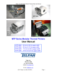
MTP-2232/2242 Modular Thermal Printer
MTP-2222 Printer without presenter
MTP-2200 Series Modular Thermal Printer
User Manual
TELPAR
A Platinum Equity COMPANY
187 Crosby Road
Dover, New Hampshire 03820
Toll Free: 800-872-4886 (from the U.S.A. and Canada only)
603-750-7237
Fax: 603-742-9938
Website: www.telpar.com
E-mail: [email protected]
Page 1 of 52
Warranty
TELPAR — Printer Limited Warranty
For one (1) year after shipment of the printer product to Buyer, Telpar warrants the product against defects in materials
and workmanship provided the product has been operated and maintained in accordance with manufacturer’s
operating and maintenance specifications. This warranty specifically excludes ribbons, paper and other consumable
items.
THIS WARRANTY IS IN LIEU OF ANY AND ALL OTHER WARRANTIES, EXPRESSED OR IMPLIED. TELPAR
MAKES NO OTHER WARRANTY AND BUYER SPECIFICALLY WAIVES ANY OTHER WARRANTIES, INCLUDING
WARRANTIES OF MERCHANTABILITY OR FITNESS FOR A PARTICULAR PURPOSE. THERE ARE NO
WARRANTIES THAT EXTEND BEYOND THOSE DESCRIBED HEREIN.
Telpar’s liability hereunder is limited to the repair or replacement of defective parts. This liability does not extend to
normal wear and tear. Telpar will, solely at its option, remedy all valid warranty claims either by:
(a)
Repairing or replacing the defective unit at Telpar’s factory; or
(b)
Repairing or replacing the defective subassembly at Telpar’s factory.
If so directed by Telpar, Buyer shall return the defective unit or subassembly, transportation prepaid by Buyer, to
Telpar’s factory. After repair or replacement has been accomplished, Telpar will return the unit or subassembly,
transportation prepaid by Telpar, to Buyer.
As a precondition to any warranty service, prior to return of any units or subassemblies to Telpar by Buyer, Buyer
must contact Telpar’s Order Administration Services and receive authorization in the form of a Return Material
Authorization (RMA) number. Telpar reserves the right to refuse any goods it has not previously authorized for return,
or any goods shipped without transportation prepaid.
No warranty shall apply to any damage resulting from or caused by Buyer, if Buyer shall make any changes,
modifications, additions or deletions of hardware, software or firmware in the Printer products sold hereunder without
Telpar’s advance written consent.
Warranty service may be obtained by contacting our Customer Service department for instructions:
TELPAR
187 Crosby Road
Dover NH 03820
ATTN.:
Warranty Service Department.
Telephone:
800-872-7237
Fax:
603-742-9938
Email:
[email protected]
Upon inspection, Telpar will make necessary repairs or replacement and return the merchandise, shipping prepaid.
Page 2 of 52
Table of Contents
1
General................................................................................................................................... 6
1.1
Applications...................................................................................................................... 7
1.2
Standard Features........................................................................................................... 7
1.3
Options for the MTP-2200 Series.................................................................................. 8
1.4
General Specifications................................................................................................... 8
1.5
Safety / Agency Information............................................................................................ 8
1.6
Power Supply Requirements......................................................................................... 9
1.6.1
External Power Supply (supplied separately)..................................................................... 9
1.6.2
Voltage: 24 VDC ±5%.................................................................................................... 9
1.6.3
3-Pin Hosiden Connector on Printer for Power Supply Connection............................... 9
1.7
2
Telpar Roll Paper for MTP-2200 Series...................................................................... 10
Operator Instructions....................................................................................................... 11
2.1
Unpacking and Inspection............................................................................................ 11
2.2
Paper Loading................................................................................................................ 11
2.2.1
Side-Loading Roll.......................................................................................................... 11
2.2.2
Top Loading Roll........................................................................................................... 11
2.3
Paper Jam....................................................................................................................... 11
2.3.1
3
Head Up Lever.............................................................................................................. 12
Installation........................................................................................................................... 13
3.1
Self Test Mode (also Burn-in and Hex Dump modes)..................................................... 13
3.1.1
Self Test....................................................................................................................... 13
3.1.2
Factory Burn-in Mode.................................................................................................... 13
3.1.3
Hex Dump printing mode................................................................................................ 13
3.1.4
Continuous Factory Burn-in Mode................................................................................... 13
3.1.5
MTP-2242 Self Test Printout........................................................................................... 14
4
Interface Specifications................................................................................................... 15
Page 3 of 52
4.1
General........................................................................................................................... 15
4.1.1
Setting of DIP Switches................................................................................................. 15
4.1.1.1
DSW1 – DIP Switch.................................................................................................. 15
4.1.1.2
DSW2 – DIP Switch 2................................................................ 16
4.1.1.3
JP9 - Configuration straps.................................................................. 17
4.1.1.4
Other Strap Options...................................................................... 18
4.2
Control Codes and Control Sequences..................................................................... 19
4.2.1
General Usage Print Commands..................................................................................... 19
4.2.2
Descriptions of Commands............................................................................................ 24
4.2.2.1
Status commands........................................................... 24
4.2.2.2
Set Print Mode.......................................................... 25
4.2.2.3
Printer Reset............................................... 25
4.2.2.4
Telpar's Window Commands............................... 25
4.2.2.5
Language Monitor Information................................................ 25
4.2.2.6
Bit Image (BI) Graphics Mode Commands............................................... 26
4.2.2.7
Print Bar Code Command................................................................ 26
4.2.2.8
Bar Code 128 definitions................................................................... 27
4.3
Serial (RS-232C) Interface............................................................... 29
4.3.1
Serial (RS-232C) Interface Specification.......................................................................... 29
4.3.2
Serial I/O Connector...................................................................................................... 29
4.3.3
Flow Control................................................................................................................. 30
4.4
Parallel Interface (IEEE-1284)...................................................................................... 30
4.4.1
Parallel I/O Connector, IEEE-1284 Type C....................................................................... 30
4.4.2
Alternate Parallel I/O Connector, IEEE-1284 Type A or B............... 32
5
Detailed Specifications.............................................................. 33
5.1
Detailed Specifications................................................................................................. 33
5.2
Error Detection Function.............................................................................................. 33
Page 4 of 52
5.3
Character Sets - Print Samples................................................................................... 35
5.4
MTP-2222 Dimensional Drawings................................................................................ 40
5.5
MTP-2232/MTP-2242 Dimensional Drawings............................................................. 41
5.6
Dimensional Drawings With Presenter....................................................................... 43
6
CE Declaration of Conformity........................................................................................ 46
List of Figures
Figure 1 - 3-Pin Hosiden Power Supply Connector............................. 9
Figure 2 - MTP-2242 with Cutter Mechanism closed............................. 12
Figure 3 - MTP-2242 with Cutter Mechanism open................................ 12
Figure 4 - MTP-2242 Self Test Printout................................ 14
Figure 5 - General Usage Print Commands......................................... 23
Figure 6 - Serial I/O Connector....................................................... 29
Figure 7 - Serial Interface RS-232C......................................... 29
Figure 8 - Parallel I/O Connector......................................... 30
Figure 9 - Code Page 437 Print sample............................... 35
Figure 10 - Code Page 850 Print sample.................................. 35
Figure 11 - Code Page 860 Print sample............................. 36
Figure 12 - Code Page 863 Print Sample....................................... 36
Figure 13 - Code Page 865 Print Sample............................. 37
Figure 14 - Code Page WPC1252 Print sample.............................. 37
Figure 15 - Code Page 858 Print sample.................................... 38
Figure 16 - International Character Sets............................... 39
Figure 17 - MTP-2222 Left Side View.................................. 40
Figure 18 - MTP-2222Top View........................................................ 40
Figure 19 - MTP-2222 Right Side View...................................................... 41
Figure 20 - MTP-2232/MTP-2242 Dimensional Drawing with Mounting Holes (Top View)........... 41
Figure 21 - MTP-2232/MTP-2242 Dimensional Drawing (Side View)................. 42
Page 5 of 52
Figure 22 - MTP-2232/2242 Isometric Drawing................. 42
Figure 23 - MTP-2222 with Presenter..................................................... 43
Figure 24 - MTP-2232 with Presenter................................................. 44
Figure 25 - MTP-2242 with Presenter.......................................... 45
Page 6 of 52
List of Tables
Table 1 - Current (A) for Printer Head.............................. 9
Table 2 - Peak Current for Motor.............................. 9
Table 3 - DIP Switch 1 (DSW1) Settings.......................................... 15
Table 4 - DIP Switch 2 (DSW2) Settings.............................. 16
Table 5 - Configuration strap Settings............................... 17
Table 6 - Other Strap Options..................................... 18
Table 7 - First Status byte transmitted (and MASK for DLE A command)................ 24
Table 8 - Printer's response to a STATUS REQUEST command......... 24
Table 9 - Set Print Mode Table.............................................. 25
Table 10 - Serial (RS-232C) Interface Specification............. 29
Table 11 - Serial (RS-232C) Interface Pin Assignments.............. 30
Table 12 - Parallel Interface Pin Assignments - IEEE-1284 Nomenclature............... 31
Table 13 - Parallel Interface Pin Assignments - Centronics nomenclature.......... 32
Table 14 - General Specifications........................... 33
Table 15 - Error Detection Functions................................. 34
1
General
The MTP-2200 series of modular thermal printers is designed specifically for the high performance, size and durability
requirements of cut and drop (or cut and present with optional Document Presenter ) applications. The compact size
and high performance characteristic, coupled with its rugged design, makes it ideal for the kiosk environment.
These models make up the MTP-2200 Series covered in this manual:
·
MTP-2222 SP - 60 mm (2.36 in) paper width
·
MTP-2232 SP - 85 mm (3.35 in) paper width .
·
MTP-2242 SP - 114 mm (4.49 in) paper width .
·
OPTIONS include:
-P = with Document Presenter.
F5 = with 512 Kbytes of FLASH memory.
P1 = with 1 Mbyte of PAGE RAM memory.
1.1
Applications
·
·
·
·
Kiosks
Automated Teller Machines (ATMs)
Parking ticket dispensing
Gaming receipts
1.2
Standard Features
Page 7 of 52
·
·
·
·
·
·
·
·
·
·
·
Direct thermal printing
Interfaces : Serial or parallel
Auto Cutter : full cut/partial cut under software control is standard
All metal construction
Adjustable paper low sensor
Paper auto load function
Ò
ESC/POS [1] The commands conform to ESC/POS
Print speed of up to 80 mm/sec (3.1 in/sec); 640 dot lines/second)
LEDs visible and DIP switches accessible without removing cover
Paper capacity : 152 mm (6 in) diameter roll with 50 mm diameter core
Overall size including 152 mm (6 inch) diameter roll of paper :
• MTP-2222:
163 mm x 115 mm x 231 mm(6.4"H X 4.5"W X 9.1"D)
• MTP-2232/2242:
163 mm x 170 mm x 231 mm(6.4"H X 6.7"W X 9.1"D)
·
International character set : U.S.A., France, Germany, England, Denmark (2 choices), Sweden, Italy, Spain (2
choices), Japan, Norway, Latin America and Korea
·
Barcode embedded symbologies: UPC-A, UPC-E, EAN 13, EAN 8, 3of 9. ITF, CODABAR, and Code 128
·
Two resident font sizes
·
Code pages 437, 850, 858, 860, 863, 865, and WPC 1252.
·
Bit image mode
·
Reverse video mode
·
Black mark sensing (TOF mode)
1.3
·
•
•
•
·
·
·
·
1.4
·
·
·
·
·
·
·
·
1.5
Options for the MTP-2200 Series
Paper width :
60 mm (2.36 in) – MTP-2222
85 mm (3.35 inch) – MTP-2232
114 mm (4.49 in) – MTP-2242
®
®
Microsoft Windows driver [2]
Document Presenter (-P option)
FLASH memory , 512Kbytes (F5 option)
PAGE memory (RAM), 1Mbyte (P1 option)
General Specifications
Resolution : 8 dots/mm (203 dots/in)
Paper thickness : 0.06 mm to 0.10 mm maximum (.0024 in to .0039 in)
o
o
o
o
Operating temperature : 5 C to 40 C (41 F to 104 F)
o
o
o
o
Storage temperature : -20 C to 60 C (-4 F to 140 F)
Operating humidity : 20-85% RH (non-condensing)
Weight : Standard configuration without paper 2.0 kg (4.5 lbs.)
Expected life of mechanism: 50 km minimum due to wear
5
5
Expected life of cutter: 3 x 10 cuts for the MTP-2242, 5 x 10 cuts for the MTP-2222 and MTP-2232
Safety / Agency Information
Information Technology Equipment IEC 950
Product Safety: UL 1950 / EN60950
EMC:
CFR47 / Part 15 / EN55022
File Number:
188263
Project:
00NK40431
Page 8 of 52
1.6
1.6.1
Power Supply Requirements
External Power Supply (supplied separately)
Use a Listed/Certified Power Supply.
Follow local wiring codes for external wiring.
1.6.2
Voltage : 24 VDC ±5%
No requirement for external 5 VDC power supply, the 5 VDC for logic is supplied from the 24 VDC, by a regulator
internal to the printer.
This printer prints using high speed currents at a low duty cycle. Typically, a switching power supply rated at 24 Volts
DC. 2 Amps is all that is needed as long as the power supply does not have too much over current protection.
Current (A) for Printer Head
Printing Printer
Avg
Peak
rate
Model
Solid
MTP-2222
1.75
4
Black-out MTP-2232
2.25
5
MTP-2242
3
7
Typical
MTP-2222
1
2.5
ASCII text MTP-2232
1.25
2.5
MTP-2242
1.5
3.5
Table 1 - Current (A) for Printer Head
Current (A) for Motor
Peak = 1.0 A, typical = <0.1 A
Table 2 - Peak Current for Motor
1.6.3
3-Pin Hosiden Connector on Printer for Power Supply Connection
Power Connector::
Hosiden #TCS7960-53-2010
Mating Connector:
Hosiden #TCP8927-53-1100 or
TCP8927-63-1110
Figure 1 - 3-Pin Hosiden Power Supply Connector
1.7
Telpar Roll Paper for MTP-2200 Series
Thermal sensitive coating is on the “inside” of the roll.
·
For MTP-2222: 152 mm (6 in) outside diameter, 60 mm (2.36 in) wide, approximate length 180 m (590 ft) P/N
251410-0602
·
For MTP-2232 152 mm (6 in) outside diameter, 85 mm (3.35 in) wide, approximate length 180 m (590 ft) P/N
251102-1603
·
For MTP-2242 152 mm (6 in) outside diameter, 114 mm (4.49 in) wide, approximate length 180 m (590 ft) P/N 251410-0604
Page 9 of 52
Specific to Thermal Printers: TELPAR does not warranty damages to the thermal print head as a result of printing
with thermal paper not specified or approved by TELPAR
2
Operator Instructions
2.1
Unpacking and Inspection
Carefully unpack and inspect your MTP-2200 for any damage that may have occurred in transit. Should any damage
have occurred, notify TELPAR, save the shipping carton and packing materials , and file a damage claim with the
carrier. Specify the nature and the extent of the damage. Before installing or operating the printer, check the following:
·
Printer mechanism and paper path are clear of all packing materials or other foreign matter.
·
Paper is installed. DO NOT OPERATE the printer without paper. Refer to Section 2.2 - Paper Loading for paper
loading instructions.
2.2
2.2.1
Paper Loading
Side-Loading Roll
The MTP-2222 printer is configured as a side-loading printer . Slide roll of paper over spindle with paper fed off the
bottom toward the paper slot (front of unit).
To load paper , turn on the power and feed the straight edge of the paper into the paper guide. Inserting paper will
result in the automatic loading of paper once it is fed into the paper guide
Ensure that the paper is installed correctly and feeding properly with the thermal side facing up.
2.2.2
Top Loading Roll
The MTP-2232 and MTP-2242 printers are configured as a drop in loader . Load the roll of paper by placing the
spindle inside the roll of paper and place spindle in slots with paper fed off the bottom toward the paper slot (front of
unit).
To load paper , turn on the power and feed the straight edge of the paper into the paper guide. Inserting paper will
result in the automatic loading of paper once it is fed into the paper guide.
Ensure that the paper is installed correctly and feeding properly with the thermal side facing up.
2.3
Paper Jam
In the event of a paper jam condition do not force paper into the unit, or try to pry the paper out of the unit, this may
damage the thermal print mechanism . Caution should be exercised when working next to the cutter mechanism , the
blades are sharp and may cause serious injury.
To release paper:
·
Move Head Up lever to right of Advance wheel to top position
·
Lift cutter mechanism to “Open position (See - MTP-2242 with Cutter Mechanism open ) Paper can be
removed at this time. Once paper is cleared from the mechanism, return the cutter assembly to its home position.
Models MTP-2222 , MTP-2232 and MTP-2242 all operated similarly
·
Move Head Up lever to right of Advance wheel to the bottom position to return to printing position
2.3.1
Head Up Lever
The Head Up lever is located by the Paper Feed knob . The down position is ready to print. The middle position
reduces pressure between the printhead and the print platen roller for easier manual feeding. The up position lifts the
printhead off of the platen roller for manually inserting paper or for clearing a paper jam. Both the middle and up
positions signal the microprocessor that the head is up so that no printing will occur.
Page 10 of 52
Figure 2 - MTP-2242 with Cutter Mechanism closed
Figure 3 - MTP-2242 with Cutter Mechanism open
3
Installation
3.1
Self Test Mode (also Burn-in and Hex Dump modes)
The MTP-2200 series has a self-test mode that will print and cut a sample document. All electrical and mechanical
portions of the printer are exercised and checked by this action, except for the serial interface or parallel interface
components. The self-test printout also shows pertinent information pertaining to operation of the printer.
3.1.1
Self Test
To place the unit into self-test mode : turn the power switch off, press and hold the FEED push button switch and place
the POWER switch in the ON position, then release the paper feed switch. See Figure 4 - MTP-2242 Self Test
Printout for examples of the self-test printout.
3.1.2
Factory Burn-in Mode
If the paper feed button is held for 4 seconds after power is turned on, the printer will enter the Factory Burn-In Mode.
A hundred shorter sheets will be printed.
Page 11 of 52
3.1.3
Hex Dump printing mode
If the paper feed button is held for 8-12 seconds after power is turned on, the printer will enter the Hex Dump Mode.
All codes received will be printed in HEX format rather than causing the normal execution, this may be useful for
troubleshooting applications.
3.1.4
Continuous Factory Burn-in Mode
If the paper feed button is held for 12 seconds after power is turned on, the printer will enter the CONTINUOUS
Factory Burn-In Mode that does not stop after 100 sheets are printed.
Page 12 of 52
3.1.5
MTP-2242 Self Test Printout
4
Interface Specifications
4.1
General
Page 13 of 52
The MTP-2200 Series may be configured to be a Serial RS-232 interface or an IEEE-1284 Parallel interface by DIP
Switch settings .
4.1.1
4.1.1.1
Setting of DIP Switches
DSW1 – DIP Switch
Item
Serial-interfacecommunication
baud rate setting
Parity selection
Parity use
Number of data
bits
Serial handshake
Interface
DIP Switch 1 (DSW1) Settings
Bit No
Setup status
Setup state
Factory
settings
Bit 1 Bit 2 Bit 3
Baud Rate
1,2,3 OFF
OFF
OFF
2400
19200
ON
OFF
OFF
4800
OFF
ON
OFF
9600
ON
ON
OFF
14.4K
OFF
OFF
ON
19.2K
ON
OFF
ON
28.8K
OFF
ON
ON
31.2K
ON
ON
ON
38.4K
4
OFF
Even
Even
ON
Odd
5
OFF
No parity
No parity
ON
Parity
8
6
OFF
8
ON
7
7
OFF
XON/XOF
DTR
ON
DTR
8
OFF
Serial
Parallel
ON
Parallel
Selection
Table 3 - DIP Switch 1 (DSW1) Settings
Page 14 of 52
4.1.1.2
DSW2 – DIP Switch 2
Item
Top of Form
sensor
Purge setting
DIP Switch 2 (DSW2) Settings
Setup Status
Setup State
Bit No
1
OFF
ON
OFF
ON
2
3, 4, 5, 6
Reserved
7
Reserved
8
3
OFF
ON
OFF
ON
OFF
ON
OFF
ON
OFF
ON
OFF
ON
OFF
ON
OFF
ON
4
OFF
OFF
ON
ON
OFF
OFF
ON
ON
OFF
OFF
ON
ON
OFF
OFF
ON
ON
5
OFF
OFF
OFF
OFF
ON
ON
ON
ON
OFF
OFF
OFF
OFF
ON
ON
ON
ON
6
OFF
OFF
OFF
OFF
OFF
OFF
OFF
OFF
ON
ON
ON
ON
ON
ON
ON
ON
Disabled
Enabled
Retract
Eject
Intl Char / Code Page
USA / CP437
France / CP858
Germany / CP858
England / CP858
Denmark / CP858
Sweden / CP858
Italy / CP858
Spain / CP858
Japan / CP850
Norway / CP865
Denmark 2 / CP858
Spain 2 / CP858
Latin America / CP437
Korea / CP850
Reserved
Reserved
Table 4 - DIP Switch 2 (DSW2) Settings
Page 15 of 52
Factory
settings
Disabled
Retract
USA /
CP437
4.1.1.3
JP9 - Configuration straps
JP9 - Configuration straps
Strap#
1
Name
Erase FLASH
ON
OFF
ON
OFF
3
ON
OFF
4
Paper Low
ON
OFF
5
Cutter
ON
OFF
6
Document
ON
Presenter
OFF
7
ON
OFF
8
ON
OFF
Table 5 - Configuration strap Settings
Erase optional FLASH memory when
power is turned on.
No affect on FLASH.
2
Paper Low sensor is installed.
Paper Low sensor is not installed.
Cutter is installed.
Cutter is not installed.
Presenter is installed.
Presenter is not installed.
Page 16 of 52
4.1.1.4
Other Strap Options
Other Strap Options
Location Name
Position
Description
JP1
FLASH size
A20
4 Mbit (256K x16) optional FLASH is installed
unmarked
8 Mbit (512K x16) optional FLASH is installed
JP2
EPROM size unmarked
< 256K x 8 EPROM installed
256K
=> 256 x 8K EPROM installed
JP3
EPROM size unmarked
<1M x 8 EPROM installed
1M
1M x 8 EPROM installed
JP4
EPROM size unmarked
< 512K x 8 EPROM installed
512K
=> 512K x 8K EPROM installed
JP5
System RAM 32
32K x 8 RAM installed
size
512
512K x 8 RAM installed
JP6
EPROM size 32
32K x 8 EPROM installed
128
=> 128K x 8 EPROM installed
JP7
FLASH option WP
Optional FLASH is Write Protected
unmarked
Optional FLASH can be overwritten
JP8
FLASH option BBL
Boot Block of optional FLASH is locked
Unmarked
CAUTION – Boot block can be overwritten
JP9
Configuration
See previous section
JP10
Test points
Factory use only
JP11
Serial port
Factory use only
JP12
Boot function BF
Boot up to FLASH
BR
Boot up to ROM
JP13
Optional
Unmarked
Install if JP9 is set to BF
FLASH
OFF
Install if JP9 is set to BR
JP14
LED2
ON
Connect drive signal to LED2 and J10 pin 4
OFF
LED2 and J10 pin 4 have no drive signal
JP15
Buzzer
ON
Connect drive signal to BUZZER and J10 pin 2
OFF
BUZZER and J10 pin 2 have no drive signal
JP16
Connect LED2 Install ONLY if either JP11 or JP12 (but not both) are installed.
and BUZZER
Table 6 - Other Strap Options
Page 17 of 52
4.2
Control Codes and Control Sequences
4.2.1
General Usage Print Commands
Name
General Usage Print Commands
Command Command
ASCII
HT
Tab
Description
hex
Move the print position to
the next horizontal tab
position. See ESC D. If a
TAB is received and there
are no more tab positions
set on the current line, the
TAB command is ignored. If
the TAB will exceed the
right margin, an auto-print
is performed and the print
position is set to the start of
the next line.
LF
0A
Data on the current line is
printed, paper is fed one
line based on the current
line spacing, and the print
position is set to the left
margin. If the current line
spacing is set to less than
the current font height then
paper is fed to print the
current font height (see
ESC 2, ESC 3 +n, and ESC
C +n).
FF
0C
Feed paper to end of page
as defined by the default
page length of 11 inches or
as modified by the US C
command. If TOF mode is
enabled (DIP switch 2
position 1 or ESC c 1 +n))
then paper is fed until the
next BLACK MARK is
detected. To advance to
the BLACK MARK if TOF
mode is not enabled use
the GS FF command.
DLE
10
Data Link Escape
Sequence Header.
DLE A +n1 10 41 +n1 +n1 and +n2 define a mask
+n2
+n2
to enable the transmission
of the STATUS bytes when
a user defined event
occurs. See Section 4.2.2.1
- Status commands .
Default = 00 00 (ASB
disabled).
Line feed
Form Feed
DLE
Enable Auto Status Back
Page 18 of 52
09
Buffered STATUS request
DLE B
The STATUS bytes are
transmitted when this
command is processed out
of the receive buffer. See
Section 4.2.2.1 - Status
commands .
DLE R
10 52
The STATUS bytes are
transmitted when this
command is received by
the printer. See Section
4.2.2.1 - Status commands
.
DLE U +n1 10 55 +n1 When DLE U +n1 +n2 is
+n2
+n1
processed out of the
receive buffer, the printer
will transmit DLE U +n1 +n2
back to the host.
ESC
1B
ESCAPE Sequence
Header.
GS
1D
GROUP SEPARATOR
Sequence Header.
US
1F
UNIT SEPARATOR
Sequence Header.
ESC RS
1B 1E
Printing is reversed to white
characters on black
background. Reverse video
requires more power to
print and is less readable.
(Same as GS B 01).
Real time STATUS request
User selected data string
ESC
GS
US
Reverse Video ON
Name
Reverse
Video OFF
Set Print
mode
Command Command
ASCII
ESC US
ESC ! +n
ESC \ +m
Select Bit
Image mode +n1 +n2
+d1~dn
Underline
ESC - +n
Set 1/6” line
spacing
ESC 2
Description
hex
1B 1F
Printing is set to default
mode of black print on
white background. (Same
as GS B 00).
1B 21 +n Set Print mode = font A or
B, Double high, Double
wide. See Section 4.2.2.2 Set Print Mode .
1B 2A +m Select Bit Image mode. +m
+n1 +n2 = ?. n2*256 + n1 =
(data)
Number of DOT LINES of
data to follow. (data) = the
amount of data required to
complete the sequence.
Telpar does not fully
support this command.
Please refer to US *
command which follows.
1B 2D +n Bit 0 of n = 0 turns
underlining OFF. Bit 0 of n
= 1 turns underlining ON.
Default is OFF.
1B 32
Set 1/6 inch line spacing.
Page 19 of 52
10 42
Set Line feed ESC 3 +n
pitch
1B 33 +n
Printer reset
ESC @
1B 40
Set page
length
ESC C +n 1B 43 +n
Set Horizontal ESC D
Tab positions +d1~dn
NUL
1B 44
(data) 00
Forward
ESC J
paper feed for +n
n dot lines
1B 4A +n
Select
ESC R
International +n
character set
1B 52 +n
Select
justification
for bar code
1B 61 +n
ESC a +n
Set line spacing to n dot
lines. If the n specified is
less than the height to print
text using the currently
selected character set then
printing will cause enough
paper feeds to print the
entire line but a print
command with no data in
the buffer will cause paper
to feed by this amount.
Default is 1/8 inch
Initialize. See Section
4.2.2.3 - Printer Reset .
Set page length to n
character lines using the
current font. Overwrites the
page length defined by US
C.
Set from 1 to 32 tab
positions in the current
character size. Data values
range from 1 to 255 in
ascending order. The NUL
character (00 hex)
terminates this command if
less than 32 tab settings
are being set. If a data
value is less than the
previous data value, this
command is terminated.
ESC D NUL clears all tab
positions. Default is every 8
columns. Print after a tab
starts in the column
following the tab setting
specified.
Feed paper n dot lines. If
there is data in the buffer, it
is printed and paper is fed
the difference of the +n and
the amount needed to print
the data. Range = 0 to 255
dec.
Select international
character set. Range = 0
through 15 dec. See Figure
16 - International Character
Sets for characters affected
for each character set.
n=00hex, left justify.
n=01hex, center justify.
n=02hex, right justify. GS L,
GS W, and ESC \ will also
affect the bar code
justification.
Page 20 of 52
Name
Command Command
ASCII
Select paper ESC c 1
type
+n
hex
1B 63 31
+n
Paper sensor
to output PE
signal
Paper sensor
to stop
printing
Select CODE
PAGE
ESC c 3
+n
1B 63 33
+n
ESC c 4
+n
1B 63 34
+n
ESC t +n
1B 74 +n
Description
Bit 0 = 0, Normal paper.
Bit 0 = 1, TOF (Black Mark
sensor) enabled. Default is
based on Dip switch 2
position 1.
Command is not
implemented, all four bytes
will be ignored.
Command is not
implemented, all four bytes
will be ignored.
n = 0, code page 437
(standard USA).
n = 2, Code page 850
(Multilingual).
n = 3, Code page 860
(Portuguese).
n = 4, Code page 863
(Canadian-French).
n = 5, Code page 865
(Nordic);
n=10 hex, WPC1252;
n=13 hex, Code page 858
Feed to Top
of Form
GS FF
1D 0C
Select
GS !
character size
1D 21 +n
Reverse
video
1D 42 +n
GS B +n
(Multilingual with Euro
character)
If TOF mode is disabled
(DIP switch 2 position 1 or
ESC c 1 +n) then paper is
fed until the trailing edge of
the Black Mark sensor is
detected, the current page
length is reached, or the
printer runs out of paper.
Bits 7,6,5,4 for width, Bits
3,2,1,0 for height. Can
select 1,2,4, or 8 times
normal size. 0hex = 1X
size, 1hex = 2X size, 2hex
= 4X size, and 3hex = 8X
size.
Bit 0 of n = 1 causes
Reverse Video to be
printed (same as ESC RS).
Bit 0 of n = 0 turns Reverse
Video off (same as ESC
Page 21 of 52
HRI position
US).
Select HRI printing position
for bar codes, n = 00hex
no HRI printed. n = any
value other than 00hex,
HRI printed below the bar
code.
GS L +nH 1D 4C +nH Sets the left margin to
+nL
+nL
nH*256 + nL dot positions
from the left side of the
print head. Default = 0
(leftmost dot). The value
being set must be equal to
or less than the right
margin minus 80 dots. If the
margin is set to any invalid
value this command is
ignore. Range = 0 to Right
Margin - 80.
GS V +n 1D 56 +n If n = 0 (either 00hex or
+m
+m
30hex) a full cut is
performed and the +m byte
is not needed. If n = 1
(either 01hex or 31hex) a
partial cut is performed and
the +m byte is not needed.
If n is a capital A (41hex)
then paper is fed for m dot
lines and then a full cut is
performed. If n is a capital
B (42hex) then paper is fed
for m dot lines and then a
partial cut is performed. If a
presenter is installed, only
full cuts are performed.
Description
Command Command
GS H +n
1D 48 +n
Set Right
Margin
ASCII
GS W +
nH + nL
HRI font
GS f
hex
10 57 + nH Set the right margin to
+ nL
nH*256 + nL dot positions
from the left side of the
print head. Default =
maximum dot count for the
printer mechanism minus 1.
The value being set must
be equal to or greater than
the left margin plus 80 dots.
If the margin is set to any
invalid value this command
is ignore. Range = Left
Margin +80 to rightmost
dot.
1D 66 +n Not implemented, the
controller selects a font and
size to best fit under the bar
code being printed.
[1D 68 +n Set the bar code height in
Set left
margin
Paper cut
Name
Set Bar code GS h +n
Page 22 of 52
height
Bar code
printing
GS k +m [1D 6B +m
+n +d1~dn +n (DATA)]
Set Bar code GS w +n
magnification
[1D 77 +n]
Bit image
command
US * +nH 1F 2A +nH
+nL +data +nL +data
Set Page
Length
US C +nH 1F 43 +nH
+nL
+nL
Eject/retract
ticket
US E
1F 45 +n
Set timeout to US K
use before an
untaken ticket
is purged
1F 4B +n
Global IEEE- US S +n
1284
STATUS
Enable /
Disable
1F 53 +n
Name
Start of
Document for
Command Command
ASCII
US b
hex
1F 62
dots. Default = 64. Range 1 to 255 dec.
Selects the bar code type
and prints. See Section
4.2.2.7 – Print Bar Code
Command .
Set the width of the bars
used to print bar codes.
The width of a narrow bar is
set to n. Range = 1 to 8.
Default = 2. A setting of
n=1 prints a bar code so
small it is possibly not
readable..
256*nH +nL defines how
many bytes of bit image
data will follow. See
Section 4.2.2.6 - Bit Image
(BI) Graphics Mode .
Sets the page length to
256*nH +nL dot lines.
Default is 11 inches.
Overwrites the page length
set by ESC C.
Bit 0 of n = 0 sets the mode
to RETRACT an untaken
ticket back into the printer.
Bit 0 of n = 1 sets the mode
to EJECT an untaken ticket
out the front of the printer.
See DIP SWITCH 2
position 2 for the default.
If a document is cut and
presented (but not
removed) and another
document is sent to the
printer, the first document
will not be purged (either
Ejected or Retracted) until
+n seconds after the first
document is presented.
Default is 5 second.
Low order nibble of +n = 0
disables all STATUS
transmissions in IEEE-1284
parallel mode. Low order
nibble of +n = 1 thru F
enables STATUS
transmission. Default is
disabled. See Section
4.2.2.1 - Status commands
.
Description
Used only by Telpar's
Windows drivers. See
Page 23 of 52
WINDOWS
Section 4.2.2.4 - Telpar's
Window Commands.
End of
US e
1F 65
Used only by Telpar's
Document for
Windows drivers. See
WINDOWS
Section 4.2.2.4 - Telpar's
Window Commands.
Set horizontal US x +nH 1F 78 +nH The horizontal print position
Print Position +nL
+nL
is set to (256*nH + nL) * 8
dots from the left margin.
See Section 4.2.2.6 - Bit
Image (BI) Graphics Mode .
Set Relative US y +nH 1F 79 +nH Causes paper to feed
Vertical move +nL
+nL
256*nH + nL dot lines. See
Section 4.2.2.6 - Bit Image
(BI) Graphics Mode
Commands .
Set Horizontal US A
1F 41
Sets the x-move function
Print Position
(see US x +nH +nL) to be a
ABSOLUTE
move relative to the left
margin. See US R.
Set Horizontal US R
1F 52
Sets the x-move function
(see US x +nH +nL) to be a
Print Position
RELATIVE
move relative to the current
position. Default setting.
See US A.
Figure 5 - General Usage Print Commands
Page 24 of 52
4.2.2
4.2.2.1
Descriptions of Commands
Status commands
All transmission of status in IEEE-1284 mode is disabled at power on. Status transmission must be enabled by the US
S +n command before any STATUS transmission will occur in IEEE-1284 mode.
In case of an ERROR as defined in the table below, the printer transmits DLE E and the 2 status bytes. The response
to a STATUS REQUEST is to transmit DLE (10hex) followed a SOURCE byte that distinguishes what type of status is
being transmitted followed by the two status bytes as defined in the table below.
The SOURCE byte is defined as:
A = Auto Status Back . Is disabled by default but is enabled when the printer receives the DLE A +n1 +n2 command.
+n1 and +n2 define a mask using the same byte/bit structure as in the table below. A "1" in a bit position enables the
automatic transmission of DLE A and the 2 status bytes when an enabled condition occurs. The bit positions marked
as errors in the table will always cause the automatic transmission of DLE E and the 2 status bytes so these positions
will usually be "0" in the user defined mask.
B = Buffered status . DLE B and the 2 status bytes are transmitted when the DLE B command is processed out of the
input buffer.
R = Real Time Status . If enabled by US R +n command, DLE R and the 2 status bytes are transmitted immediately
when the DLE R command is received by the printer.
U = not a true STATUS request. When DLE U +n1 +n2 is processed out of the receive buffer, the printer transmits
DLE U +n1 +n2 back to the host. The user can send DLE U +n1 +n2 anywhere within a document if he needs to know
that the printer has processed the document up to that point.
First Status byte transmitted (and MASK
for DLE A command)
Bit Type
Function/condition
7
Status
Spare
6
Status
Spare
5
Status
Receive buffer is full
4
ERROR Cutter Error
3
Status
Printer Busy
2
Status
Receipt Taken
1
Status
Receipt Dropped
0
ERROR Delivery Jam
Table 7 - First Status byte transmitted (and MASK for DLE A command)
Second Status byte transmitted (and MASK
for DLE A command)
Bit
Type
Function/condition
7
Status
Spare
6
Status Print head over temperature
5
Status
Spare Sensor
4
Status
Paper Low
3
Status
Cutter Home
2
Status
Paper at Delivery
1
ERROR
Paper Out
0
ERROR
Head Up
Table 8 - Printer's response to a STATUS REQUEST command
Page 25 of 52
4.2.2.2
Set Print Mode
ESC ! +n
[1B 21 +n]
+n is defined as:
Bit 7--- Not used.
Bit 6 --- Not used.
Bit 5 --- 0 = Double high print OFF.
1 = Double high print ON.
Bit 4 --- 0 = Double wide print OFF.
1 = Double wide print ON.
Bit 3 --- Not used.
Bit 2 --- Not used.
Bit 1 --- Font size.
Bit 0 --- Font size.
Set Print Mode Table
Bit 1
Bit 0 Font size (WxH)
0
0
FontB (10x30)
0
1
FontA (12x30)
Table 9 - Set Print Mode Table
Both double wide and double high can be selected for either character size. When a printed line contains characters
with different heights, the characters are arranged so that the baseline of all characters lines up. Default = 00hex (Font
B, 10 x 30 matrix) for MTP-2222. Default = 01hex (Font A, 12 x 30 matrix) for MTP-2232 and MTP-2242
4.2.2.3
Printer Reset
ESC @ [1B 40]
Initializes the printer.
Any data received before the ESC @ but not yet printed is cleared. The character size is set to the default font. The
DIP Switch setting sets international character set. Left and Right Margins are set to the defaults. Reverse video is
turned off. Underline printing is turned off. Bar code height is set to 64. Bar code magnification is set to 2.
4.2.2.4
Telpar's Window Commands.
use of device fonts for print speed enhancement, the Begin Document (US b) and End Document (US e) commands
were created for use by the Telpar Windows driver. These two commands should not be sent to the printer by any
other application program since unexpected results will occur.
4.2.2.5
Language Monitor Information
Not available at publication date
Page 26 of 52
4.2.2.6
Bit Image (BI) Graphics Mode Commands
BI
US * +nH +nL +data
1F 2A +nH +nL +data
256*nH +nL defines how many bytes of bit image data will follow. The data is received sequentially with the first byte
representing the first 8 dot positions at the top left side of the bit image with bit 7 being to the left and bit 0 being to the
right as printed.
XMOVE
US x +nH +nL
1F 78 +nH +nL
The horizontal print position is set to (256*nH + nL) * 8 dots from the left margin.
If there is a lot of white space on the current dot line, the XMOVE command can cause the print location pointer to be
moved resulting in less data required to define a dot line of bit image data to be printed. Anytime there is more than 4
bytes of white space (32 dots) the XMOVE command will result in less data being sent to the printer. Another BI
command can follow the XMOVE command until a YMOVE signifies the end of the current dot line.
YMOVE US y +nH +nL
1F 79 +nH +nL
Causes paper to feed 256*nH + nL dot lines. This is also the BI line terminator and print command.
4.2.2.7
Print Bar Code Command
GS k +m +n +d1~dn
[1D 6B +m +n (DATA)]
+m selects the bar code type. +n defines the number of data bytes which follow.
If more data is sent than can fit on the printer being used, the bar code is not printed.
+m
Bar code
+n
Valid data
comment
41
UPC-A
11
0-9
Checksum generated & printed
42
UPC-E
7
0-9
Checksum generated & printed
43
EAN13
12
0-9
Checksum generated & printed
44
EAN8
7
0-9
Checksum generated & printed
45
Code39
variable
0-9 A-Z sp $%*-./
46
ITF
variable.
0-9
If an odd number of data bytes is sent, a leading
zero will be added.
47
CODABAR variable.
0-9 - $ : / . +ABCD
49
CODE128
variable.
See Section 4.2.2.8 - Bar Code 128 definitions
74
CODE 39
variable.
0-9 A-Z sp $%*-./
Checksum generated & printed
75
ITF
variable.
0-9
Checksum generated & printed. If the data sent
and the checksum causes an odd number of
digits, a leading zero will be printed.
Page 27 of 52
4.2.2.8
Bar Code 128 definitions
Code128 Character set: 103 data chars, three different start characters, and a unique stop character.
CodeA consists of the ASCII characters 00hex thru 5Fhex, FNC1 thru FNC4, Shift, CodeB, and CodeC.
CodeB consists of the ASCII characters 00hex thru 7Fhex, FNC1 thru FNC4, Shift, CodeA, and CodeC.
CodeC consists of 2 digit numeral characters 00dec thru 99dec, FNC1, CodeA, and CodeB.
The 103 different bar code patterns have different meanings depending on whether CodeA, CodeB, or CodeC was
specified when the data was received. The data string must start with {A or {B or {C to specify CodeA, CodeB, or
CodeC. A checksum is calculated and printed by the printer.
Value used to CodeA CodeB CodeC
Value used to CodeA
CodeB
CodeC
calculate
calculate
checksum
checksum
0
(sp)
(sp)
00
54
V
V
54
1
!
!
01
55
W
W
55
2
"
"
02
56
X
X
56
3
#
#
03
57
Y
Y
57
4
$
$
04
58
Z
Z
58
5
%
%
05
59
[
[
59
6
&
&
6
60
\
\
60
7
'
'
07
61
]
]
61
8
(
(
08
62
^
^
62
9
)
)
09
63
_
_
63
10
*
*
10
64
00hex
`
64
11
+
+
11
65
01hex
a
65
12
,
,
12
66
02hex
b
66
13
13
67
03hex
c
67
14
.
.
14
68
04hex
d
68
15
/
/
15
69
05hex
e
69
16
0
0
16
70
06hex
f
70
17
1
1
17
71
07hrx
g
71
18
2
2
18
72
08hex
h
72
19
3
3
19
73
09hex
i
73
20
4
4
20
74
0Ahex
j
74
21
5
5
21
75
0Bhex
k
75
22
6
6
22
76
0Chex
l
76
23
7
7
23
77
0Dhex
m
77
24
8
8
24
78
0Ehex
n
78
25
9
9
25
79
0Fhex
o
79
26
:
:
26
80
10hex
p
80
27
;
;
27
81
11hex
q
81
28
<
<
28
82
12hex
r
82
29
=
=
29
83
13hex
s
83
30
>
>
30
84
14hex
t
84
31
?
?
31
85
15hex
u
85
32
@
@
32
86
16hex
v
86
33
A
A
33
87
17hex
w
87
34
B
B
34
88
18hex
x
88
35
C
C
35
89
19hex
y
89
36
D
D
36
90
1Ahex
z
90
37
E
E
37
91
1Bhex
{
91
38
F
F
38
92
1Chex
|
92
Page 28 of 52
39
G
G
39
93
1Dhex
}
93
40
H
H
40
94
1Ehex
~
94
41
I
I
41
95
1Fhex
DEL
95
42
J
J
42
96
FNC3
FNC3
96
43
K
K
43
97
FNC2
FNC2
97
44
L
L
44
98
SHIFT
SHIFT
98
45
M
M
45
99
CodeC
CodeC
99
46
N
N
46
100
CodeB
FNC4
CodeB
47
O
O
47
101
FNC4
CodeA
CodeA
48
P
P
48
102
FNC1
FNC1
FNC1
49
Q
Q
49
50
R
R
50
51
S
S
51
52
T
T
52
53
U
U
53
Code128 Start Characters
Value used to calculate checksum
Data sent
represents
103
{A
Start character CodeA
104
{B
Start character CodeB
105
{C
Start character CodeC
Code128 Stop Character
106
Stop character
Code128, other two character data sequences: Note: Since { is used as a sequence header to specify special
characters, {{ must be sent as data to actually print { in the bar code.
Data sent
represents
Data sent
represents
{1
FNC1
{S
Shift
{2
FNC2
{{
{
{3
FNC3
{4
FNC4
4.3
4.3.1
Serial (RS-232C) Interface
Serial (RS-232C) Interface Specification
Serial (RS-232C) Interface Specification
Item
Specification
Data receive speed
Baud rate selected by DIP switch
Synchronizing method
Asynchronous, Full duplex
Handshake
DTR/DSR signal or XON/XOFF (selected by DIP
switch)
Input output level
RS-232C
Signal level
Space (logic=0) +3 V ~ +12 V
Mark (logic=1) -3 V ~ -12 V
Table 10 - Serial (RS-232C) Interface Specification
4.3.2
Serial I/O Connector
Page 29 of 52
Figure 6 - Serial I/O Connector
Page 30 of 52
Serial Interface RS-232C
Figure 7 - Serial Interface RS-232C
Serial (RS-232C) Interface Pin Assignments
Pin
Name
Direction
Function
2
RD
I
RS232 received data.
3
XD
O
RS232 transmitted data.
4
DTR
O
Hardware handshake line.
5
GND
Logic ground.
6
DSR
I
High (“space”) = OK for the printer to transmit
data when requested. The state of DSR is
IGNORED for XON/XOF handshaking if selected.
Table 11 - Serial (RS-232C) Interface Pin Assignments
4.3.3
Flow Control
The MTP-2200 series employs a 6 K byte data buffer to allow the host computer to rapidly transfer data. Under some
circumstances it may be possible to completely fill the buffer . When the buffer is within 50 bytes of being full, the MTP2200 signals the host computer to pause until a line of data is printed, or until the buffer is under the 50-byte limit. The
flow control information is sent to the host using hardware or software protocols as determined by the DIP Switch
setting.
The hardware protocol uses the DTR line of the serial interface. This pin are asserted or negated as necessary to turn
off and turn on the flow of data. The software protocol uses the XON and XOFF ASCII characters (^Q and ^S) which
are sent back to the host to start and stop the data stream. Some host systems may not support one or both of these
protocols.
4.4
4.4.1
Parallel Interface (IEEE-1284)
Parallel I/O Connector, IEEE-1284 Type C
Parallel Interface IEEE-1284
Page 31 of 52
Figure 8 - Parallel I/O Connector
Parallel Interface Pin Assignments
J2 Pin# Name
Cent. Name Direction Function in Centronics Mode (SPP)
1
PeripheralAck
BUSY
O
High level when printer cannot accept
data.
2
Xflag
SLCT
O
High level when printer is on.
3
PeripheralClk
/ACK
O
Active low pulse when data is accepted
4
-PeripheralReq
/ERR
O
Low level when an error occurs.
5
-AckRev
PE
O
High level when printer is out of paper
6
IO0
DO
I/O
ASCII data bit 0 (LSB)
7
IO1
D1
I/O
ASCII data bit 1
8
IO2
D2
I/O
ASCII data bit 2
9
IO3
D3
I/O
ASCII data bit 3
10
IO4
D4
I/O
ASCII data bit 4
11
IO5
D5
I/O
ASCII data bit 5
12
IO6
D6
I/O
ASCII data bit 6
13
IO7
D7
I/O
ASCII data bit 7
14
-RevReq
/INIT
I
Low level = system reset.
15
HostClk
/STB
I
Active Low Pulse to send data tp printer
16
1284Active
/SLCTIN
I
Low level enables printer.
17
HostAck
AFXT
I
18
HostLogicHigh
I
Host Logic High
19 thru 35
GND
Logic ground.
36
PeriphLogicHigh
O
Peripheral Logic High.
Shell
CGND
CGND
Chassis ground
Table 12 - Parallel Interface Pin Assignments - IEEE-1284 Nomenclature
Page 32 of 52
4.4.2
Alternate Parallel I/O Connector, IEEE-1284 Type A or B
Connector J4 is a 26-position (2x13) straight pin header with pinout like a DB25S for connection directly to a PC
parallel port. J4 is located directly behind J2, which is an IEEE-1284 type C I/O connector. A mass-terminated cable
assembly can connect from J4 to a DB25S (IEEE-1284 type A).
Connector J3 is a 36-position (2x18) straight pin header with pinout like a Centronics connector for connection directly
to a PC printer cable. J4 is located directly behind J2 , which is an IEEE-1284 type C I/O connector. A massterminated cable assembly can connect from J3 to a Centronics type connector to connect to a PC printer cable (IEEE1284 type B).
J2, J3, and J4 are connected in parallel so only one of the three can be used.
Alternate Parallel Interface Pin Assignments
J4 Pin#
J3 Pin#
Name
Direction
Function
1
1
/STB
I
Active Low Pulse to send data tp
printer
2
2
DO
I
ASCII data bit 0 (LSB)
3
3
D1
I
ASCII data bit 1
4
4
D2
I
ASCII data bit 2
5
5
D3
I
ASCII data bit 3
6
6
D4
I
ASCII data bit 4
7
7
D5
I
ASCII data bit 5
8
8
D6
I
ASCII data bit 6
9
9
D7
I
ASCII data bit 7
10
10
/ACK
O
Active low pulse when data is
accepted
11
11
BUSY
O
High level when printer cannot accept
data.
12
12
PE
O
High level when printer is out of paper
13
13
SLCT
O
High level when printer is on.
14
14
AFXT
I
Not used.
15
32
/ERR
O
Low level when an error occurs.
16
31
/INIT
I
Low level = system reset.
17
36
/SLCTIN
I
Low level enables printer..
18
PLHi
O
Peripheral Logic High.
18 thru 25 16, 19 thru
Logic ground.
30
17
CGND
Chassis ground
Shell
Shell
CGND
Chassis ground
15, 33, 34,
n/c
No connection
35
Table 13 - Parallel Interface Pin Assignments - Centronics nomenclature
5
Detailed Specifications
5.1
Detailed Specifications
Specifications
Printing method
Dot Structure
Dot pitch (horizontal)
Dot pitch (vertical)
Effective printing area
General Specifications
MTP-2222
MTP-2232
MTP-2242
Thermal-sensitive line dot method
448 dots/line
576 dots/line
832 dots/line
0.125 mm (8 dot/mm)-Dot density
0.125 mm (8 dot/mm)-Line feed pitch
56 mm
72 mm
104 mm
Page 33 of 52
Paper width
Paper thickness
Cutting type
Number of columns (default)
60 mm
Maximum printing speed
Character composition,
dimensions (WxH),
85 mm
114 mm
0.0024 to 0.0039 inches
Full or partial (Software control)
37 columns/line
48 columns/line
69 columns/line
(12 x 30 dot font)
(12 x 30 dot font)
(12 x 30 dot font)
640 dot line/s (80 mm/s)
12 x 30 dots1.5 x 3.75
12x30 dots 1.5x3.75 12x30 dots
mm
mm
1.5x3.75 mm
Number of characters per line
37 columns
48 columns
10 x 30 dots 1.25 x 3.75 10 x 30 dots 1.25 x
mm
3.75 mm
69 columns
10 x 30dots 1.25 x
3.75 mm
44 columns
Interface
Power Supply For head
For motor
For cutter
Expected Life Mechanism
57 columns
83 columns
IEEE-1284 Parallel, RS-232C Serial
See Section 1.6 - Power Supply Requirements .
DC 24V± 5%, 1.0 A max., <0.1A typical
DC 24V± 5%, 1.0 A max.
Pulse durability: 1x10⁸ pulse/dot (standard driving method)
Wear resistance: 50 km (at 25% printing ratio)
5 x 10⁵ cuts for MTP-2222 and MTP-2232, 3 x 10⁵ cuts for MTP2242
Environ-mental Operating temp. 5 to +40°C
conditions Operating
20 to 85% RH (No condensation)
humidity
Storage temp.
-20 to +60°C
Storage humidity 5 to 95% RH (No condensation)
Detection Head temp.
By thermistor (applied energy control, abnormal temperature
detection)
Paper Out/Mark By photointerrupter
detect
Paper
Thermal Sensitive paper
Table 14 - General Specifications
Cutter
5.2
Error Detection Function
Certain ERROR modes are reported when they occur by a sequence of blinks of LEDs DS2 and DS3 located on the
controller board. The ERROR BLINK patterns are listed below and are also printed during a self-test.
DS2 blinks ON four times indicated in the table below as T1, T2, T3, and T4. Following each sequence of blinks there
is a pause before starting the next sequence. The ON times of DS2 is the time base used for encoding the error
reporting by DS3.
DS3 blinks ON during some of the four times that DS2 blinks ON. The pattern of ON times of DS3 listed in the table
below indicates the ERROR being reported.
ERROR
T1
T2
T3
T4
Paper Out
ON
OFF
OFF
OFF
Head Up
OFF
ON
OFF
OFF
Cutter Fault
OFF
OFF
ON
OFF
Delivery Jam
ON
OFF
ON
OFF
Table 15 - Error Detection Functions
Page 34 of 52
5.3
Character Sets - Print Samples
Figure 9 - Code Page 437 Print sample
Page 35 of 52
Figure 10 - Code Page 850 Print sample
Page 36 of 52
Figure 11 - Code Page 860 Print sample
Page 37 of 52
Figure 12 - Code Page 863 Print Sample
Page 38 of 52
Figure 13 - Code Page 865 Print Sample
Page 39 of 52
Figure 14 - Code Page WPC1252 Print sample
Page 40 of 52
Figure 15 - Code Page 858 Print sample
Page 41 of 52
Figure 16 - International Character Sets
At power on, the International Character Set is determined by the settings of DIP Switch 2. See Section 4.1.1.2 DSW2 – DIP Switch 2 . The International Character Set can then be changed under software control by using the ESC
R command.
Page 42 of 52
5.4
MTP-2222 Dimensional Drawings
Figure 17 - MTP-2222 Left Side View
Figure 18 - MTP-2222Top View
Page 43 of 52
Figure 19 - MTP-2222 Right Side View
5.5
MTP-2232/MTP-2242 Dimensional Drawings
Figure 20 - MTP-2232/MTP-2242 Dimensional Drawing with Mounting Holes (Top View)
Page 44 of 52
Figure 21 - MTP-2232/MTP-2242 Dimensional Drawing (Side View)
Figure 22 - MTP-2232/2242 Isometric Drawing
Page 45 of 52
5.6
Dimensional Drawings With Presenter
Figure 23 - MTP-2222 with Presenter
Page 46 of 52
Figure 24 - MTP-2232 with Presenter
Page 47 of 52
Figure 25 - MTP-2242 with Presenter
6
CE Declaration of Conformity
TELPAR
19111 North Dallas Parkway, Suite 100
Page 48 of 52
Dallas, TX 75257 USA
EC Declaration of Conformity
according to
EC EMC Directive (89/336/EEC, 92/31/EEC, 93/68/EEC),
and
EC Low Voltage Directive (73/23/EEC, 93/68/EEC)
We, TELPAR, declare that the following described equipment in our delivered version complies with the appropriate
basic safety and health requirements of the EC EMC Directive (89/336/EEC, 92/31/EEC, 93/68/EEC) and EC Low
Voltage Directive (73/23/EEC, 93/68/EEC) based on its design and type, as brought into circulation by us. In case of
alteration of the machine, not agreed upon by us, this declaration will lose its validity.
Description of the Electrical Equipment: Thermal Printer
Model Number(s):
MTP-2222
MTP-2232
MTP-2232SL
MTP-2242
MTP-2242V
MTP-2283
Applicable EC Directives
EC EMC Directive (89/336/EEC, 92/31/EEC, 93/68/EEC)
& Harmonized Standards:
EN 55022
EN61000-4-2
EN 61000-4-3
EN 61000-4-4
EN 61000-4-5
EN 61000-4-6
EN 61000-4-8
EN 61000-4-11
EC Low Voltage Directive (73/23/EEC, 93/68/EEC)
EN 60950
Year in which CE Marking was affixed: 2000
Authorized Signature/Date:
Eddie Lee / Dec. 18, 2000
Title of Signatory:
Director, Engineering
Page 49 of 52
INDEX
5 VDC power supply........................................ 9
Advance wheel........................................ 11, 12
ASCII characters........................................... 30
Auto Cutter..................................................... 7
Auto load....................................................... 7
Auto Status Back.................................... 19, 24
Bar code printing.................................. 7, 22, 26
Bit image command........................ 8, 20, 22, 26
Black mark sensing........................................ 8
Boot function................................................ 18
Buffer........................................................... 30
Buffered status.............................................. 24
Buzzer......................................................... 18
Centronics parallel................................... 15, 30
Character composition, dimensions................ 33
Code pages.................................................... 7
Commands descriptions................................ 24
Communication mode setting......................... 15
Connector J2................................................ 32
Connector J3................................................ 32
Connector J4................................................ 32
Control Codes and Control Sequences............ 19
Cutter............................... 11, 12, 17, 24, 33, 34
Data receive speed........................................ 29
Delivery Jam............................................ 24, 34
Dimensional drawings.................................... 41
DIP switches............................................. 7, 15
Dot structure................................................. 33
Double high print........................................... 25
Double wide print........................................... 25
Drop in loader............................................... 11
DSR............................................................. 30
DTR............................................................. 30
Effective printing area..................................... 33
Eject/retract ticket......................................... 22
End of Document for WINDOWS.................... 23
Environmental condition................................. 33
Error Detection Functions.............................. 35
Expected life............................................. 8, 33
Factory configured......................................... 15
Feed to Top of Form...................................... 21
FLASH option........................................... 8, 18
Form Feed.................................................... 19
Hardware protocol.................................... 29, 30
Head temperature.......................................... 33
Head Up............................................ 12, 24, 34
Hosiden Connector.......................................... 9
HRI font.................................................. 21, 22
IEEE-1284 Parallel interface........................... 15
Interface........................................ 7, 15, 30, 33
International character set.......................... 7, 20
JP9 - Configuration straps.............................. 17
Line feed........................................... 19, 20, 33
Load paper................................................... 11
Maximum printing speed................................ 33
Mechanism specifications.............................. 33
Page 50 of 52
Microsoft® Windows® driver.............................. 8
MTP-2222...................................... 7, 10, 12, 33
MTP-2222 Dimensional Drawings.............. 40, 41
MTP-2232...................................... 7, 10, 12, 33
MTP-2232/2242 Isometric Drawing.................. 43
MTP-2232/MTP-2242 Dimensional Drawing 41, 42
MTP-2232/MTP-2242 Dimensional Drawing with Mounting Holes
MTP-2242..................... 7, 10, 11, 12, 13, 14, 33
MTP-2242 with Cutter Mechanism closed........ 12
Number of columns....................................... 33
Operating humidity.................................... 8, 33
Operating temperature............................... 8, 33
Options.......................................................... 8
PAGE memory............................................... 8
Paper at Delivery........................................... 24
Paper capacity............................................... 7
Paper Feed knob........................................... 12
Paper jam..................................................... 11
Paper loading................................................ 11
Paper Low........................................... 7, 17, 24
Paper Out.......................................... 11, 24, 34
Paper out/Mark detect................................... 33
Paper path.................................................... 11
Paper thickness........................................ 8, 33
Paper width........................................... 7, 8, 33
Parallel I/O Connector.............................. 30, 32
Peak Current.................................................. 9
Power Supply............................................... 33
Presenter.............................................. 7, 8, 17
Print Commands, General usage.................... 19
Print head over temperature............................ 24
Print mechanism........................................... 11
Print speed..................................................... 7
Printer Busy................................................. 24
Printer Limited Warranty.................................. 2
Printer mechanism........................................ 11
Printer reset............................................ 20, 25
Printing method............................................. 33
Printing rate.................................................... 9
Purge setting................................................ 16
Real Time Status.......................................... 24
Receipt Dropped........................................... 24
Receipt Taken............................................... 24
Resident font sizes......................................... 7
Resolution...................................................... 8
Reverse video mode........................ 8, 19, 20, 21
Roll of paper.............................................. 7, 11
Select character size..................................... 21
Select CODE PAGE...................................... 21
Select International character set.................... 20
Select paper type.......................................... 21
Self-test mode.............................................. 13
Serial (RS-232C) Interface................... 15, 29, 30
Serial port..................................................... 18
Serial-interface-communication baud rate setting 15
Setting of DIP switches.................................. 15
Side-loading printer........................................ 11
STATUS request, Buffered............................. 19
Page 51 of 52
41
STATUS request, Real time........................... 19
Storage humidity........................................... 33
Storage temperature.................................. 8, 33
System RAM size......................................... 18
Thermal paper............................................... 10
Top of Form sensor....................................... 16
Voltage.......................................................... 9
Warranty.................................................. 2, 10
Weight........................................................... 8
XON and XOFF............................................. 30
TELPAR
A Platinum Equity Company
Toll Free: 800-872-4886 (from the U.S.A. and Canada only)
603-750-7237
Fax: 603-742-9938
Website: www.telpar.com
E-mail: [email protected]
Part Number. 090410-0010
[1] ESC/POS is a registered trademark of SEIKO EPSON Corp.
[2] Microsoft and Windows are registered trademarks of Microsoft Corporation.
Page 52 of 52