1
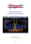
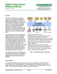
CoolRunner-II
[Guide
Title]
Common UG
Evaluation
Board
Template Set
Reference
Manual
[Guide Subtitle]
[optional]
UG000 (v1.0)
UG501
(v5.0) May
August
15, 24,
2008
2007 [optional]
R
R
Xilinx is disclosing this user guide, manual, release note, and/or specification (the "Documentation") to you solely for use in the development
of designs to operate with Xilinx hardware devices. You may not reproduce, distribute, republish, download, display, post, or transmit the
Documentation in any form or by any means including, but not limited to, electronic, mechanical, photocopying, recording, or otherwise,
without the prior written consent of Xilinx. Xilinx expressly disclaims any liability arising out of your use of the Documentation. Xilinx reserves
the right, at its sole discretion, to change the Documentation without notice at any time. Xilinx assumes no obligation to correct any errors
contained in the Documentation, or to advise you of any corrections or updates. Xilinx expressly disclaims any liability in connection with
technical support or assistance that may be provided to you in connection with the Information.
THE DOCUMENTATION IS DISCLOSED TO YOU “AS-IS” WITH NO WARRANTY OF ANY KIND. XILINX MAKES NO OTHER
WARRANTIES, WHETHER EXPRESS, IMPLIED, OR STATUTORY, REGARDING THE DOCUMENTATION, INCLUDING ANY
WARRANTIES OF MERCHANTABILITY, FITNESS FOR A PARTICULAR PURPOSE, OR NONINFRINGEMENT OF THIRD-PARTY
RIGHTS. IN NO EVENT WILL XILINX BE LIABLE FOR ANY CONSEQUENTIAL, INDIRECT, EXEMPLARY, SPECIAL, OR INCIDENTAL
DAMAGES, INCLUDING ANY LOSS OF DATA OR LOST PROFITS, ARISING FROM YOUR USE OF THE DOCUMENTATION.
© 2008 Xilinx, Inc. All rights reserved.
XILINX, the Xilinx logo, the Brand Window, and other designated brands included herein are trademarks of Xilinx, Inc. All other trademarks
are the property of their respective owners.
CoolRunner-II Evaluation Board
www.xilinx.com
May 15, 2008
Revision History
The following table shows the revision history for this document.
Date
Version
05/15/08
1.0
May 15, 2008
Revision
Initial Xilinx release.
www.xilinx.com
CoolRunner-II Evaluation Board
CoolRunner-II Evaluation Board
www.xilinx.com
May 15, 2008
R
CoolRunner-II Evaluation Board
Reference Manual
Overview
The CoolRunnerTM-II Evaulation Board is a complete USB-powered circuit
development platform for the Xilinx CoolRunner-II CPLD. The board includes
highly efficient power supplies, a user configurable oscillator, several user I/O
devices, a real-time current meter, and a USB port for board power and CPLD
programming. The board includes five expansion connectors that route 64 signals
available from the CPLD to external circuits to expand board capability.
Board features include:
•
A 256 macrocell CoolRunner-II CPLD in a TQ-144 package
•
An on-board USB port for board power, CPLD programming, and user data transfers
•
An on-board three-channel 16-bit Δ−Σ A/D converter that measures real-time current
on VCCINT and the two VCCIO banks during board operation (data is sent to the PC for
display via the USB cable)
•
A user-configurable silicon oscillator (1000/100/10 kHz), plus a socket for a second
crystal oscillator
•
64 I/O signals available on expansion connectors (32 on Pmod connectors; 32 on a
parallel connector)
•
Pads for an on-board SPI PROM
CoolRunner-II Evaluation Board
www.xilinx.com
1
R
Overview
Figure 1-1: CoolRunner-II Evaluation Board
Figure 1-2: CoolRunner-II Evaluation Board Block Diagram
2
www.xilinx.com
CoolRunner-II Evaluation Board
May 15, 2008
R
Software Installation
Software Installation
A Windows based CoolRunner-II Utility Window software application is provided with
the CoolRunner-II evaluation board. This application is used to program the CPLD, change
security settings, and monitor board current and temperature. This application should be
installed prior to connecting the board to a PC so that Windows will recognize the board
the first time it is plugged in. At this time, Windows XP and Vista (32-bit versions) are the
only supported operating systems for the Utility Window software.
Upon opening the package, you can easily test the board for basic functionality by
performing the following steps:
1.
Insert the Resource CD and click on ‘Software Install’ to install the CoolRunnerII Utility Window software.
2.
Attach the USB connector to a computer and the board. On the initial connection to the
USB port, the Add New Hardware Wizard will appear and ask you to install the driver.
When prompted, select to install the driver automatically. Once installed, the 3.3V
supply LED (LD5) on the CoolRunner-II board should light to show that the regulator
is enabled and the CPLD is powered.
3.
Start the CoolRunner-II Utility Window from :
Start → Programs → Digilent → Tools
4.
Press the Start button to begin viewing the power consumption for the device.
In order to program the CPLD, the ISE WebPACK software must also be installed.
1.
Insert the ISE WebPACK DVD and run the install program.
2.
Re-boot the PC.
3.
Ensure that the CoolRunner-II Evaluation Board is connected to the PC.
4.
Start the CoolRunner-II Utility Window program from:
Start → Programs → Digilent → Tools
5.
After the CoolRunner-II Utility Window appears, press the Browse button (shown in
Figure 1-3) and navigate to the desired JED file. (The demonstration JEDEC file is
present on the resource CD at /CR-II_board_files/demomain/top.jed).
Figure 1-3: Browse Button
CoolRunner-II Evaluation Board
May 15, 2008
www.xilinx.com
3
R
Demonstration Design
6.
Press the Program button to configure the CPLD (Erase will happen automatically
and does not need to be performed in advance of programming).
Demonstration Design
The design pre-programmed into the CPLD acts as the LCD module driver, as well as
implements a simple timer. The right-most two digits of the 7-segment display represent
time in seconds, the left-most two digits represent minutes. LED3 is a ‘heartbeat’ that
pulses every second. BTN0 is a push-button reset for the counter. BTN1 is a push-button
pause for the counter and LED display. SW0 is a slide switch for the DataGATE control
signal. The design is intended to operate with a clock frequency of 1 MHz (JP1 set to
bottom two pins). The design will still function with slower clock frequencies, but the
counter will operate slower and the 7-segment display will not refresh at a sufficient rate.
Without the LCD module installed, power the board and start the CoolRunner-II Utility
Window. Begin taking power measurements in the software. Notice how the power
changes when you change the position of clock frequency jumper (JP1). Naturally, the
faster clock results in increased power consumption. Now press and hold BTN0 (reset).
Notice a slight power reduction on VCCINT, as internal counters are held in reset. VCCIO is
relatively unchanged, as the input clock is still causing the input buffer to toggle. Next,
enable the DataGATE feature by sliding SW0 to the left. This blocks the clock signal from
the CPLD, so the design will halt operation. You will see power drop for VCCINT to
quiescent levels (in the 20 μA range). VCCIO also decreases as I/O power is saved by using
DataGATE. When you switch SW0 back to the right, note that the counter picks up where
it left off; you do not lose design data by entering this low power mode.
You should observe that the power change is gradual, and not instantaneous. This is a
result of the Average Filter option. This option is set to average out the curve displayed on
the screen. This is desired because the current is sampled roughly once a second, and the
power consumption of the device could be higher or lower than the average depending on
the active state of the design. For example, a circular shift register would have consistent
power measurements since the number of signals toggling every clock cycle is identical,
whereas a binary counter would not be consistent.
Now, plug the LCD module into ports J3 and J4. Press the reset button (BTN0) and the LCD
will initialize and scroll ‘Xilinx CoolRunner-II’ across the display.
Configuration
The CPLD on the CoolRunner-II Evaluation Board has been pre-programmed with the
project named ‘Demomain’. You can modify this design or create your own design from
schematics or HDL source files using the free ISE™ WebPack software from Xilinx.
Configuration files can be transferred to the CoolRunner-II Evaluation Board using a USB
cable and the CoolRunner-II Utility Window software, or using an external programming
cable (not provided) and Xilinx’s iMPACT software. If using the Xilinx programming cable
and iMPACT, attach the JTAG leads to the pins on J8. Once configured, the CPLD will
retain its state indefinitely.
When the CoolRunner-II Evaluation Board is powered on, the most recently loaded CPLD
configuration will be available immediately. A new configuration can be loaded at any
time, and as soon as a new configuration is loaded, it will define the CPLD’s behavior.
To configure the CPLD:
1.
4
Attach a USB cable to a host PC and to the CoolRunner-II Evaluation Board.
www.xilinx.com
CoolRunner-II Evaluation Board
May 15, 2008
R
Current and Temperature Meter
2.
Start the CoolRunner-II Utility Window software
Start → All Programs → Digilent → Tools → CoolRunner-II Utility Window
3.
Click the Browse button, select the desired .jed CPLD configuration file, and then
click on the Program button to configure the device.
To verify the image in the CPLD, click the Browse button, select the .jed CPLD
configuration file you want to verify, and click the Verify button.
To erase the CPLD, click the Erase button.
The Security button allows you to enable the Read Protect function of the CoolRunner-II
device. This selection will take effect the next time the CPLD is programmed. Read Protect
prevents the configuration file from being read back (therefore Verify operations will fail if
a device has Read Protect enabled). To clear the security, the current configuration file in
the CPLD must be erased.
Current and Temperature Meter
The CoolRunner-II Evaluation Board includes a three-channel A/D circuit that
continuously measures the current consumed by the CPLD core and both I/O banks, and
the also measures ambient temperature. Recorded data is sent to the PC where it
continuously updates a graph in the CoolRunner-II Utility Window. The current and
temperature meter is built around the Linear Technology LTC2494 16-bit delta-sigma
converter.
To use the current meter software, connect the CoolRunner-II Evaluation Board to the PC
and start the CoolRunner-II Utility Window software.
The current meter will acquire one temperature and nine current samples every two
seconds and transfer the samples to a data buffer on the PC via the USB cable. The
CoolRunner-II Utility Window software plots the data in a waveform graph, and shows
the most recent, maximum, minimum running average of the data obtained. To change the
scale of the plotted waveform, click the desired amperage/division radio button.
Temperature and current data will be recorded and displayed if the associated checkbox
for the data is checked. Un-checking a box will direct the software to ignore the associated
data channel.
An option checkbox for Average Filter is present to help smooth any dips or spikes, and to
provide an understanding of the average load on the power supply. Turning this off shows
‘real-time’ power consumption.
The Calibrate button is used to calibrate the temperature sensor to the proper value. This
only needs to be done once. The temperature reading can be viewed in Fahrenheit and
Celsius scales by selecting the appropriate radio button.
The Stop button causes the current meter to stop acquiring new data, and the Clear button
stops data acquisition, purges the data buffers, and clears the waveform display.
Use the Scale pull-down list box to view values on a different unit per division scale. Press
the Min, Avg or Max buttons respectively to view the minimum, average, or maximum
values for each measurement.
To save the data values in the buffer to a CSV (Comma Separated Value) file, click the Save
Buffer ... button and specify a file name (note the temperature and current values will only
be saved if their checkbox is checked). To load the data values from a CSV file into the
buffer, click the Load Buffer … button and specify a file name.
CoolRunner-II Evaluation Board
May 15, 2008
www.xilinx.com
5
R
Power Supplies
More detailed help on the software features can be found by clicking on ‘Help’ from the
CoolRunner-II Utility Window software.
Power Supplies
The CoolRunner-II Evaluation Board can be powered from its USB port, or from an
external supply attached at connector JP3 (jumper JP2 selects whether the board uses USB
power or external power). External power from any source is routed through a Linear
Technology LT3028 regulator to produce the two voltage supplies (3.3V I/O and 1.8V core)
required by the CPLD. Whenever board power is applied, the power-on LED will glow.
USB
Connector
Vin
Battery
Connector
JP2
JP3
LT3028
Regulator
3.3V
1.8V
USB
controller
Figure 1-4:
Enable
Regulator
To use an external power source, set jumper JP2 to “BAT” and apply power to the JP3 pins
(see board silkscreen for orientation). Any 3.6VDC to 9VDC power supply can be used (for
example, a transistor battery or 3 or 4 AA cells in series).
The CoolRunner-II Evaluation Board uses a four layer PCB, with the inner layers dedicated
to VCC and GND. The Linear Technology regulators, together with good power supply
routing and ample bypass capacitors on all IC pins result in a very clean, low-noise power
supply.
Clocks
The CoolRunner-II Evaluation Board includes a user-configurable silicon oscillator that
produces a 1 MHz, 100 kHz, or 10 kHz clock signal based on the position of the clock select
jumper at JP1. When the top two pins are jumpered, this produces a 10 kHz clock to the
CPLD. When no pins are jumpered, this produces a 100 kHz clock. The bottom two pins
jumpered produce a 1 MHz clock.
This primary oscillator output, labeled “PCLK” in the schematic, is connected to the
GCLK2 pin of the CPLD (at P38) so that it can be routed to the internal clock divider. A
socket for a standard half-size DIP oscillator is provided at location IC3.
Figure 1-5:
6
www.xilinx.com
Clock Circuits
CoolRunner-II Evaluation Board
May 15, 2008
R
User I/O
User I/O
The CoolRunner-II Evaluation Board provides two push buttons and two slide switches
for inputs, and four red LEDs and a four-digit LED display for outputs. The active-low
push buttons and slide switches include series resistance for short circuit protection.
The LEDs are active-low, and the seven-segment display uses transistors-decoupled
active-high common anode signals and active-low cathodes.
Figure 1-6: User I/O
Three additional status LEDs indicate USB power (LD4), board power (LD5), and USB data
activity (LD7). These signals are not driven by the CPLD, so are not shown in Figure 1-6.
Figure 1-7 shows the positioning of the segments in the display. Each segment is activelow. Since the four digits share the same data bus, the multiplexing of the data to the
display is done by the CoolRunner-II CPLD. If you wish to drive all digits with the same
CoolRunner-II Evaluation Board
May 15, 2008
www.xilinx.com
7
R
Expansion Connectors
value, simply drive AN1...4 low. If you wish to drive different values, you will need to
change the output on the Cx bus with the appropriate ANx signal. Since this transition can
happen at a high frequency, it gives the appearance that all digits are on simultaneously
when they are actually being turned on one at a time, but cycled rapidly.
Figure 1-7: Seven Segment Display
Expansion Connectors
The CoolRunner-II Evaluation Board provides four 12-pin peripheral module connectors.
Each connector provides two VCCIO and GND connections, and eight unique CPLD I/O
pins. Each connector can accommodate a single 12-pin Peripheral Module (Pmod) or two
6-pin Pmods.
Several 6-pin peripheral module boards that can attach to these connectors are available,
including speaker boards, H-bridge boards, sensor boards, etc. A convenient Peripheral
Module Bundle Kit is available at www.xilinx.com that contains eight popular peripheral
modules. Additional modules are available at www.digilentinc.com.
The CoolRunner-II Evaluation Board also provides a 40-pin expansion connector that
includes three power supply signals and 37 individual I/O signals. The following tables
provide pinout information for all expansion connectors.
8
www.xilinx.com
CoolRunner-II Evaluation Board
May 15, 2008
R
Expansion Connectors
The 12-pin peripheral module connections are shown in Table 1-1.
Table 1-1:
12-Pin Peripheral Module Connectors J1, J2, J3, and J4
Pin Number
J1 Pin
J2 Pin
J3 Pin
J4 Pin
1
CPLD I/O 10
CPLD I/O 142
CPLD I/O 119
CPLD I/O 104
2
CPLD I/O 7
CPLD I/O 139
CPLD I/O 117
CPLD I/O 102
3
CPLD I/O GTS 5
CPLD I/O 136
CPLD I/O 115
CPLD I/O 100
4
CPLD I/O GTS 3
CPLD I/O 134
CPLD I/O 113
CPLD I/O 97
5
GND
GND
GND
GND
6
3.3V
3.3V
3.3V
3.3V
7
CPLD I/O 9
CPLD I/O 140
CPLD I/O 118
CPLD I/O 103
8
CPLD I/O GTS 6
CPLD I/O 138
CPLD I/O 116
CPLD I/O 101
9
CPLD I/O 4
CPLD I/O 135
CPLD I/O 114
CPLD I/O 98
10
CPLD I/O GTS 2
CPLD I/O 133
CPLD I/O 112
CPLD I/O 96
11
GND
GND
GND
GND
12
3.3V
3.3V
3.3V
3.3V
The 40-pin expansion connector is shown in Table 1-2.
Table 1-2:
40-Pin J5 Connector
Expansion Pin Number
J5 Pin
1
GND
2
Voltage to regulator (5V if
USB powered)
3
3.3V
4
CPLD I/O 92
5
CPLD I/O 91
6
CPLD I/O 88
7
CPLD I/O 87
8
CPLD I/O 86
9
CPLD I/O 85
10
CPLD I/O 83
11
CPLD I/O 82
12
CPLD I/O 81
13
CPLD I/O 80
14
CPLD I/O 79
15
CPLD I/O 78
16
CPLD I/O 77
CoolRunner-II Evaluation Board
May 15, 2008
www.xilinx.com
9
R
LCD Peripheral Module (PmodCLP)
Table 1-2:
40-Pin J5 Connector (Cont’d)
Expansion Pin Number
J5 Pin
17
CPLD I/O 76
18
CPLD I/O 75
19
CPLD I/O 74
20
CPLD I/O 71
21
CPLD I/O 70
22
CPLD I/O 52
23
CPLD I/O 51
24
CPLD I/O 50
25
CPLD I/O 49
26
CPLD I/O 48
27
CPLD I/O 46
28
CPLD I/O 45
29
CPLD I/O 44
30
CPLD I/O 13
31
CPLD I/O 14
32
CPLD I/O 15
33
CPLD I/O 16
34
CPLD I/O 17
35
CPLD I/O 18
36
CPLD I/O 105
37
CPLD I/O 106
38
CPLD I/O 107
39
CPLD I/O 110
40
CPLD I/O 111
LCD Peripheral Module (PmodCLP)
The CoolRunner-II Starter Kit includes a 5 Volt 16x2 character LCD module called the
“PmodCLP”. This module is just one example of the many peripheral modules that are
available to quickly and easily extend the function of the evaluation board. Please see the
PmodCLP User Manual for more information.
Design Recommendations
10
•
The on-board regulator provides VCCIO of 3.3V, so set the default I/O standard
appropriately
•
Unused I/O termination should be set to ground to minimize power
www.xilinx.com
CoolRunner-II Evaluation Board
May 15, 2008
R
Taking the Next Step
•
Input termination should be set to keeper to minimize power consumption on any
potentially floating input pins
Taking the Next Step
If you are already familiar with Xilinx tools, you now have everything that you need to
perform design prototyping as well as evaluate coding styles with an eye on power
optimization. For users new to Xilinx ISE, we recommend the Programmable Logic
Handbook, included on the resource CD. The first few chapters provide a history on Xilinx
and programmable logic, and the later chapters provide step by-step instructions for
creating a design, synthesizing and implementing, and programming the CPLD.
Upcoming Features
New designs are being developed that will allow the user to transfer data into the CPLD
from a Windows interface, as well as utilize the microprocessor embedded in the Atmel
USB chip. Please visit the Digilent website (www.digilentinc.com) for the latest updates.
CoolRunner-II CPLDs support JEDEC readback as well as a signature setting, which are
not supported by the CoolRunner-II Utility Window at the time of initial release. These
features will be added in future versions of the software. If this functionality is needed, you
will need to purchase a programming cable and use the Xilinx iMPACT programming
software.
Troubleshooting
The first step with any software issue is to ensure that you have the most recent version of
the tools. Get the most recent service pack for ISE WebPACK here:
www.xilinx.com/support/download
Ther most recent version of CoolRunner-II Utility Window can be found here:
www.xilinx.com/cr2starter
Q: CoolRunner-II Utility Window does not recognize the device when I try to program, or
try to start capturing current/thermal data.
A:
♦
Re-connect both ends of the USB cable.
♦
Disconnect any leads attached to the JTAG header (J8)
♦
Verify that WebPACK is installed and the XILINX environment variable is set
properly.
-
The environment variable can be found by right-clicking
My Computer → Properties → Advanced tab → Environment Variables
-
Verify that the XILINX system variable has the correct installation location.
Q: CoolRunner-II Utility Window stops capturing data unexpectedly.
A: The software is dependant on receiving data at regular intervals. If you have many
processes running on your PC at the same time, it could be that the CR-II Utility
Window did not get its data in the expected sampling window, and then timed out. To
fix this, either increase the process priority for the CR-II Utility Window or run fewer
programs simultaneously while capturing data.
For Windows XP, increasing the process priority can be done via:
CoolRunner-II Evaluation Board
May 15, 2008
www.xilinx.com
11
R
Troubleshooting
♦
Press Ctrl-Alt-Delete
♦
Select Task Manager
♦
Select the Processes tab
♦
Find CoolRunnerIIUW and right-click on it
♦
Then set Priority to High
Q: Power consumption seems a little higher than I would expect. What can I do?
A:
♦
- Set the Unused IO Termination style to Ground, and Input Termination to
Keeper
♦
Ensure that you are not driving outputs on I/Os which are intended as inputs
(such as the buttons or slide switches)
♦
Ensure that the you have the proper I/O standard setting (3.3V)
Q: Why does the power reported by the CR-II Utility Window fluctuate?
A: The data sampled by the software is done roughly once every second. Since the
device is operating at a much faster rate, the point where the sample occurs could be at
a time coincident with design activity or not. A design that has much more predictable
activity, such as a circular shift register, will have much less fluctuations than a binary
counter.
Q: Where can I find updated documentation or software?
A: You can find the latest information for the CoolRunner-II Starter Kit here:
http://www.xilinx.com/cr2starter
For additional technical assistance, contact Xilinx support at :
http://www.xilinx.com/support/clearexpress/websupport.htm
To discuss design ideas with other users, see the Xilinx forums at :
http://forums.xilinx.com/
12
www.xilinx.com
CoolRunner-II Evaluation Board
May 15, 2008