1
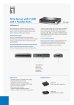
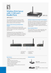
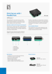
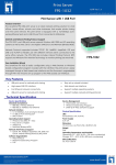
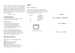
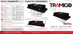
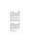
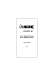
LevelOne
FSW-2106
5-Port 10/100 TX
+ 1-Port SC 100FX Switch
User Manual
Version 1.0-0604
1
2
1. Introduction
Thank you for purchasing LevelOne FSW-2106. The 5-port 10/100 TX +
1-port SC 100FX switch is a compact desktop size switch which is an ideal
solution for small office or SOHO network user. It provides wire-speed,
Fast Ethernet switching function that allows high-performance, low-cost
connection.
FSW-2106 provides 5 switched N-Way 10/100Mbps RJ-45 Ethernet ports
with Auto MDI/MDI-X function and one SC 100Base-FX fiber port. The
multi-mode fiber port can be used to connect to a remote side and
supports distance up to 2 KM.
The switch will automatically detect the speed of the device that you plug
into it to allow you to use both 10 and 100Mpbs devices. The 10Mbps
bandwidth
will
accommodate
simultaneously
providing
accommodate
multimedia
the
10Mbps
100Mbps
applications.
workgroup
bandwidth
The
switch
hubs
while
needed
to
features
a
store-and-forward switching and it can auto-learn and store source
address on a 2K-entry MAC address table.
Features
5 10/100Mbps N-Way ports
Supports Auto MDI/MDI-X function
One SC 100Mbps Fast Fiber port
Manual select full-duplex or half-duplex mode for fiber port
Store and forward switching architecture
Full wire speed forwarding rate
3
Package Content
One FSW-2106 switch
Four Rubber Feet with adhesive pads
Power adapter (9V DC, 700mA)
User Manual
FSW-2106
Rubber Feet
DC power Adapter
User’s Manual
Package Contents
Compare the contents of your FSW-2106 package with the standard
checklist above. If any item is missing or damaged, please contact your
local dealer for service.
4
2. Hardware Description
This section mainly describes the hardware of the FSW-2106 switch. This
switch is a compact palm size switch (6.5 inches) with 5x 10/100 N-Way
UTP ports plus one 100Baes-FX fiber port.
The physical dimensions of FSW-2106 are: 165mmx 100mmx 24mm
5
Front Panel
The LED indicators are located on the frond panel of the switch. They
provide a real-time indication of systematic operation status.
LED Indicators
The following table provides descriptions of the LED statuses and
meaning.
LED
Status
Color
Description
Power
On
Green
The power of switch is On
On
Green
The port is operating at the speed of
100Mbps.
100M
In 10Mbps mode or no device
Off
On
LINK /ACT
attached
The port is successfully connecting
Green
with the device.
The port is receiving or transmitting
Blinks
data.
Off
On
FDX/COL
No device attached.
The port is operating in Full-duplex
Yellow
mode.
Collision of Packets occurs in the
Blinks
port.
Half-duplex mode or no device
Off
attached.
6
Back Panel
The back panel of the switch consists of 5 10/100 N-Way UTP switch
ports, one 100Base-FX fiber port, 1 DIP-switch and DC power connector.
Back Panel of FSW-2106 switch
RJ-45 Ports: Five 10/100 N-Way auto-sensing for 10Base-T or
100Baes-TX connections.
100Base-FX Fiber Port: One SC 100Base-FX fiber port. The
distance for fiber cabling can be extended up to 2 kilometers.
DIP-switch: the DIP-switch is to select switch’s function.
UP: Fiber port operates on Full Duplex mode.
DIP 1
Down: Fiber port operates on Half Duplex
mode.
DC Power Connector: Plug DC Power Adapter’s female end into this
device, and the male end of DC Power Adapter into a power outlet.
The Adapter supply the switch with Voltage 9V, 700mA.
7
3. Network Application
This section provides you a few samples of network topology in which the
switch is used. In general, the switch is designed to be as a desktop or
segment switch.
The switch automatically learns node address, which are subsequently
used to filter and forward all traffic based on the destination address.
Desktop Application
The switch is designed to be a compact desktop size switch that is an
ideal solution for small workgroup. The switch can be used as a
standalone switch to which personal computers, server, printer server are
directed connect to form small workgroup.
Desktop Application
8
Collapsed Backbone Application
You can use any port of the switch to connect with another hub or switch
to interconnect each of your small-switched workgroups to form a larger
switched network. Meanwhile, you can also use fiber ports to connect
switches. The distance between two switches via fiber cable can be up to
2Kms.
The switch support Auto MDI/MDI-X function, the function can auto
detects the cable is straight or crossover cable. That is to say, you can
connect another hub or switch without crossover table.
Figure 3-2. Collapsed Backbone Application
In the above illustration, two switches are used to interconnect two small
workgroup via fiber cable. All the devices in this network can communicate
with each other. Connecting servers to the switch allow other users to
access the server’s data.
9
4. Troubleshooting
The switch can be easily monitored through panel indicators to assist in
identifying problems. This section describes common problems you may
encounter and where you can find possible solutions.
Diagnosing LED Indicator
If “LINK/ACT” indicator does not light up after connection, you may check
whether network interface (e.g., a network adapter card on the attached
device), network cable, or switch port is defective or not. Verify that the
switch and attached device are power on. Be sure the cable is plugged
into both the switch and corresponding device. Verified the proper cable
type is used and its length does not exceed specified limits.
Power
IF “Power” indicator does not light up when the power cord is plugged in,
you may have a problem with power outlet, or power cord. However, if the
switch powers off after running for a while, you should check for loose
power connections, power losses or surges at power outlet. IF you still
cannot resolve the problem, contact your local dealer for assistance.
Cabling
A、 RJ-45 ports:
Use unshielded twisted-pair (UTP) or shield
twisted-pair (STP) cable for RJ-45 connections: 100Ω Category3,4
or 5 cable for 10Mbps connections or 100Ω Category 5 cable for
100Mbps connections. Also be sure that the length of any twisted-pair
connection does not exceed 100 meters (328 feet).
B、 100Base-FX fiber port: Fiber multi-mode connector type must use
62.5/125 um multi-mode fiber cables. You can connect two devices
over a 2-kilometer distance.
10
5. Technical Specification
Standards
Compliance
IEEE 802.3 10Base-T Ethernet,
IEEE 802.3u 100Base-TX/FX Fast Ethernet
ANSI/IEEE 802.3 N-Way auto-negotiation
Protocol
CSMA/CD
Max Forwarding
Rate and
Max Filtering Rate
14,880 pps per Ethernet port,
148,800 pps per Fast Ethernet port
LED Indicators
RJ-45: 100M, LK/ACT, FD/COL (3 LEDs)
100M Fiber: 100M, LK/ACT, FD/COL (3 LEDs)
Per Unit: Power
Network Cables
10Base-T: 2-pair UTP Cat. 3, 4, 5 cable (100m),
EIA/TIA-568 100-ohm STP (100m)
100Base-TX: 2-pair UTP Cat. 5 cable (100m),
EIA/TIA-568 100-ohm STP (100m)
100Base-FX: 50, 62.5/125 micron multi-mode
fiber-optics 8,9/125 micron single-mode fiber-optics
Fiber Link Max.
Distance
SC Multi-mode: Full-duplex 2Km,
Half-duplex- 412m
Dimensions
165mm x 100mm x 24mm (L x W x H)
Operational
Temperature
0ºC to 45ºC (32ºF to 113ºF)
Operational
Humidity
10% to 90% (Non-condensing)
External Power
Supply
9 VDC, 700mA
Power
Consumption
5.5 Watt (maximum)
EMI
FCC Class A, CE Mark
11