1
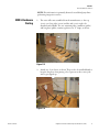
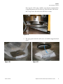
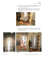
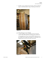
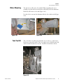
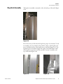
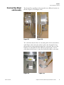
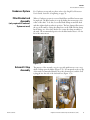
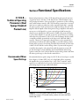
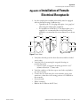
Integrator’s Reference Guide
Thermo Scientific HyClone
Single-Use Bioreactor
For use in biopharmaceutical applications
Integrator’s Reference Guide
Thermo Scientific HyClone
Single-Use Bioreactor (S.U.B.)
UG011 Rev 1
Preface
Patents and Trademarks:
The Thermo Scientific HyClone Single-Use Bioreactor is covered under US patents USPN 7,384,783
and 7,682,067 and 7,487,688. Other US and international patents are pending. KleenpakTM and Pall®
are registered trademarks of Pall Corporation. SmartSite® is a registered trademark of ALARIS Medical
Systems, Inc. C-Flex® and PharMed® are registered trademarks of Saint-Gobain. Envirotainer® is a
registered trademark of Envirotainer AB. Broadley-James® and BioNet® are trademarks of BroadleyJames Corporation. Applikon® is a trademark of Applikon Biotechnology. DeltaVTM is a registered
trademark of Emerson Process Management. TruViuTM is a registered trademark of Finesse Solutions, LLC.
CelliGen® and BioFlo® are registered trademarks of New Brunswick Scientific. BIOSTAT® is a registered
trademark of Sartorius BBI Systems. Terumo® is a registered trademark of Terumo Meical Corporation.
PharmPureTM is a registered trademark of PharmaPure Tubing. All other trademarks, registered
trademarks, or logos are properties of their respective owners.
NOTE: The drawings used throughout this document are representative only and may change. Please
refer to your Equipment Turn-Over Package (ETP) for your applicable drawings.▲
We have taken precautions to ensure this manual is accurate and complete. Nevertheless, readers should
remain alert to the possibility of errors and omissions. If any of the information in this manual seems
incorrect, contact Thermo Fisher Scientific for advice before proceeding. This information, including
product specifications, is subject to change without notice. Because of this, please take caution if
extracting information from this User’s Guide for use in other documentation as it will be updated with
future revisions. Please contact Thermo Scientific HyClone products technical support for the current
revision.
MANUAL NUMBER
1
REV
--
10/29/10
ECR/ECN
Date
Thermo Scientific
Integrator’s Reference Guide for S.U.B.
Description
ii
Table of Contents
Warnings and Safety...............................................................................1
Thermo Scientific
Section 1
Initial Installation Instructions...............................................................3
Section 2
Functional Specifications.....................................................................28
Section 3
Product Information..............................................................................34
Section 4
Troubleshooting....................................................................................35
Section 5
Ordering Information.............................................................................41
Appendix A
Electrical Receptacle Installation Instructions....................................50
Appendix B
Calibration of the AC-Tech Variable Speed Drive.................................52
Appendix C
Mettler Toledo Load Cell Calibration Instructions................................53
iii
Warnings and Safety
Warning: Read and understand operator’s manual before using this
equipment.
Thermo Scientific HyClone Single-Use Bioreactor is designed to be
operated under traditional mammalian cell culture conditions. A general
understanding of bioreactor systems and their operation is important prior
to using the system for the first time. ▲
•• Read and understand user’s manual before operating
•• Failure to do so could result in injury
Warning: Hazardous voltage inside
Disconnect power before opening. Service by trained personnel only.
Consult manual. Electrical components are designed into and required
for the proper function of the Single-Use Bioreactor (S.U.B.) The mixer
motor, motor controller, resistive heater jacket and control panel all have
electrical components. ▲
•• Risk of electrical shock and injury
•• There is potential for static charge build-up during mixing and set-up
of BPCs
Warning: Entanglement hazard
Rotating parts can cause injury. Keep hands away from moving parts. ▲
Warning: Hot surface. Do not touch.
The heating jacket is designed to heat the outer vessel wall. Normal
operating conditions generate heat and could create hot surfaces. ▲
•• Hot surface inside
•• Contact with surfaces may cause burns
•• Do not touch while in operation
Warning: Burst Hazard
Under normal operating conditions the S.U.B. BPC chamber is under
slight pressure. Normal passive venting prevents any excess of pressure
building up within the chamber. Chamber pressure and inlet line pressure
should be monitored for proper settings. ▲
•• Contents under pressure
•• Do not exceed 0.5 psi (0.03 bar) BPC pressure
•• Do not exceed 5 psi (0.34 bar) inlet pressure
•• Assure vent filter is properly positioned and working properly
Thermo Scientific
Integrator’s Reference Guide Single-Use Bioreactor (S.U.B.)
1
Warnings and Safety
Protective Earthing
Environmental
Conditions
Water Jacket
Vessel Information
Protective earthing must be verified prior to plugging the S.U.B. into any
electrical outlet. Ensure the receptacle is properly earth grounded.
••
••
••
••
Operating: 17°C to 27°C; 20% to 80% relative humidity, noncondensing
Storage: -25°C to 65°C
Installation category II (over voltage) in accordance with IEC 664
Altitude Limit: 2,000 meters
The Water Jacket S.U.B. has been designed to be operated with water as
the heat transfer medium with temperatures not exceeding 60°C (140°F)
under less than 150 psi (1 MPa) operating pressure.
NOTE: The S.U.B. BPC operating limits for temperature are 5 to 40°C
and an internal pressure of less than 0.5 psi. The water jacket is not
classified as a pressure vessel and is not required to be registered, inspected
and stamped with the Code U symbol per section U-1(c)2(f ) of the
ASME Boiler and Pressure Vessel Code [operating with water as the heat
transfer medium, temperature not exceeding 99°C (210°F) under less
than 300 psi (2 MPa)]. In Europe, to conform to the Pressure Equipment
Directive 97/23/EC (PED), all S.U.B. jacketed systems should be
operated at 75 psi or less. However, if operating conditions require usage
outside of the above recommended parameters, a stamped jacket can be
obtained for an additional fee.
Thermo Scientific
Integrator’s Reference Guide Single-Use Bioreactor (S.U.B.)
2
Section 1
Initial Installation Instructions
Section 1 Initial Installation
Instructions
Hardware Shipment
and Setup
The Single-Use Bioreactor hardware is shipped directly from the
manufacturer and will arrive crated. For unpacking instructions and
detailed contents of the crate, please refer to the instructions specific to the
S.U.B. volume. Be sure to follow the unpacking instructions provided and
retain all packaging materials.
50 L, 100 L, 250 L and
500 L Hardware
Uncrating
The S.U.B. hardware should arrive with the following items:
•• Outer support container (platform, tank and control panel)
•• Drive shaft, RTD, probe shelf and brackets (4) and standard tool set
(spanner wrench and torque wrench)
•• ETP - located on CD provided with hardware
1.
2.
3.
4.
5.
Remove crate lid first
Remove side wall(s)
Remove the tie-down straps
Remove any/all blocks on crate floor
Remove S.U.B. carefully using forklift/manually by lifting via the
bottom of the cart frame, not the casters
6. Ensure no damage occurred during shipping
Contact your Sales Representative immediately if damage has occurred.
Thermo Scientific
Integrator’s Reference Guide Single-Use Bioreactor (S.U.B.)
3
Section 1
Initial Installation Instructions
1000 L Hardware
Uncrating
The S.U.B. hardware should arrive with the following items:
•• Outer support container (platform, tank and control panel) - main
shipping container
•• Motor (boxed) - located inside tank
•• Drive shaft, RTD, pressure transducer cable, probe shelf and brackets
(5), and standard tool set (4 pieces) - items are located in the foam
packaging within the tank (Figure 1.6)
•• ETP - located on CD provided with hardware.
Drive shaft (3 or 4 segments)
RTD
Open-end wrench
Spanner wrench
Motor with mounting bracket
(packaged separately for jacketed version)
Torque wrench
Probe shelf
Open-end wrench
Pressure transducer cable
Exhaust filter holder
(packaged separately for jacketed version)
Probe fingers (5)
Figure 1.6. Foam packaging configuration for 1000 L S.U.B.
Thermo Scientific
Integrator’s Reference Guide Single-Use Bioreactor (S.U.B.)
4
Section 1
Initial Installation Instructions
Motor Mounting
(1000 L)
Please reference the following instructions to mount the S.U.B. motor for
first time setup or if the unit is to be transported. NOTE: Ensure S.U.B. is
in final location as overall height with motor mounted is greater than 82”
and may not fit through standard door frames. Mounting of the motor
requires two persons; please exercise caution when working in elevated
positions. References to figures are shown in parentheses following each
step.
1. Remove the protective shipping bracket above the control panel (four
3/8” bolts) and store in original crate. Keep the 3/8” bolts for use in
mounting the motor to the tank.
2. Attach the motor with mounting plate to the outside of the tank
above the load cell summing block and control panel (Figure 1.7
or 1.8) using four (qty 4) 3/8”-16 x 1” fasteners from step 1 above.
NOTE: The bottom two bolts are also used to mount the tool
bracket on the Water Jacket 1000 L S.U.B. as shown in Figure 1.8.
3. Attach the motor lead to the control panel quick connect (Figure 1.9
or 1.10).
Figure 1.7. Electric Resistive Heater
Figure 1.8. Water Jacket
Still waiting for image from Nephi
Figure 1.9. Electric Resistive Heater
Thermo Scientific
Figure 1.10. Water Jacket
Integrator’s Reference Guide Single-Use Bioreactor (S.U.B.)
5
Section 1
Initial Installation Instructions
Additional Items for
Installation
(1000 L)
1. Resistive Heated S.U.B.: Attach the exhaust filter bracket (fingers
facing toward tank center) to the top strap of the tank (if looking at
the control panel, use the strap on the left side) using the two 1/4 20 x 1/2” button head fasteners (use 5/32” hex wrench) located on
the strap (Figure 1.11). Exact position of the bracket can be adjusted
once the BPC is loaded. For elevated vent filters, mount the adapter
piece and the extended filter bracket (Figure 1.14).
2. Jacketed S.U.B.: Mount bracket base first; loosen the three button
head fasteners allow 1/4” of space between head and plate. Align the
fasteners to the key-hole cut outs in the tank and slide to bottom.
Tighten fasteners to lock the plate in position (Figure 1.12). The
swivel arm of the upper bracket can then be placed into the lower
receiver. Final position of the bracket can be adjusted once the BPC
is loaded (Figure 1.13). Alternatively, an extended height dual filter
bracket can be installed for elevated vent filters (Figure 1.14)..
.
.
.
.
.
.
.
.
.
.
.
.
Figure 1.12. Water Jacket (mounting
Figure
1.11.
Electric
Resistive
Heater
.
base assembly)
(mounting
standard
vent
holder)
.
.
.
.
.
.
.
.
.
.
.
.
.
.
.
Figure 1.13. Water Jacket
(mounting standard vent holder)
Thermo Scientific
Figure 1.14. Extended Dual Vent
Filter Bracket in use
Integrator’s Reference Guide Single-Use Bioreactor (S.U.B.)
6
Section 1
Initial Installation Instructions
3. Attach the probe shelf across the lower probe access cutout by
inserting the two tabs into the slots (Figure 1.15 and 1.17) and hand
tightening the knobs (Figure 1.16 and 1.18).
Thermo Scientific
Figure 1.15. Electric Resistive Heater
Figure 1.16. Electric Resistive Heater
Figure 1.17. Water Jacket
Figure 1.18. Water Jacket
Integrator’s Reference Guide Single-Use Bioreactor (S.U.B.)
7
Section 1
Initial Installation Instructions
2000 L Hardware
Uncrating
1. Remove top cover.
Figure 1.18
2. Remove small side cover.
Figure 1.19
3. Remove both long side covers.
Figure 1.20
Thermo Scientific
Integrator’s Reference Guide Single-Use Bioreactor (S.U.B.)
8
Section 1
Initial Installation Instructions
4. While in the horizontal position, remove both boxes (miscellaneous
tools kit & motor assembly) and the packaging material. If this step
is missed, both boxes can be removed through the large access door
when the tank it is vertical.
Figure 1.21
Figure 1.22
Figure 1.23
Figure 1.24
Thermo Scientific
Integrator’s Reference Guide Single-Use Bioreactor (S.U.B.)
9
Section 1
Initial Installation Instructions
5. Using either a fork lift or overhead crane, the unit needs to be
tipped from horizontal to vertical. Ensure all straps are secure before
proceeding. Below are descriptions of both the forklift and overhead
crane methods.
Forklift Method
(Preferred)
The next step is to lift the crate up. You will need about 10 feet of ceiling
height above the crate. Lift the crate to vertical using the two eye bolts
on the crate end with a 1” nylon, 2 leg sling with sling hooks, part #
8864T821 Mcmaster-Carr or equivalent. Also use a 2” wide by 2’ long
web sling (3360T571) and a web sling shackle with screw pin (35505T3).
Part Number
Description
Vendor
8864T821
1” nylon double leg sling with hooks
McMaster-Carr
3360T571
2” wide x 2’ long web sling
McMaster-Carr
35505T3
Shackle for 2” web
McMaster-Carr
Table 1.4. Recommended Lift Kit
Remove forks from forklift to keep them from damaging tank. Using
eyebolts on crate, attach slings to forklift. While lifting the crate, the
forklift will need to move forward at the same time to avoid the bottom of
the crate sliding back.
Figure 1.25
Thermo Scientific
Integrator’s Reference Guide Single-Use Bioreactor (S.U.B.)
10
Section 1
Initial Installation Instructions
Overhead Crane
Method
In most cases, the overhead crane is free floating on the I-beam to which
they are mounted, so for this method to work, two lifts need to be used.
Use the same kit, as defined in table 1, and choke strap. This choke strap
needs to be wrapped around the bottom base, as shown, and hooked up
to the second lift, as in the picture below. Both lifts are raised to get the
crate off the floor, but the eye bolt side will be raised higher, as shown. The
strap side will then be lowered simultaneously as the eyebolt side is raised,
until the crate is vertical.
Figure 1.26
Uncrating Continued
6. Remove straps from around the tank. Be careful with the bag lift
(hoist) while doing this to make sure it doesn’t fall. Remove the bag
lift during this same step.
Figure 1.27
Thermo Scientific
Integrator’s Reference Guide Single-Use Bioreactor (S.U.B.)
11
Section 1
Initial Installation Instructions
7. Remove bag lift arms from bottom of crate.
8. Remove lag bolts from the feet of the S.U.B. unit.
Figure 1.28
9. Lift the tank out of the crate, using either a fork lift or an overhead
crane.
10. Remove all packaging materials and prepare for assembly.
Figure 1.29
Thermo Scientific
Figure 1.30
Integrator’s Reference Guide Single-Use Bioreactor (S.U.B.)
12
Section 1
Initial Installation Instructions
NOTE: This information is primarily directed toward third party firms
performing integration services.
2000 L Hardware
Crating
1. The crate will come assembled from the manufacturer, so the top
(cover), two long sides (covers) and the end (cover) need to be
detached and available. The two remaining sides, small base (pallet)
and long base (pallet), remain together in an “L” shape, as shown.
Figure 1.31
2. Attach two 8’ tie downs, as shown. They need to be installed firmly to
keep the long base from putting a lot of pressure at the corner joint
after it gets tipped up.
Figure 1.32
Thermo Scientific
Integrator’s Reference Guide Single-Use Bioreactor (S.U.B.)
13
Section 1
Initial Installation Instructions
3. The next step is to lift the crate up. You will need about 10 feet of
ceiling height above the crate. Lift the crate to vertical using the two
eye bolts on the end with a 1” nylon, 2 leg sling with sling hooks,
part # 8864T821 Mcmaster-Carr or equivalent. Also use a 2” wide by
2’ long web sling (3360T571) and a web sling shackle with screw pin
(35505T3). Remove forks for convenience and to avoid damaging
the crate. Refer to Table 1.4 for the recommended lift kit.
Figure 1.33
4. The 2000 L S.U.B. can be moved in two different ways: 1) a fork lift
at the base, and 2) using the two eye bolts located at the top of the
S.U.B. itself. .
Figure 1.34
Thermo Scientific
Integrator’s Reference Guide Single-Use Bioreactor (S.U.B.)
14
Section 1
Initial Installation Instructions
If moving the S.U.B. using a forklift, ensure that the summing block
is tipped up and moved out of the way of the fork tines. Also ensure
that a strap secures the tank to the fork lift for security.
Figure 1.35
5. The sparge plate inside the tank needs to be bubble wrapped and tied
down.
Figure 1.36
Thermo Scientific
Figure 1.37
Integrator’s Reference Guide Single-Use Bioreactor (S.U.B.)
15
Section 1
Initial Installation Instructions
6. The tank needs to be wrapped completely with bubble wrap, followed
by stretch wrap. Fittings up to the tee of the jacket need to be
removed (as shown in Figure 1.38)
7. We recommend positioning the tank using a fork lift underneath
the base, but the option of using the tank eye bolts is available for
overhead cranes. Figure 1.38
8. Orient tank as shown. If necessary, locating boards can be removed
and positioned to fit the feet. Also, straps may need to be loosened to
let the tank pass through.
Figure 1.39
Thermo Scientific
Figure 1.40
Figure 1.41
Integrator’s Reference Guide Single-Use Bioreactor (S.U.B.)
16
Section 1
Initial Installation Instructions
9. Install 12’ straps around the tank, using the eyebolts provided. Use
strips of foam underneath the straps to further protect the tank.
Figure 1.42
10. Ensure all straps are secure and tight.
11. To tip the tank down using a fork lift, the forks must first be
removed. This will keep them from damaging the tank. We also
recommend the same set up as mentioned before lifting the crate
up vertically. The fork lift needs to pull the crate back and lower it
simultaneously to lay the crate/S.U.B. system down.
Figure 1.43
Thermo Scientific
Integrator’s Reference Guide Single-Use Bioreactor (S.U.B.)
17
Section 1
Initial Installation Instructions
Thermo Scientific
Figure 1.44
Figure 1.45
Figure 1.46
Figure 1.47
Integrator’s Reference Guide Single-Use Bioreactor (S.U.B.)
18
Section 1
Initial Installation Instructions
12. With the tank secured in a horizontal position, each foot needs to
have one lag screw, 3/8” x 4”, installed to keep the base from putting
a side load on the load cells during shipment. Ensure the lag screws
go into the 4x4 underneath the feet.
Figure 1.48
Figure 1.49
Figure 1.50
Figure 1.51
13. Bag Lift: Remove the spider arm from the bag lift. Bubble wrap both
pieces and finish with stretch wrap (Figure 1.51).
Thermo Scientific
Integrator’s Reference Guide Single-Use Bioreactor (S.U.B.)
19
Section 1
Initial Installation Instructions
14. Attach bag lift frame to bottom of the small base using a cloth strap
(1585T22) and steel wire buckles (1958T85). You will need to staple
the cloth straps to the plywood base and tension them with the wire
buckles.
15. Remove straps and place bag lift assembly next to tank and resting on
the cradles with the small arm in vertical position. Ensure the control
box on the beam leaves enough clearance for the side of the crate to
be installed. Once in place, strap the bag lift down using the same
cloth strapping, staples and ring buckles.
Figure 1.52
Figure 1.53
Figure 1.54
Thermo Scientific
Integrator’s Reference Guide Single-Use Bioreactor (S.U.B.)
20
Section 1
Initial Installation Instructions
16. Re-install tank straps, but add dense card board and/or thick foam
between the buckle and the tank.
17. Lay ½” dense foam along bottom inside of tank for kneeling and
access to the end of the tank to prevent damaging stainless finish. Insert miscellaneous parts box first, followed by the motor assembly
box. Tip them upright, as shown, and run ratchet strap from eyebolt
to eyebolt going through the bottom sensor port access to the
hanging tab access holes. Place high density cardboard and thick
foam in between strap and all sharp corners before tensioning strap.
Figure 1.55
Figure 1.56
Figure 1.57
Figure 1.58
18. Double check all straps are properly tensioned and all points where
straps cross sharp corners are properly padded.
19. Install both long sides
20. Install end cover.
21. Install top cover.
22. Paint and/or mark on all sides to “Open top cover first and read
instructions before proceeding to unpack crate.” Thermo Scientific
Integrator’s Reference Guide Single-Use Bioreactor (S.U.B.)
21
Section 1
Initial Installation Instructions
2000 L S.U.B.
Assembly
Instructions
Tank Bottom
The tank bottom has two main access cut-out plates, one for the open
pipe sparge and the bottom drain (harvest) ports and the other for three
porous frit sparge ports (Figure 1.59).
(3) Porous frit sparge ports
Open pipe and bottom
drain ports
Figure 1.59
Place the white plastic (Delrin) circular plate with two slots in the center
recessed hole (Figure 1.59). The frit sparge tube port access rectangular
plate is shown at the top of the Figure 1.59. This access plate is secured
on one corner to let it rotate out of the way during installation of the
disposable S.U.B. The stud may be tightened down for shipping to keep
the plate from bouncing. To do this, unscrew the nylock nut underneath
the plate about an inch (Figure 1.60). This will give the mechanism
enough space to lift and rotate out of the way.
Figure 1.60
Thermo Scientific
Integrator’s Reference Guide Single-Use Bioreactor (S.U.B.)
22
Section 1
Initial Installation Instructions
Motor Mounting
The tank motor will need to be installed. When unpacking the motor
assembly, note that the bolts and washers will already be in the aluminum
block that will mount to the tank (Figure 1.61).
Use these bolts to mount the aluminum block to the stainless tank (Figure
1.62). Figure 1.61
Tank Tool Kit
Figure 1.62
The tool holder is installed just behind the motor with two socket button
head screws, nuts and washers. There is enough room to hold the nuts and
washers inside the tank motor mount. Install tools and shaft as shown.
Figure 1.63
Thermo Scientific
Integrator’s Reference Guide Single-Use Bioreactor (S.U.B.)
23
Section 1
Initial Installation Instructions
Bag Hoist Assembly
The bag hoist assembly is mounted on the side and top of the tank (Figure
1.64). Figure 1.64
First remove the eye bolt where the bag lift is going to be mounted. To aid
in assembly, a slot is provided on the tank for a finger of the bag lift to fit
into to hold the bottom of the bag lift next to the tank (Figure 1.65). The
bag lift also has a hook that engages the top lip of the tank (Figure 1.66).
Once bag lift is in position, use the eye-bolt to mount it securely to the
top of the tank (Figure 1.66).
Figure 1.65
Thermo Scientific
Figure 1.66
Integrator’s Reference Guide Single-Use Bioreactor (S.U.B.)
24
Section 1
Initial Installation Instructions
Electrical Box Mount
and Assembly
The electrical box assembly can be mounted in two different locations on
the base (Figure 1.67 and Figure 1.68).
Figure 1.67
Figure 1.68
Two of the three base feet have two mounting holes for the electrical box
stand (Figure 1.69). Once the stand is in place, the electrical box has a
plate mounted on the back that matches up to the stand. The top of the
stand has two threaded holes that will line up with the plate. Use two
socket button head screws to secure the electrical box plate to the stand.
Figure 1.69
Thermo Scientific
Figure 1.70
Integrator’s Reference Guide Single-Use Bioreactor (S.U.B.)
25
Section 1
Initial Installation Instructions
Condenser System
For Condenser set up and use, please refer to the Single-Use Bioreactor
User’s Guide, Section 2.4, beginning on page 78.
Filter Bracket and
Assembly
When a Condenser system is not used, dual filters and filter heaters must
be employed. The filter bracket is set up by sliding the mounts up to the
collar on the shaft. To do this, loosen the black clamps around the shaft
and then tighten back up when in position. The base clamp will mount to
the top of the tank by setting the clamp base on the SUB with the clamp
knobs facing out. Screw these knobs in to secure the clamp assembly to
the tank. The recommended position for the filter bracket base is 1-2 feet
left of the mixer motor.
(only required if Condenser
System not used)
Figure 1.71
External E-Stop
Assembly
The purpose of the external e-stop is to provide quick access to an e-stop
while working upon the ladder (Figure 1.72). It is mounted on the top lip
of the tank (recommended directly above the electrical box) and the cord
is plugged into the side of the electrical box (Figure 1.73).
Figure 1.72
Thermo Scientific
Figure 1.73
Integrator’s Reference Guide Single-Use Bioreactor (S.U.B.)
26
Section 1
Initial Installation Instructions
Harsh Mount Display
A harsh mount display can be mounted on top of the electrical box stand
(Figure 1.74). The two mounting holes on top match the bolt pattern of
the Harsh Mount Display (Figure 1.75).
Figure 1.74
Thermo Scientific
Figure 1.75
Integrator’s Reference Guide Single-Use Bioreactor (S.U.B.)
27
Section 2
Functional Specifications
Section 2 Functional Specifications
2.1 S.U.B. –
Technical Operating
Parameters (Dual
Sparge Standard
Product Line)
Recommended Mixer
Speed Settings
Functional performance of the S.U.B. depends largely upon the amount
of agitation used to mix the S.U.B. and can have a direct influence upon
cell growth performance of the system (due to parameters of shear, mixing
time, and heat/mass transfer). All S.U.B. hardware systems have oversized
mixer motors with gear reductions and a removable rigid shaft – typically
the mixer speed for each system must be scaled based upon the size of the
impeller and the liquid volume being mixed. Larger impellers will transfer
more power to the liquid for a given rotational speed and because the
design uses an angled mixer shaft instead of baffles, all systems will begin
to vortex if the impeller is operated at excessive speed. Excessive vortexing
will reduce the performance of the S.U.B. and can damage the drive shaft
or impeller assembly (particularly in the larger scale 1000 and 2000 L
systems). Therefore it is imperative that the mixer not be operated above
nominal speed without the tank being filled to near full working volume.
During drain operation, the mixing should be discontinued once the tank
volume is below half the rated working volume. Systems with integrated
controllers that employ safety interlocks with the agitation system will
provide the highest system reliability; this should include deactivating
agitation when the vessel is below half the rated working volume and limit
the mixer speed ranges as listed in the matrix below.
Recommended mixer speed settings for all S.U.B.s are based upon a scaled
Power Input to Volume (PIV) ratio of 0.1 hp/1000 gallons (assuming
the impeller has a power number, Np = 2.01). These “nominal” mixer
speeds are recommended as the process development starting point for
performing suspension type animal cell culture.
0.300
2000 L
1000 L
0.250
PIV (hp/1000gal)
500 L
0.200
250 L
100 L
0.150
50 L
0.100
0.050
0.000
0
50
100
150
200
250
Rotation speed (RPM)
Graph 2.1 S.U.B. Mixing Power Input to Volume Estimations: (Simulation
assumes the system is fill to rated working volume with water and Power
Number (Np) =2.07)
Thermo Scientific
Integrator’s Reference Guide Single-Use Bioreactor (S.U.B.)
28
Section 2
Functional Specifications
Standard Range Mixer
Speed
Standard range mixer speed for all S.U.B.s is listed in Table 2.1. The mixer
of the S.U.B. can be operated within this range of agitation speeds with
fluid volumes anywhere from 50 to 110% of the rated working volume. In
general, it is recommended as good practice to reduce the mixer speed of
the impeller as the batch volume decreases in order to avoid excess shear
and vortexing. The high end of this range represents 0.2 hp/1000 gallons
in the 50-1000 L systems and 0.1 hp/1000 gallons in the 2000 L.
Extended Range Mixer
Speed
Extended range mixer speeds are the maximum recommended speeds for
use with the S.U.B. but are to be used only under controlled conditions
(meeting the following criteria). An interlock between the bioreactor
controller and the reactor vessel is required to ensure reliable operation –
in this case the standard range of mixer speeds cannot be exceeded unless
the vessel is at 90% of working volume or greater. Load cells or a means
to monitor batch volume should be the parameter interlock defined as
90-110% of the rated working volume. The upper end of this range
represents 0.25 hp/1000 gallons in the 50-1000 L S.U.B. and .
0.2 hp/1000 gallons in the 2000 L S.U.B.
S.U.B.
Size
50 L
100 L
250 L
500 L
1000 L
2000 L
Nominal Setting
(100% Working Volume)
Recommended
Mixer Speed
169 rpm
146 rpm
118 rpm
100 rpm
87 rpm
75 rpm
Standard Range
(50-110% Working Volume)
VFD Settings
Mixer Speed
(P24 and P39)
30-213 rpm
72 Hz
30-183 rpm
61.7 Hz
30-150 rpm
63.2 Hz
30-128 rpm
21.6 Hz
20-110 rpm
55.6 Hz
20-75 rpm
37.8 Hz
Extended Range
(90-110% Working Volume Only)
VFD Settings
Mixer Speed
(P24 and P39)
20-230 rpm
77.5 Hz
20-197 rpm
66.4 Hz
20-161 rpm
67.9 Hz
20-138 rpm
23.3 Hz
20-118 rpm
60.4 Hz
20-95 rpm
47.9 Hz
Table 2.1 Agitation and Specification Matrix (NOTE: The recommended VFD settings will
scale the analog output of the VFD according to mixer speed listed (typically 0-10 VDC).
Recommended Batch
Temperature Setting
Recommended batch temperature setting is specified for growing most
animal culture cultures, typically 37°C. However, specific applications
will vary and the set point can be adjusted within the standard batch
temperature range. Batch (process) temperature calibration should be
verified on-site to ensure accuracy. See S.U.B. Facility Requirements Table
for more information on the TCU specifications for water jacketed systems.
S.U.B.
Size
50 L
100 L
250 L
500 L
1000 L
2000 L
Recommended Batch
Volume Range
25-55 L
50-110 L
125-275 L
250-550 L
500-1100 L
1000-2200 L
Recommended Batch
Temperature Setting (100% WV)
37°C
37°C
37°C
37°C
37°C
37°C
Standard Batch
Temperature Range
5-40°C
5-40°C
5-40°C
5-40°C
5-40°C
5-40°C
Table 2.2 Temperature Specification Matrix
Thermo Scientific
Integrator’s Reference Guide Single-Use Bioreactor (S.U.B.)
29
Section 2
Functional Specifications
Standard Batch
Temperature Range
Sparging, Off-gassing,
and Backpressure
Specification
S.U.B.
Size
50 L
100 L
250 L
500 L
1000 L
2000 L
Micro Sparge Flow
Rate Setting
(at 100% working volume)
Suggested
Rated
Maximum Maximum
0.5 lpm
25 lpm
1 lpm
25 lpm
2 lpm
25 lpm
4 lpm
55 lpm
8 lpm
55 lpm
16 lpm
70 lpm
Standard batch temperature range defines the temperature settings
that are acceptable for use with the single use S.U.B. BPC (see Table
2..2). Resistive heated hardware cannot be actively cooled below
room temperature; the jacketed systems can be operated down to
batch temperatures of 5°C. The maximum recommended upper
batch temperature for either system type is 40°C. Elevating the batch
temperature beyond 40°C is not recommended as this reduces system
reliability or may irreparably damage the S.U.B. BPC.
Proper gas management in the S.U.B. should be a conservative balance
between providing good mass transfer while managing bubble shear force,
foaming, and internal BPC back pressure. Flow rates approaching or
exceeding the suggested maximum values will likely necessitate the use of
antifoam additives in the media.
Macro Sparge
Flow Rates
(at 100% working volume)
Suggested
Rated
Maximum Maximum
2 lpm
25 lpm
4 lpm
25 lpm
6 lpm
25 lpm
8 lpm
65 lpm
10 lpm
65 lpm
12 lpm
65 lpm
Overlay Sparge
Flow Rates
Off-Gassing Flow Rates
SUB-BPC Internal
Pressure – Not to Exceed
Suggested
Maximum
5 lpm
5 lpm
5 lpm
10 lpm
10 lpm
Rated
Maximum
25 lpm
25 lpm
25 lpm
25 lpm
50 lpm
Suggested
Maximum
10 lpm
10 lpm
10 lpm
25 lpm
25 lpm
Rated
Maximum
25 lpm
25 lpm
25 lpm
50 lpm
50 lpm
Suggested
Maximum
<0.1 psi
<0.1 psi
<0.1 psi
<0.1 psi
<0.1 psi
Rated
Maximum
0.5 psi
0.5 psi
0.5 psi
0.5 psi
0.5 psi
50 lpm
100 lpm
50 lpm
100 lpm
<0.1 psi
0.5 psi
Table 2.3 Sparging, Off-gassing, and Backpressure Specification Matrix
Micro Sparge Setting
The suggested setting is based upon experience of providing good oxygen
transfer without excessive shear, coalescing, or foam generation.
Macro Sparge Setting
The suggested setting is based upon experience of providing good oxygen
transfer with the benefit of providing CO2 stripping and some improved
control against foam generation.
Overlay Sparge Setting
The amount of overlay allowed is best set by determining the balance of
gas exhaust vent flow capacity still available, while keeping the internal
back pressure of the S.U.B. BPC under safe operating conditions. Typical
applications with the S.U.B. will not require the use of the overlay vent if
the open pipe spare is being used.
Thermo Scientific
Integrator’s Reference Guide Single-Use Bioreactor (S.U.B.)
30
Section 2
Functional Specifications
Maximum Flow Ratings
Operating Pressure
Sparge Flow Meter
Recommendations
S.U.B.
Size
Maximum flow ratings are based upon the physical and mechanical
limitations of each sparger flow channel of the standard BPC assembly
(flow restrictions related to filters, check valves, diffusers not to exceed a
pressure drop of 10-psi). In practice it is expected that most users will not
operate near these maximum ratings.
Operating Pressure must be considered as part of developing a robust
cell culture process and it is good practice to avoid conditions that will
make the top of the S.U.B. BPC bag appear tight (>0.1 psi). Typically
the exhaust vent filters will block over time, thus reduced capacity will
increase pressure drop across the filter media as the run progresses. Vent
filter heaters are recommended in order to flash condensate that may
accumulate near or on the filter media. Maximum rated operating pressure
is 0.5 psi; exceeding this increases drive shaft wear and may result in
bursting the BPC (typically at a location above liquid level). Applications
requiring large gas flow can use the Single-Use Bioreactor Condenser
System to provide additional protection and reliability.
Flow meters should be scaled for the proper vessel size depending upon
the maximum or expected oxygen uptake rate (OUR) of the targeted
cell line. It is common in many process development applications to use
a modular control platform to manage multiple S.U.B. systems. In this
case it is good practice to consolidate the S.U.B.s into scaled groupings
(50-250 L, 500-1000 L, 2000 L for example) and in this case select the
upper flow rate listed on the standard range for the largest system specified
for the bioreactor work station (typically this is sufficient to provide both
sparging flow rate accuracy and capacity).
Air
Oxygen
Carbon Dioxide
Nitrogen (optional)
Recommended
Setting:
Standard
Range:
Recommended
Setting:
Standard
Range:
Recommended
Setting:
Standard
Range:
Recommended
Setting:
Standard
Range:
0.5 lpm
1 lpm
2.5 lpm
5 lpm
8 lpm
16 lpm
0-5 lpm
0-5 lpm
0-5 lpm
0-10 lpm
0-15 lpm
0-30 lpm
0.25 lpm
0.5 lpm
1.25 lpm
2.5 lpm
4 lpm
8 lpm
0-1 lpm
0-1 lpm
0-2 lpm
0-5 lpm
0-5 lpm
0-10 lpm
0.1 lpm
0.2 lpm
0.5 lpm
1 lpm
1 lpm
1 lpm
0-0.5 lpm
0-0.5 lpm
0-1 lpm
0-2 lpm
0-2 lpm
0-2 lpm
0.25 lpm
0.5 lpm
1.25 lpm
2.5 lpm
2.5 lpm
2.5 lpm
0-1 lpm
0-1 lpm
0-2 lpm
0-5 lpm
0-5 lpm
0-10 lpm
50 L
100 L
250 L
500 L
1000 L
2000 L
Table 2.4 Sparge Flow Meter Recommendations
Thermo Scientific
Integrator’s Reference Guide Single-Use Bioreactor (S.U.B.)
31
Section 2
Functional Specifications
S.U.B. (Water Jacket) Facility Requirements
and Specifications for
Installation
S.U.B.
Size
50 L
100 L
250 L
500 L
1000 L
2000 L
Power
Requirements
108-125
VAC
10 W
10 W
10 W
N/A
N/A
N/A
System Weight
208-240
Dry
VAC
10 W
285 lbs
10 W
372 lbs
10 W
440 lbs
10 W
724 lbs
10 W 1138 lbs
30 W 1800 lbs
Wet
Specifications for the S.U.B. with water jacket are listed below. The system
heights are listed for overall installed height and the required overall height
required for installing the drive shaft into the top mounted agitation
drive system. Jacket temperature range specified is wider than the batch
temperature range; this will allow the jacket to more efficiently transfer
heat by allowing high temperature gradients between the batch and jacket
temperatures during temperate shifts. Do not exceed a jacket temperature
of 50°C for extended periods (batch temperatures above 40°C can lead
to product damage and system failure). Jacket flow rate varies largely
depending upon the style and size of pump used in the thermo-circulation
system. For best results jacket inlet pressure and TCU thermal capacity
should meet or exceed the recommendations listed.
System Foot
Print
W
L
395 lbs 23”
34”
592 lbs 29.5” 42”
991 lbs 26”
35”
1826 lbs 39.25” 52.2”
3343 lbs 40”
48”
6200 lbs 58.9” 63.7”
System Height
Jacket
Temperature
Range
Jacket Supply
Pressure
Minimum
Recommended TCU
Thermal Capacity
Overall
Req.
Low
High
Suggested
Range
Heat
Cool
52.5”
56”
60”
70”
84”
126.5”
80”
85”
96”*
95”
120”*
132”
2°C
2°C
2°C
2°C
2°C
2°C
50°C
50°C
50°C
50°C
50°C
50°C
60 psi
60 psi
60 psi
60 psi
60 psi
60 psi
14-145 psi
14-145 psi
14-145 psi
14-145 psi
14-145 psi
14-145 psi
0.5 kW
1 kW
2.5 kW
5 kW
10 kW
20 kW
0.5 kW
1 kW
2.5 kW
5 kW
10 kW
20 kW
Table 2.5 S.U.B. (Water Jacket) - Facility Requirements and Specifications for Installation
*250 L S.U.B. w/ custom 2-piece agitation shaft (SH50177.41) requires 84”
*1000 L S.U.B. w/ custom 4-piece agitation shaft (SH50177.39) requires 112”
Thermo Scientific
Integrator’s Reference Guide Single-Use Bioreactor (S.U.B.)
32
Section 2
Functional Specifications
Specifications for the S.U.B. with resistive heater blanket are listed below.
The system heights are listed for overall installed height and also the
required overall height required for installing the drive shaft into the top
mounted agitation drive system. The jacket temperature range is limited
to temperatures at or above ambient conditions. It is best practice to set
up the system and operator process to reduce the likely hood of the S.U.B.
being operated improperly (without the bag being loaded properly - filled
to at least 50% of working volume before the heater is enabled). When
integrating a bioreactor control system, an interlock between the heater
and vessel load cells should be implemented to ensure the tank heater does
not operate unless intended.
Power Requirements
SUB
50 L
100 L
250 L
500 L
1000 L
108-125
VAC
208-240
VAC
15 Amps
15 Amps
20 Amps
N/A
N/A
10 Amps
10 Amps
10 Amps
20 Amps
30 Amps
System Weight
Dry
Wet
372 lbs 592 lbs
440 lbs 991 lbs
591 lbs 1693 lbs
600 lbs 2805 lbs
System Foot
Print
System Height
W
L
Overall Req.
25.8”
29.5”
26”
39.3”
40”
36.1”
42”
35”
52.2”
48”
52.8”
56”
60”
77”
84”
80”
85”
96”*
95”
110”*
System
Temperature Range
Low
High
Ambient
Ambient
Ambient
Ambient
Ambient
40°C
40°C
40°C
40°C
40°C
Resistive Heater
Capacity
108-125
208-230
VAC
VAC
0.4 kW
0.6 kW
1.3 kW
N/A
N/A
0.4 kW
0.6 kW
1.3 kW
2.8 kW
5 kW
Table 2.6 S.U.B. (Resistive Heater Blanket) - Specifications for Installation
*250 L S.U.B. w/ custom 2-piece agitation shaft (SH50177.41) requires 84”
*1000 L S.U.B. w/ custume 4-piece agitation shaft (SH50177.39) requires 112”
Thermo Scientific
Integrator’s Reference Guide Single-Use Bioreactor (S.U.B.)
33
Section 3
Product Information
Section 3 Product Information
2000 L Jacketed
Volumetric Flow
Tests were performed to demonstrate the flow rate performance and
resulting pressure drop typical of the water jacket used on the 2000 L
S.U.B. hardware system. Tests were conducted with a 2 hp centrifugal
recirculation pump using water as the jacket circulation fluid. Valves,
pressure gauges, and flow meters were used to regulate and record the
results presented in Table 3.1. A typical inlet pressure of 60 psi resulted
in a jacket flow rate of 115 lpm and a pressure drop of 33 psi. The piping
of the jacket utilized the standard 1” quick connects and was tested using
the preferred parallel flow path between the top and bottom jackets. This
resulted in a flow distribution of 70% (top) and 30% (bottom) as seen in
Graph 3.1.
The total fluid volume of the top and bottom jacket is approximately
32.4 L (upper jacket 29 L, bottom jacket 3.5 L) .
The total area of the top and bottom jacket is approximately 7759.7 in2
(upper jacket 6832.7 in2, bottom jacket 927 in2).
2000 L JACKETED
Tank Inlet
Tank Outlet Pressure Drop Total
42 psi
45 psi
50 psi
55 psi
60 psi
65 psi
42 psi
37 psi
34 psi
30 psi
27 psi
23 psi
0 psi
8 psi
16 psi
25 psi
33 psi
42 psi
0 lpm
54 lpm
78 lpm
97 lpm
115 lpm
131 lpm
Bottom
Side
0 lpm
15 lpm
24 lpm
29 lpm
34 lpm
39 lpm
0 lpm
39 lpm
54 lpm
68 lpm
81 lpm
92 lpm
Bottom Jacket
Flow Distribution
0
28%
31%
30%
30%
30%
Table 3.1. 2000 L Jacketed Volumetric Flow at Specific PSI with Head Pressure Shown
Volumetric Flow
55
50
45
40
PSI
Upper
Jacket
Bottom
Jacket
35
30
Top lpm
Bottom lpm
Total lpm
25
20
15
10
5
0
0
10
20
30
40
50
60
70
80
90
100
110
120
130
140
150
Liters Per Minute
Graph 3.1. 2000 L Jacketed Volumetric Flow at Specific PSI, Minus Head Pressure
Thermo Scientific
Integrator’s Reference Guide Single-Use Bioreactor (S.U.B.)
34
Section 4
Troubleshooting
Section 4 Troubleshooting
Symptom
Remedy
Symptom
Remedy
Thermo Scientific
Single-Use Bioreactor will not operate.
Check power supply.
•• Verify main electrical plug connection at wall outlet, verify
position of main power disconnect, and verify position of
Emergency Stop switch.
•• Verify condition of main electrical circuit breaker of facility. If
protection breaker has been tripped, determine fault condition.
The condition may exist where other electrical systems are
requiring current loads beyond those allowed by the breaker.
S.U.B. system should be placed on its own electrical circuit.
•• Disconnect main power cord. Inspect electrical circuit breakers
and fuses inside the electrical enclosure of the S.U.B. controller.
Determine fault condition by visual inspection. If fault condition
can not be determined by visual inspection, contact manufacturer.
Single-Use Bioreactor temperature is below target or slow to respond.
Check temperature controller and sensor.
•• Verify the temperature probe (RTD) is not loose and has been
fully inserted into the S.U.B. BPC thermo-well.
•• Verify thermo-well has been filled with sufficient glycerol to aid in
heat transfer.
•• Verify that temperature controller is enabled. Indicator light (green
LED labeled–C1) will illuminate when temperature controller is
cycling heater to maintain target temperature.
•• Verify mixer is operating, safety interlock will not allow heaters to
warm without the mixer in operation.
•• Verify system is filled with sufficient volume of fluid. There must
be enough volume of media (minimum volume) in S.U.B. BPC
to provide contact with the bag (add more media if BPC is not
touching heater area).
Integrator’s Reference Guide Single-Use Bioreactor (S.U.B.)
35
Section 4
Troubleshooting
Symptom
Remedy
Mixer controller does not respond to user inputs.
Allow speed to stabilize before using key-pad interface.
•• Rapidly adjusting speed control in an excessive manner may
require several seconds for speed stabilization.
•• Wait ten seconds and then attempt to adjust speed at key-pad
interface..
•• Users should verify the position of the input select switch of
the VFD. If the toggle switch is not in the middle position, the
controller will not be able to receive control inputs from the
control keypad on the front panel.
Symptom
Remedy
Symptom
Remedy
Thermo Scientific
Dissolved Oxygen (DO) readings are low or slow to respond.
Check physical condition of the DO probe, calibration of the DO probe,
flow rate of gas into S.U.B.
•• DO probes require routine maintenance; replace damaged probe
or membrane.
•• Verify DO probe calibration relative to set-points of zero and span.
•• Inspect line sets connected to direct sparges for restriction (closed
tubing clamp, pinched line, low supply pressure).
Direct membrane sparge does not seem to be working although gas is
present.
Allow sparge membrane to purge.
•• If the S.U.B. is filled with liquid and allowed to sit idle for
extended periods of time without gas being supplied to the sparge,
liquid can accumulate between the membrane and check valve.
Various media additives may restrict the membrane temporarily.
Several minutes of gas pressure being supplied to the sparge should
purge the membrane, allowing it to function properly.
•• Certain operating conditions can create situations when the sparge
membrane may become restricted due to insufficient line pressure
from the bioreactor controller gas feed line. Increasing the flow
rate to 1 liter per minute, or momentarily raising the pressure
regulator outlet pressure to 5 psi (0.34 bar) may alleviate the
problem. Alternatively, several seconds at this higher pressure will
allow the membrane to purge pores that may be blocked due to
the presence of accumulated liquid.
Integrator’s Reference Guide Single-Use Bioreactor (S.U.B.)
36
Section 4
Troubleshooting
Symptom
Thermo Scientific
DO readings are erratic or unstable.
Remedy
Adjust bioreactor controller to suite the volume of the S.U.B. system.
•• Many different parameters can effect the ability of a bioreactor
controller to effectively maintain a target setpoint during process
control. Modern controllers utilize computer algorithms to adjust
targeted parameters, the most common technique is that of
tunable controller that uses variables of PID. Tuning these PID
values to the specific characteristics of the system dynamics will
in most cases stabilize process parameters to an acceptable level. It
is recommended that S.U.B. users consult the user manual of the
particular bioreactor controller being used.
•• A grounding reference to the media can be created by using a
grounding lead between the tank and the body of the stainless
steel DO probe or to the stainless steel connector (if present) on
the sample line of the S.U.B BPC.
Symptom
Most traditional systems utilize a condenser or exhaust vent heater to help
manage condensate; is this necessary for the S.U.B.?
Remedy
Extensive testing has found that an exhaust heater or a condenser is not
typically required under normal operating conditions for S.U.B.s 500 L or
smaller. However more demanding applications may warrant an exhaust
vent heater which is available from your sales rep.
Symptom
I typically use level sensors to control volume and feed rate or supplement
during a bioreactor run; how would I do this with the S.U.B.?
Remedy
Use load cells or a scale to control volumes based upon weight.
•• The S.U.B. is not equipped with level sensors. However, the
S.U.B. can be setup to allow supplement feeds and volumes to be
managed by weight. Please refer to Section 3 for skid dimensions
for sizing of scales.
Integrator’s Reference Guide Single-Use Bioreactor (S.U.B.)
37
Section 4
Troubleshooting
Symptom
Remedy
Symptom
Remedy
Symptom
Remedy
Thermo Scientific
pH levels are questionable or out of range.
Verify calibration of probe, utilize either media or gas buffers.
•• pH levels can be managed in a similar manner to conventional
bioreactors once calibration of the probe is verified by use of an
off-line sample. Carbon dioxide gas sparged through the media
or headspace, biocarbonate levels in the media, and the addition
of liquid titrant solutions all serve to manage the pH balance of
the bioreactor environment. See Section 2.5 - Probe Assembly
instructions for more information on probe calibration.
•• A grounding reference to the media can be created by using a
grounding lead between the tank and the body of the stainless
steel DO probe or to the stainless steel connector (if present) on
the sample line of the S.U.B BPC.
S.U.B. BPC seems overly tight or overpressure.
Verify bag is venting and inspect for cause of overpressure.
•• Reduce inlet gas flow rate of overlay and direct sparge.
•• Inspect exhaust filter for restriction or blockage.
•• Excessive foaming should be avoided for several reasons. If
foam levels are allowed to reach the exhaust filter, the filter will
become restricted resulting in excessive internal pressure within
the confines of the S.U.B. This may cause product failure and
impending burst of the S.U.B. BPC.
Noise emitted from the BPC mixer assembly.
No action required.
•• The bearing port assembly supplied with the S.U.B. is an
important component in maintaining a sterile environment during
cell growth. The special seals used in the S.U.B. may generate
some noise during operation, particularly after the first day of
operation. This noise may vary in intensity and frequency but
generally has no significant effect upon performance or overall
durability of the S.U.B. BPC during the intended life of the
product.
Integrator’s Reference Guide Single-Use Bioreactor (S.U.B.)
38
Section 4
Troubleshooting
Symptom
Remedy
Symptom
Remedy
Thermo Scientific
We forgot to introduce the pH and DO probes prior to media fill; can we
still make a sterile connection under these conditions?
Yes, as long as the clamps were closed on the Kleenpak Connector probe
ports before liquid fill.
•• The Kleenpak connectors must be dry to make the connection of
the probe assemblies. When media is already present in the S.U.B.,
follow the probe insertion procedures as outlined in Section 2.5:
Probe Assembly. Some fluid may enter the bellows when the probe
is inserted into a BPC already filled with media.
I am not familiar with the use of the Pall Kleenpak Connectors and
am concerned about making connections. What can I do to ensure a
successful connection using this system?
Familiarize yourself with the Pall Kleenpak Connector instructions found
in Section 2.7 before beginning.
•• When a connection is being made, visually evaluate the status of
the four locking external clips and verify they are tightly secured
(the snap should be audible for all four clips when pressing the
connectors together). Always make sure the four locking clips are
fully engaged for the male/female connection before removing the
paper strips.
•• A common cause for a leaky Kleenpak is an error in the final step
of seating the tapered barrels of the male/female connector. There
are a series of concentric rings inside the male connector (0.3” in
front of the black O-ring) Visually verify that the four internal
clips are on the last set of rings. Using both hands place connector
flanges between index fingers and thumbs and squeeze until
properly seated.
Integrator’s Reference Guide Single-Use Bioreactor (S.U.B.)
39
Section 4
Troubleshooting
Symptom
Remedy
Symptom
Remedy
Thermo Scientific
We are not achieving the cell growth we expected in the S.U.B. while
running under our normal bioreactor agitation and sparging rates. What
should we do?
Reduce agitation and sparging rates.
•• Often low cell viability and cell growth can be attributed to
excessive sparging or agitation. It is recommended that users
reduce their sparge rate compared to what they might use in a
conventional bioreactor. Gas flow rates supplied as overlay should
also be reduced as much as possible. Too much gas creates excess
foam and higher shear conditions. Provide only the level of
agitation needed: low viability and lysed cells, reduce agitation
speed—cell aggregation and settling, increase agitation. Media
formulation can also have a large affect on cell culture growth in
the S.U.B. Surfactants such as Pluronic decrease shear and increase
kLa, but at a cost of increased foaming. Thermo Scientific can offer
custom media especially for the S.U.B. and customer’s specific cell
line(s).
Excessive foam in the bioreactor headspace.
Alter the liquid surface tension related to the culture media and/or sparge
gas.
•• A media supplement of antifoam can be used in the S.U.B. These
serve to lower the surface tension of the media and will reduce the
presence of foam.
•• High sparge rates of air can result in the presence of excessive
foam. Testing has shown that sparging with oxygen will typically
result in dramatic reduction of foam in the headspace.
Integrator’s Reference Guide Single-Use Bioreactor (S.U.B.)
40
Section 5
Ordering Information
Section 5 Ordering Information
This section covers the following information:
5.1
Ordering Information: Disposables (BPC)
5.2
Ordering Information: Hardware
5.3
Ordering Information: Accessories
5.4
Ordering Information: Partial Spare Parts List
5.5
Replacement and Spare Parts
5.6
Ordering Instructions
5.7
Ordering/Support Contact Information
Thermo Scientific
Integrator’s Reference Guide Single-Use Bioreactor (S.U.B.)
41
Section 5
Ordering Information
5.1 Ordering
Information
Disposables
Standard BPC Products
Part Number
SH30774.01
SH30774.02
SH30774.03
SH30774.04
SH30774.05
SH30774.07
SH30774.08
Description
Additional Information
50 L S.U.B. BPC
100 L S.U.B. BPC
250 L S.U.B. BPC
500 L S.U.B. BPC
1000 L S.U.B. BPC
2000 L S.U.B. BPC
2000 L S.U.B. BPC w/o condenser assembly
Standard dual sparge bags
featuring an open pipe sparge
and a porous frit sparge. All
S.U.B. BPCs provided gammasterilized.
Custom BPC Products
Category
Options/Capability
Remarks
Tubing Type
C Flex, platinum cured silicone, PVC, Pharmed , PharmaPure
More information in selection guide of BPC catalog
Tubing Size
Specific lengths of 1/8” ID to 1” ID
ID limitations due to port size
Connectors
Luers, CPC Quick Connects, SIP connectors, Triclamp, Kleenpak, Lynx®, Refer to selection guide in BPC catalog for further
information by connection type. Note: Only option
SmartSite®, Clave®, Lynx steam thru, CPC Steam Thru, Gore steam
for probe port connections is Kleenpak.
valve, Gore Mini TC, BioQuate (GE), PAW SterilEnz®, end plug, etc.
Kleenpak (i.e., probe)
ports
Additional ports: second row of 4 for 50 L to 250 L S.U.Bs.; second
row of 5 for 500 L and 1000 L S.U.B.s
Disposable sensors
Pressure sensor: Pendotech for 50 L to 250 L S.U.B. (comes standard
on 500 L and 1000 L)
DO – Finesse
DO and pH – PreSens
Availability of various other disposable sensors currently pending.
®
®
Addition of ports/lines
Limited engineer-to-order customization possible such as additional
(other than 2nd row of
media lines and vent filter lines. Requires economic justification.
probe ports)
Dependent on location in bag and compatibility
with hardware
Port sizes
Dependent on location in bag and fit with hardware
( e.g., 1” ID port on harvest line)
Limited customization possible as engineer-to-order with justification.
Re-arrangement of
Limited customization possible, e.g., moving sample/tempwell port to
Dependent on location in bag and fit with hardware
lines on existing ports a probe tube port, or swapping overlay inlet line with supplement line.
Thermo Scientific
Sparger
Dual sparger (open pipe plus porous frit) standard. Can do an
engineer-to-order for one or the other alone. Make-to-order bags will
be built around standard dual sparger chamber.
Dip tube lines
Limited customization possible. Suggested use through 1” port, so
this is engineer-to-order. Otherwise must use ferrule approach.
Overlay and Sparge
Line Filters
Can use disposable (capsule) filter other than standard hydrophobic
vent filter with Emflon II.
Vent Filters
Standard is Pall Kleenpak 0.2 micron exhaust vent filter. NOTE: Vent filter heater configuration restricts
options
Vent Filter Tubing
Length
Extended filter height above the S.U.B. bag is make-to-order.
Must be compatible with a vent filter bracket option
Filters on Media and
Supplement Inlets
Choice of filters for inlets used to sterile filter incoming media or
supplements.
Length cannot interfere with impeller and shaft. Typical is 10” or shorter.
Integrator’s Reference Guide Single-Use Bioreactor (S.U.B.)
42
Section 5
Ordering Information
5.2 Ordering
Information
Hardware
Standard S.U.B.
Products
Thermo Scientific
50 L, 100 L, 250 L and 500 L S.U.B. Systems Include: 304 stainless
steel outer support container with swivel caster platform, variable speed
agitation controller, motor, drive assembly with shaft, PID temperature
controller (resistive only), RTD sensor, integrated resistive heating element
or jacket, probe shelf and standard tool set.
Part Number
Description
SV50171.01
50 L S.U.B., Electric Resistive Heater, US version (120 VAC)
SV50171.02
50 L S.U.B., Electric Resistive Heater, EU version (240 VAC)
SV50171.03
50 L S.U.B., Water Jacket, US version (120 VAC)
SV50171.04
50 L S.U.B., Water Jacket, EU version (240 VAC)
Part Number
Description
SV50197.01
100 L S.U.B., Electric Resistive Heater, US version (120 VAC)
SV50197.02
100 L S.U.B., Electric Resistive Heater, EU version (240 VAC)
SV50197.03
100 L S.U.B., Water Jacket, US version (120 VAC)
SV50197.04
100 L S.U.B., Water Jacket, EU version (240 VAC)
Part Number
Description
SV50172.01
250 L S.U.B., Electric Resistive Heater, US version (120 VAC)
SV50172.02
250 L S.U.B., Electric Resistive Heater, EU version (240 VAC)
SV50172.03
250 L S.U.B., Water Jacket, US version (120 VAC)
SV50172.04
250 L S.U.B., Water Jacket, EU version (240 VAC)
Part Number
Description
SV50200.02
500 L S.U.B., Electric Resistive Heater, US/EU version (208/240 VAC)
SV50200.04
500 L S.U.B., Water Jacket, US/EU version (208/240 VAC)
Integrator’s Reference Guide Single-Use Bioreactor (S.U.B.)
43
Section 5
Ordering Information
1000 L S.U.B. Systems Include: 304 stainless steel outer support container
with swivel caster platform, variable speed agitation controller, motor,
drive assembly with shaft, PID temperature controller, three load cells
with summing block, display and wiring, RTD sensor, integrated resistive
heating element, probe shelf, and standard tool set.
Part Number
Description
SV50174.01
1000 L S.U.B. Electric Resistive Heater, Modbus Plus Interface (240 VAC)
SV50174.02
1000 L S.U.B. Electric Resistive Heater, Allen-Bradley Interface (240 VAC)
SV50174.03
1000 L S.U.B. Electric Resistive Heater, Analog Output Interface (240 VAC)
SV50174.04
1000 L S.U.B. Electric Resistive Heater, Profibus Interface (240 VAC)
SV50174.05
1000 L S.U.B. Resistive Heater, DeviceNet Interface (240 VAC)
Part Number
Description
SV50174.11
1000 L S.U.B. Water Jacket, Modbus Plus Interface (240 VAC)
SV50174.12
1000 L S.U.B. Water Jacket, Allen-Bradley Interface (240 VAC)
SV50174.13
1000 L S.U.B. Water Jacket, Analog Output Interface (240 VAC)
SV50174.14
1000 L S.U.B. Water Jacket, Profibus Interface (240 VAC)
SV50174.15
1000 L S.U.B. Water Jacket, DeviceNet Interface (240 VAC)
2000 L S.U.B. Systems Include: 304 stainless steel outer support
container, variable speed agitation controller, motor, drive assembly with
four segment drive shaft, RTD sensor, integrated water jacket, three load
cells with summing block/display, BPC pressure monitor, probe support
system, and standard tool set.
Thermo Scientific
Part Number
Description
SV50223.11
2000 L S.U.B. Water Jacket, Modbus Plus Interface (240 VAC)
SV50223.12
2000 L S.U.B. Water Jacket, Allen-Bradley Interface (240 VAC)
SV50223.13
2000 L S.U.B. Water Jacket, Analog Output Interface (240 VAC)
SV50223.14
2000 L S.U.B. Water Jacket, Profibus Interface (240 VAC)
SV50223.15
2000 L S.U.B. Water Jacket, DeviceNet Interface (240 VAC)
Integrator’s Reference Guide Single-Use Bioreactor (S.U.B.)
44
Section 5
Ordering Information
The S.U.B. Condenser System consists of a cart and brackets, a condenser
(chill) plate, a peristaltic pump, and a temperature control unit (TCU,
also referred to as a chiller).
Part Number
Thermo Scientific
Description
SV50232.01
Complete Condenser System (120 V) including cart, chill plate and
mounting post with filter brackets, TCU, and pump
SV50232.02
Complete Condenser System (240 V) including cart, chill plate and
mounting post with filter brackets, TCU, and pump
SV50232.21
Condenser assembly including chill plate and mounting post with filter
brackets (Option: Allowing two chill plates per systems)
SV50232.23
Thermoflex 900 TCU (115 VAC/60 Hz) with necessary plumbing
SV50232.24
Thermoflex 900 TCU (240 VAC/50 or 60 Hz) with necessary plumbing
SV50241.01
Thermo Scientific Masterflex Pump (115 VAC/50 or 60 Hz or 230 VAC/50 or
60 Hz)
Integrator’s Reference Guide Single-Use Bioreactor (S.U.B.)
45
Section 5
Ordering Information
5.3 Ordering
Information
Accessories
Thermo Scientific
Part Number
Description
SH30720.01
Bioreactor Probe Assembly (non-sterile)
SH30845.01
Sterile Sampling Manifold with luer lock (individual)
SH30845.02
Sterile Sampling Manifold with luer lock (10 count)
SV20664.01
Heavy Duty Tubing Clamp
SV20664.02
Heavy Duty Tubing Clamps (4 pack of SV20664.01)
SV20664.03
Heavy Duty Tubing Clamps (10 pack of SV20664.01)
SV20750.01
S.U.B. Temperature/Sample Port
SV50177.01
Autoclave Tray for Probe Kits (stainless steel)
SV50177.110
16 Pin communication cable (male end one end)
SV50177.111
2 Pin heater on/off cable for external control
SV50177.16
Elevated Single Filter Bracket Assembly for 50, 100 and 250 L
SV50177.17
Elevated Filter Bracket Assembly 25.5” for dual filters–fits all sizes except 1000 L
jacketed S.U.B. and 2000 L S.U.B.
SV50177.20
Elevated Dual Filter Bracket for 1000 L jacketed S.U.B.
SV50177.21
Adapter piece for 1000 L resistive heater S.U.B. to enable use of SV50177.17
SV50177.23
Probe Hanger Clip (2000 L S.U.B. only)
SV50177.65
Frit Sparge Line Support
SV50191.01
Vent Filter Heater with programmable controller (100-120 VAC)
SV50191.01-09
Vent Filter Heater and Cord Options (For use with exhaust filters when not using
condenser system.)
SV50191.02
Standard filter heater power cord for US/Japan, NEMA 5-15P w/6’ lead (100-120 VAC)
SV50191.03
Vent Filter Heater with programmable controller (200-240 VAC)
SV50191.04
Custom filter heater power cord for use in UK, BS1363 w/10’ lead (240 VAC)
SV50191.05
Custom filter heater power cord for use in Europe, CEE 7/7 w/12’ lead (240 VAC)
SV50191.06
Custom Power Cord for US/Japan, NEMA 5-15P w/ 12’ leads & GFCI (100-120 VAC)
SV50191.07
Custom Power Cord for UK, BS1363 w/ 12’ leads & GFCI (240 VAC)
SV50191.08
Custom Power Cord for Europe, CEE 7/7 w/ 12’ leads & GFCI (240 VAC)
SV50191.09
Custom Extension Cord for filter heater, for use between heater and controller, 10’ (100-240VAC)
SV50191.10
Vent Filter Heater with RTD (two wire Pt-100), (100-120 VAC/17-24 W)
SV50191.11
NEMA rated Vent Heater w/ Programmable Controller (100-120VAC), power cord
SV50191.13
NEMA rated Vent Heater w/ Programmable Controller (200-240VAC), power cord
SV50191.16
NEMA rated Vent Heater w/ Programmable Controller (100-120VAC)
SV50191.17
NEMA rated Vent Heater w/ Programmable Controller (200-240VAC)
SV50191.18
NEMA rated Vent Heater w/ Programmable Controller (200-240VAC)
SV50191.19
NEMA rated Vent Heater w/ Programmable Controller (200-240VAC)
SV50193.10
250 L, 500 L Load Cell Kit - Analog load cells (3), display, choice of interface
SV50194.10
50 L, 100 L Load Cell Kit - Analog load cells (3), display, choice of interface
SV50244.01
Dual Filter Bracket for 2000 L S.U.B. tank (when not using condenser system). Accommodates two vent filter heater units.
SV50935.01
Mobile Stairs (2000 L S.U.B. only)
Integrator’s Reference Guide Single-Use Bioreactor (S.U.B.)
46
Section 5
Ordering Information
5.4 Ordering
Information
Partial Spare
Parts List
Thermo Scientific
Part Number Description
SV50177.01
Probe Kit Autoclave Tray (SST w/Plastic Carry handle)
SV50177.02
Probe Holder, retains Probe Adapters in Closed Position (SST)
SV50177.03
Filter Bracket Assembly, 11”, Single Filter (Anodized Aluminum)
SV50177.06
Motor Sleeve Cap-threaded (Anodized Aluminum)
SV50177.10
2” Open End Wrench (Anodized Aluminum)
SV50177.11
Torque Wrench-3/8” Drive-150 in-lbs (Plated Steel Construction)
SV50177.12
Stretch Hooks (Rubber w/SST hooks)
SV50177.15
Filter Bracket Assembly, 18”, Single Filter (Anodized Aluminum)
SV50177.16
Filter Bracket Assembly, 24”, Single Filter (Anodized Aluminum)
SV50177.17
Filter Bracket Assembly, 25.5”, Dual Filter (Anodized Aluminum & SST)
SV50177.18
Filter Bracket, Dual Filter (SST) 1000 L Jacketed S.U.B.
SV50177.19
Filter Bracket, Dual Filter (SST), 1000 L Resistive S.U.B.
SV50177.20
Filter Bracket Assy, Dual Filter (SST), 1000L Jacketed S.U.B.
SV50177.34
Drive Shaft Assembly, 50 L S.U.B. (One (1) Piece Integrated Design)
(Delrin/ Anodized Aluminum)
SV50177.35
Drive Shaft Assembly, 250 L S.U.B. (One (1) Piece Integrated Design)
(Delrin/ Anodized Aluminum)
SV50177.36
Drive Shaft Assembly, 500 L S.U.B. (Two (2) Piece Integrated Design) (Delrin/ SST)
SV50177.38
Drive Shaft Assembly, 1000 L S.U.B. (Three (3) Piece Integrated Design) (Delrin/ SST)
SV50177.39
Drive Shaft Assembly, 1000 L S.U.B. (Four (4) Piece Integrated Design) (Delrin/ SST)
(NON- Released Engineering Design)
SV50177.40
Drive Shaft Assembly, 250 L S.U.B. (One (1) Piece Integrated Design) (Delrin/ SST)
SV50177.41
Drive Shaft Assembly, 250 L S.U.B. (Two (2) Piece Integrated Design) (Delrin/ SST)
SV50177.65
Frit Sparge Line Support
SV50177.90
Safety Cap, Drive Shaft/Motor Assembly (Clear Lexan)
SV50177.110
Cable Assembly, 16 Pin, Main communication cable from S.U.B./S.U.M. to External
Controller (Male one end)
SV50177.112
Cable Assembly, 16 Pin, Main communication cable from S.U.B./S.U.M. to External
Controller (Male-2-Male)
SV50177.113
Cable Assembly, 16 Pin, Main communication cable from S.U.B./S.U.M. to External
Controller (Male one end) (VFD & Temperature control only)
SV50177.114
Cable Assembly, 3 Pin, Pressure Alarm Relay cable from S.U.B./S.U.M. to External
Controller (Male-2-Male)
SV50177.117
Cable Assembly, 4 Pin, TCU Communicaiton cable (Male one end)
SV50177.118
Cable Assembly, 4 Pin, Disposable pressure sensor communication cable w/Buccaneer
QC Male & Female components.
SV50177.119
Cable Assembly, 16 Pin w/3 Pin RTD in-line QC pigtail, Main communication cable
from S.U.B./S.U.M. to External Controller (Male one end & 3 Pin QC pigtail)
SV50177.124
1/4” Dia Neoprene Rubber Cord
Integrator’s Reference Guide Single-Use Bioreactor (S.U.B.)
47
Partial Spare
Parts List (Cont.)
Thermo Scientific
Part Number Description
SV50177.155
Drive Shaft Assembly, 2000 L S.U.B. (Four (4) Piece Integrated Design)
SV50177.160
Motor, 1/4HP, 208VAC, 3Ph, IP65,10:1 Gear Reduction, 50 L, 100 L S.U.B.s
SV50177.161
Motor, 1/4HP, 208VAC, 3Ph, IP65, 12.5:1 Gear Reduction, 250 L S.U.B.
SV50177.162
Motor, 1/2HP, 208VAC, 3Ph, IP65, 15:1 Gear Reduction, 500 L, 1000 L S.U.B.s
SV50177.165
PressureMAT, Control Monitor, 1 Relay/1 Analog, 12-24VDC, 4 Watt
SV50177.166
PressureMAT, Control Monitor, 2 Relay/2 Analog (or 4 relays), 12-24VDC, 4 Watt
SV50177.170
Load Cell, 250 lbs (110 Kg), Set of 3 w/ Summing Block
SV50177.171
Load Cell, 500 lbs (220 Kg), Set of 3 w/ Summing Block
SV50177.172
Load Cell, 2150 lbs (550 Kg), Set of 3 w/ Summing Block
SV50177.173
Load Cell, 2500 lbs (1100 Kg), Set of 3 w/ Summing Block
SV50177.174
Load Cell, 5000 lbs (2200 Kg), Set of 3 w/ Summing Block
SV50177.187
Illuminated Switch, Green, 120VAC
SV50177.188
Illuminated Switch, Green, 240VAC
SV50177.189
Illuminated Light, Green, 6VDC
SV50177.193
Lamp, Green, 120VAC, Replacement for motor on/off switch
SV50177.194
Lamp, Green, 240VAC, Replacement for motor on/off switch
SV50177.208
Fuse, 10 Amp, 250VAC
SV50177.209
Fuse, 15 Amp, 250VAC
SV50177.222
Illuminated Knob, Green, Replacement for motor on/off switch
SV50177.232
RTD, PT100, 3 Wire, 60” w/o Quick Disconnect Connector (Refer to P/N TX-10289)
SV50177.233
RTD, PT100, 3 Wire, 120” w/o Quick Disconnect Connector (Refer to P/N TX-10324)
SV50177.234
RTD-Standard, PT100, 3 Wire, 60” With Quick Disconnect (Bulgin 3-pin) Connector
(Refer to P/N TX-10289)
SV50177.235
Cable Assy, Disposable Sensor Fiber Optic, (DO Sensor, Green Body),
Mates to SV20963 sensors
SV50177.236
Cable Assy, Disposable Sensor Fiber Optic, (PH Sensor, Blue Body),
Mates to SV20963 sensors
SV50177.238
Pressure Transducer, Disposable, 12” length, QC w/4-Wire pigtail
Integrator’s Reference Guide Single-Use Bioreactor (S.U.B.)
48
Section 5
Ordering Information
5.5 Ordering
Instructions
5.6 Ordering/Support
Contact Information
Disposable and hardware components for the Single-Use Bioreactor
(S.U.B.) can be ordered directly from your sales representative for Thermo
Scientific HyClone products. These items include all components that
have part numbers beginning with the following two digits:
•• SH
•• SV
In the Americas and Asia:
Tel: +1 (435) 792 8000
In Europe:
Toll-free: +1 (800) HyClone
Fax: +32 53 85 74 31
Or +1 (800) 492 5663
[email protected]
Fax: +1 (435) 792 8001
www.thermo.com/perbio
Tel: +32 53 85 75 59
www.thermoscientific.com/hyclone
[email protected]
Technical Support
Technical support for the Single-Use Bioreactor is available through
a variety of formats. Some or all of the following may be appropriate
depending on individual experience and circumstances.
Technical Service
Hotline
Contact your Thermo Scientific HyClone sales representative for general
product pricing, availability, delivery, order information and product
complaints.
Call 1-800-HyClone (US) or 32 53 85 75 59 (EU) for direct and
immediate response to overall product questions, and general product
technical information (Technical Support). You can also contact our Tech
Support by email at: [email protected].
Initial Setup and
Operation
Appropriate technical support is available to assist in the initial setup and
operation of each Single-Use Bioreactor system. Inquire at the time of
purchase.
Training
Training can be provided for startup and operation of the S.U.B. Contact
your Thermo Scientific HyClone Products sales representative.
Thermo Scientific
Integrator’s Reference Guide Single-Use Bioreactor (S.U.B.)
49
Appendix A
Electrical Receptacle Installation Instructions
Appendix A Installation of Female
Electrical Receptacle
1. In order complete this installation the facility must be equipped
with an electrical housing of sufficient size.
• Typically in the U.S. the plug will require a ‘two gang box’
when using the adapter plate (supplied).
• For installations outside the U.S. (an adapter plate is not
supplied) it is recommended that an electrical panel be
modified to accommodate the cutout dimensions as shown
below.
92mm
102.5mm
106mm
38mm
62mm
77mm
67mm
81mm 85mm
(4) 5.5mm DIA
Figure 1 Panel Cutout
2. Verify that electrical power has been disconnect and been locked
out for safety
3. Verify the holes for mounting the receptacle housing are
positioned properly.
• Center to center of respective mounting positions is 3.35”
(85mm) tall and 3.0” (77mm) wide.
4. Verify the condition of the three expose wire leads, strip back to
new wire if needed.
5. Connect the wire leads using the screw terminals, paying strict
attention to obtain the correct wiring position as it is labeled on
the receptacle.
• Green (ground)
• White (common)
• Black in the US, Blue in the EU (hot)
Thermo Scientific
Integrator’s Reference Guide Single-Use Bioreactor (S.U.B.)
50
Appendix A
Electrical Receptacle Installation Instructions
Figure 2 Female Receptacle
6. If using the adapter mounting plate, secure it to the selected
facility electrical housing as per drawing (Figure 3), otherwise
proceed to step 7..
3-4X #10X1” screws to mount plug to adapter plate.
NOTE: The plug will be offset to the left or right if
mounting to a 2-gang box with screws in opposite corners.
If this is the case, then one of the holes in the plug will
line up with the screw will need to be used in that hole.
Use other 2X#10X1” screws to plug holes not used.
2X #8-32X 1 3/8” screws to mount to TYP 2-gang boxes.
These boxes TYP have 2 screws in opposite corners.
4X #6-32X 1 1/4” screws to mount adapter plate to TYP
2-gang FS/FD box. NOTE: The plug will be offset to the
left or right using 4X #10X1” screws. Use other 2X #10X1”
screws to plug holes not used.
Figure 3 Adapter Mounting Plate
7. Secure the electrical receptacle using four supplied screw fasteners.
8. Connect power back to the electrical circuit.
9. Test the circuit with multi-meter prior to making any connections
to the electrical receptacle.
Thermo Scientific
Integrator’s Reference Guide Single-Use Bioreactor (S.U.B.)
51
Appendix B
Calibration of the AC-Tech Variable Speed Drive
Appendix B Calibration of the
AC-Tech Variable Speed Drive
Calibration of the
AC-Tech variable
speed drive (SCF/
SCM Models)
If during the verification of the mixer speed calibration it was determined
the displayed speed varied from the actual speed, please follow these steps
to calibrate the drive:
1. Press ‘M’ on the speed controller menu.
2. If ‘000’ appear, the menu is locked. To unlock the menu, hold the up
arrow key and select ‘225’ then press the menu key.
3. Use the arrow key to select ‘P39’ and then press ‘M’.
4. Use the arrow keys to enter the correct value listed in the Table
3.1, then press ‘M’. NOTE: The value may need to be adjusted +/slightly to calibrate exactly.
S.U.B. VFD Parameters for RPM Calibration +/- 1 rpm
S.U.B. Unit
Parameter
Value
Value derived from:
50 L (SCF/SCM
models)
P39
178
Motor rating of 1780 rpm (60 Hz) with gear
reduction of 10:1 -- 1780/10 = 178
100 L (SCF/SCM
models)
P39
178
Motor rating of 1780 rpm (60 Hz) with gear
reduction of 10:1 -- 1780/12.5 = 178
250 L (SCF/SCM
models)
P39
142
Motor rating of 1780 rpm (60 Hz) with gear
reduction of 12.5:1 -- 1780/12.5 = 142
500 L (SCF/SCM
models)
P39
356
Motor rating of 1780 rpm (60 Hz) with gear
reduction of 5:1 -- 1780/5:1 = 356
1000 L (SCF/SCM
models)
P39
119
Motor rating of 1780 rpm (60 Hz) with gear
reduction of 15:1 -- 1780/15 = 119
2000 L (SCF/SCM
models)
P39
119
Motor rating of 1780 rpm (60 Hz) with gear
reduction of 15:1 -- 1780/15 = 119
Table 3.1. VFD Parameters
5. The mixer output should now be scaled properly for the correct RPM
displayed.
NOTE: For users who currently operate the S.U.B. and have not
previously verified the calibration of the system, the current calibration
of the system should be verified so an approximate operating RPM for
any previous bioreactor runs can be documented and compared to the
newly calibrated system. Users can then verify the parameters in the above
table and change them if necessary. To confirm that the parameter change
provides a calibration accuracy of +/- 1 RPM, conduct a final check of the
calibration (refer to Section 2.2). ▲
Thermo Scientific
Integrator’s Reference Guide Single-Use Bioreactor (S.U.B.)
52
Appendix C
Mettler Toledo Load Cell Calibration Instructions
Appendix C Mettler Toledo Load Cell
Calibration Instructions
Load Cell Calibration
Instructions for S.U.B.
Hardware Systems
using Mettler Toledo
Panther Display
NOTE: Please refer to the instructions and reference material found in the
Panther Terminal Technical Manual for specific procedures and trouble
shooting methods.
Prior to reading these instructions confirm the following:
• The Panther Display, Load Cell summing block, and Load Cell
transducers have been specified, installed and configured properly.
• The load cells transducer do not have the transport lock out nuts
in place (the load cells must be ready for use prior to calibration).
NOTE: The calibration accuracy achieved cannot exceed the precision of
the reference used for calibration.
• Field calibration is most often performed using calibrated
reference weights or flow meter for volumetric mass reference.
• Factory trained technicians have the experience and tools necessary
to provide the best system performance and reliability.
• IF IN DOUBT, CONTACT THE FACTORY SERVICE
REPRESENTATIVE.
Introduction
Thermo Scientific
• Setup mode is accessed by pressing the “select” and “print” keys at
the same time (these are the two outermost keys). See section 3 of
the technical manual for further detail.
• Pressing “print” is equivalent to ENTER. Use this key to proceed
through the sub-block numbers until you find the choice of
interest.
• Press “select” to toggle the values of the selected sub-block
• The S.U.B. electrical schematic contains a table showing the .
sub-blocks that have changed from the default settings.
Integrator’s Reference Guide Single-Use Bioreactor (S.U.B.)
53
Appendix C
Mettler Toledo Load Cell Calibration Instructions
Calibration
Thermo Scientific
(Refer to technical manual section beginning on page 3-8):
1. Access the setup menu by pressing “select” and “print”
simultaneously
2. Press “print” continually until sub-block 1.4 is displayed
3. Press “print” again until [CAL X] is displayed (this is the
calibration mode)
4. Press “select” to toggle the value from “0” to “1” (this will enable
the calibration mode)
5. Display will show “[E SCAL]” (indicating you should now empty
the scale)
6. Once the scale is empty, press “enter” (this will establish the scale
zero)
7. Display will show [15 CAL] and begin to count down to zero
8. If the scale is not completely steady it may fault showing [E
SCALE]
9. If successful, the display will show [Add Ld]
10. Place test (calibration) weight on scale and press “ENTER”
11. Display will show [00000]. Now enter the value of test weight.
12. Once the value is entered, press “enter” (this will establish the scale
span)
13. Display will show [15 CAL] and begin to count down to zero
14. Display will show [CAL d] meaning calibration is done
15. Exit setup mode if task is complete by pressing “CLEAR”
16. Display will show [CaL.OFF]. Then press “PRINT”
17. The Panther Display will return to normal operating mode
Integrator’s Reference Guide Single-Use Bioreactor (S.U.B.)
54
Thermo Scientific
Cell Culture & BioProcessing
925 West 1800 South
Logan, Utah 84321
United States
In Americas/Asia
435-792-8000
435-792-8001 fax
In Europe
+32 53 85 71 80
+32 53 85 74 31 fax
www.thermoscientific.com/hyclone
©2010 Thermo Fisher Scientific Inc. All rights reserved.